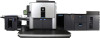
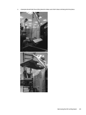
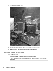
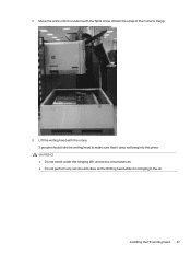
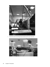
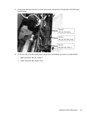
B&R Drive Replacement -- CA493-00640 Rev 00
Page 1
Modification available-reliability HP Indigo 10000 Digital Press CA493-00640 00 N/A 29 July 2013 N/A HP Confidential The information contained in this document. B&R Drive Replacement Document details Purpose Objective Scope Document number Revision number Kit number Date Related ECO Security level To describe how to replace a B&R drive. Check CE Suitcase for the most recent version of this document is accurate at the date of release. i
B&R Drive Replacement -- CA493-00640 Rev 00
Page 4
2 Procedures Procedures for the replacement of B&R drive. 1. Shut down the press software. Disconnect all cables from the B&R drive. 3. Replacing the B&R drive Follow these steps for replacing B&R drive. Figure 2-1 Removing screw 2 Chapter 2 Procedures Remove the screw. Turn off the press. 2.
B&R Drive Replacement -- CA493-00640 Rev 00
Page 6
... new drive (or the main motor itself ), do the following: 1. Safety procedure for the firmware to 1. 5. Turn the selection switch to finish updating automatically. 12. Press the ENTER button for the main motor (or you replaced the main motor itself ) is lit up in green. (This means the the SLC in... 2-4 SLC status LEDs 3. Make sure that the R/E LED is installed, do the next procedure. The SLC reboots and registers the new drive. 6. 9. Turn on the press. Access the power distribution unit (PDU). 2. If the B&R drive is for 2 seconds. Turn on the...
B&R Drive Replacement -- CA493-00640 Rev 00
Page 7
... notice This chapter contains a table of revisions, printing instructions, and a notice of this document. Revision CA493-00640 Rev 00 Description Initial document Responsible Engineer (TS) Press Group Manager Engineering Documentation Manager Configuration Control Written by Uzi Itzhak Guy Bahar Amit Levi Ronit Shugal / Idit Sharon-Muchtar Sigal Aknin Yehudah Goldberg Confidentiality...
HD Writing Head Service Document
Page 1
Information only HP Indigo 10000 Digital Press HP Indigo 12000 Digital Press (with HD writing head installed) Document number Revision number Kit number Date Related ECO Security level HP Indigo 15K Digital Press (with HD writing head installed) CA493-04420 Rev04 None 22 October 2023 None HP Confidential The information contained in this document. HD Writing Head Service Document Document details Purpose...
HD Writing Head Service Document
Page 2
...)...60 Appendix A Appendix A - HD writing head spare parts ...77 Replacing the spare parts...80 Replacing the PIP underlayer for HD presses ...94 Replacing the writing head vacuum system ...96 Appendix E Revision history and confidentiality notice...102 Revision History ...102 Printing instructions...102 Confidentiality... notice...103 ii Installing the motorized interface shipment dampers 64 Removing the press top covers...64 Installing the front and rear side dampers...67 Installing the feeder side damper...70 Appendix C Appendix C -
HD Writing Head Service Document
Page 4
Turn off the press software. Replacing the HD writing head Removal and replacemennt of the press platform. 3. Turn off the press. 2. Remove the front part of the HD writing head. Place ladders at the front side and the rear side of the HD writing head. 1. Removing the HD writing head Removal of the press engine. 2 Chapter 2 Procedures 2 Procedures Procedures for how to install, calibrate, and troubleshoot the HD writing head.
HD Writing Head Service Document
Page 6
6. Slide the remaining 2 panels over the writing head and remove them from the press. 4 Chapter 2 Procedures Remove the tray with the fan. 7.
HD Writing Head Service Document
Page 7
Removing the HD writing head 5 Remove the center support from the roof of the press. There are 4 screws on each end. 8.
HD Writing Head Service Document
Page 8
Remove the 2 screws on entrance side and the exit side and all of the screws along the front edge of the roof frame from the press. Remove the front part of the engine. 6 Chapter 2 Procedures 9.
HD Writing Head Service Document
Page 11
Disconnect the temperature sensor bracket from cables W12058 and W12568. 15. Removing the HD writing head 9 Attach the cables to the wall with a tie wrap. 14. Disconnect the 3 electrical connectors from the writing head as shown below. Access the WH mount panel at the front side of the press.
HD Writing Head Service Document
Page 12
Access the WH heater panel at the press top exit side (above the PARS shuttle area). 10 Chapter 2 Procedures 16.
HD Writing Head Service Document
Page 17
Lift the crane on top off the press and Insert the crane assembly into the crane adapter slot. WARNING! The motorized Spitz crane is heavy. 2 people should install the crane. 23. Removing the HD writing head 15
HD Writing Head Service Document
Page 21
Make sure that the Crane strap orientation is over the top of 4 min. Do not attempt to the press with the strap running from the end of the arm over the top of cool-down time. 29. b. Removing the HD writing head 19 WARNING! ...
HD Writing Head Service Document
Page 23
Make sure the box is at the correct position. Removing the HD writing head 21 Connect the lifting jig to the writing head and attach the crane hook to the press. Cover the press front door with a protective cover (you may use the HD box top cover sponge) c. 31. Prepare for moving the WH: a. Place the ladder next to the Jig center. Make sure the all the 5 knobs are closed tightly. 32. b.
HD Writing Head Service Document
Page 25
Removing the HD writing head 23 b. 2 people should hold the writing head to make sure that it does not bang into the press.
HD Writing Head Service Document
Page 26
34. When the WH is fully seated in the picture below . Installing the HD writing head Install the HD writing head. 1. Place the WH box next to place the box and lift the WH from the press and make room for the new HD box. Move the box away from a different orientation than shown in the box, remove the lifting jig and close the box. 36. Do not attempt to the press with the orientation shown below . 24 Chapter 2 Procedures Lower the writing head into the box. 35.
HD Writing Head Service Document
Page 29
WARNING! ● Do not stand under the hanging WH unit at any circumstances. ● Do not perform any service activities on the Writing head while it is underneath the Spitz crane. 5. Attach the strap of the crane to make sure that it is hanging in the air. Move the crate until it does not bang into the press. Lift the writing head with the crane. 2 people should hold the writing head to the jig. 6. Installing the HD writing head 27
HD Writing Head Service Document
Page 30
7. Rotate the crane and writing head clock-wise until it is over the press. 28 Chapter 2 Procedures
HD Writing Head Service Document
Page 37
At the press exit side of the WH, connect the 3 sensor connectors to the top side of cable W12124. ● Upper connector: WH_Air_Heater_P ● Lower connector: WH_Heater_Out_P Installing the HD writing head 35 21. At the rear side of the WH heater panel, connect the 2 white Molex connectors of the WH heater panel bracket. 22.