
Service Guide
Page 3
... the skin or a soft surface, such as pillows or rugs or clothing, to block airflow. Safety warning notice Å WARNING: To reduce the possibility of heat-related injuries or of Information Technology Equipment (IEC 60950). Also, do not place the computer directly on a hard, flat surface. Use the computer only on...
... the skin or a soft surface, such as pillows or rugs or clothing, to block airflow. Safety warning notice Å WARNING: To reduce the possibility of heat-related injuries or of Information Technology Equipment (IEC 60950). Also, do not place the computer directly on a hard, flat surface. Use the computer only on...
Service Guide
Page 5
... 4-30 TouchPad on/off button board and board bracket 4-32 Audio board 4-34 Bluetooth module 4-35 Speakers 4-36 USB board 4-37 System board 4-38 Fan/heat sink assembly 4-41 Processor 4-44 Power connector cable 4-46 5 Setup Utility Starting the Setup Utility 5-1 Changing the language of the Setup Utility 5-1 Navigating and selecting...
... 4-30 TouchPad on/off button board and board bracket 4-32 Audio board 4-34 Bluetooth module 4-35 Speakers 4-36 USB board 4-37 System board 4-38 Fan/heat sink assembly 4-41 Processor 4-44 Power connector cable 4-46 5 Setup Utility Starting the Setup Utility 5-1 Changing the language of the Setup Utility 5-1 Navigating and selecting...

Service Guide
Page 25
...-001 (5) Top cover (includes TouchPad board) 506849-001 (6) TouchPad on/off button board (includes cables) 496832-001 (7) Fan/heat sink assembly for use with UMA systems (includes replacement thermal material) 489126-001 Fan/heat sink assembly for use with Discrete systems (includes replacement thermal material) 489154-001 (8) TouchPad board bracket 489119-001...
...-001 (5) Top cover (includes TouchPad board) 506849-001 (6) TouchPad on/off button board (includes cables) 496832-001 (7) Fan/heat sink assembly for use with UMA systems (includes replacement thermal material) 489126-001 Fan/heat sink assembly for use with Discrete systems (includes replacement thermal material) 489154-001 (8) TouchPad board bracket 489119-001...
Service Guide
Page 36
...Slot, HDMI port, and replacement thermal material) Webcam TouchPad board bracket Fan/heat sink for use with UMA systems (includes replacement thermal material) Audio board (includes audio board cable) Fan/heat sink for use with discrete systems (includes replacement thermal material) (Continued) Intel... Core2 Duo P8400 2.26-GHz processor (3-MB L2 cache, 1066-MHz FSB) Illustrated parts catalog 3-15 Kitts ...
...Slot, HDMI port, and replacement thermal material) Webcam TouchPad board bracket Fan/heat sink for use with UMA systems (includes replacement thermal material) Audio board (includes audio board cable) Fan/heat sink for use with discrete systems (includes replacement thermal material) (Continued) Intel... Core2 Duo P8400 2.26-GHz processor (3-MB L2 cache, 1066-MHz FSB) Illustrated parts catalog 3-15 Kitts ...
Service Guide
Page 80
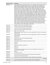
..." on page 4-12) ■ Memory module (see "Memory module" on page 4-13) ■ WLAN module (see "WLAN module" on page 4-15) ■ Fan/heat sink assembly (see "Fan/heat sink assembly" on page 4-41) ■ Processor (see "Processor" on the optical extension board. 5. Remove the four Phillips PM2.5x6.0 screws 1 that secure...
..." on page 4-12) ■ Memory module (see "Memory module" on page 4-13) ■ WLAN module (see "WLAN module" on page 4-15) ■ Fan/heat sink assembly (see "Fan/heat sink assembly" on page 4-41) ■ Processor (see "Processor" on the optical extension board. 5. Remove the four Phillips PM2.5x6.0 screws 1 that secure...
Service Guide
Page 82
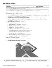
...001 489154-001 Before removing the fan, follow these steps: 1. Power button board (see "System board" on page 4-38) Remove the fan/heat sink assembly: 1. Display assembly (see "Optical drive" on page 4-8) b. Shut down through the operating system. 2. Optical drive (see "Display ...5. Remove the battery (see "Keyboard cover" on page 4-20) e. Disconnect all external devices connected to the computer. 3. Fan/heat sink assembly Description Fan/heat sink assembly (includes replacement thermal material) for use only with computer models with UMA graphics subsystem memory Fan...
...001 489154-001 Before removing the fan, follow these steps: 1. Power button board (see "System board" on page 4-38) Remove the fan/heat sink assembly: 1. Display assembly (see "Optical drive" on page 4-8) b. Shut down through the operating system. 2. Optical drive (see "Display ...5. Remove the battery (see "Keyboard cover" on page 4-20) e. Disconnect all external devices connected to the computer. 3. Fan/heat sink assembly Description Fan/heat sink assembly (includes replacement thermal material) for use only with computer models with UMA graphics subsystem memory Fan...
Service Guide
Page 83
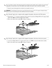
...the assembly. 3. Loosen the 4 Phillips PM2.0x11.0 spring-loaded captive screws 1 that secure the fan/heat sink assembly. 5. Removal and replacement procedures 4-42 Remove the fan/heat sink assembly 2 by lifting it straight up . ✎ Due to the adhesive quality of the thermal... assembly and system board components, you . Å WARNING: To avoid damage to the processor, loosen the fan/heat sink screws in the same sequence when installing the fan/heat sink assembly. ✎ Steps 4 through 7 apply only to computer models equipped with graphics subsystems with discrete memory. 6. ...
...the assembly. 3. Loosen the 4 Phillips PM2.0x11.0 spring-loaded captive screws 1 that secure the fan/heat sink assembly. 5. Removal and replacement procedures 4-42 Remove the fan/heat sink assembly 2 by lifting it straight up . ✎ Due to the adhesive quality of the thermal... assembly and system board components, you . Å WARNING: To avoid damage to the processor, loosen the fan/heat sink screws in the same sequence when installing the fan/heat sink assembly. ✎ Steps 4 through 7 apply only to computer models equipped with graphics subsystems with discrete memory. 6. ...
Service Guide
Page 84
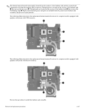
...must be thoroughly cleaned from the surfaces of the fan/heat sink 3 that services the processor 2. Thermal grease is located on the section of the fan/heat sink and the system board components each time the fan/heat sink is removed. The following illustration shows the replacement ...locations for computer models equipped with graphics subsystems with all system board, fan/heat sink assembly, and processor spare part kits. Replacement thermal grease and pads are located on the section of the fan/heat sink 1 that services the Northbridge chip 4. The following illustration shows the ...
...must be thoroughly cleaned from the surfaces of the fan/heat sink 3 that services the processor 2. Thermal grease is located on the section of the fan/heat sink and the system board components each time the fan/heat sink is removed. The following illustration shows the replacement ...locations for computer models equipped with graphics subsystems with all system board, fan/heat sink assembly, and processor spare part kits. Replacement thermal grease and pads are located on the section of the fan/heat sink 1 that services the Northbridge chip 4. The following illustration shows the ...
Service Guide
Page 86
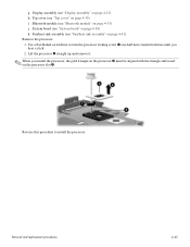
... cover" on the processor slot 4. Lift the processor 2 straight up and remove it. ✎ When you hear a click. 2. Display assembly (see "Fan/heat sink assembly" on page 4-23) h. Fan/heat sink assembly (see "Display assembly" on page 4-41) Remove the processor: 1. Removal and replacement procedures 4-45 g. Bluetooth module (see "System board" on...
... cover" on the processor slot 4. Lift the processor 2 straight up and remove it. ✎ When you hear a click. 2. Display assembly (see "Fan/heat sink assembly" on page 4-23) h. Fan/heat sink assembly (see "Display assembly" on page 4-41) Remove the processor: 1. Removal and replacement procedures 4-45 g. Bluetooth module (see "System board" on...
Service Guide
Page 114
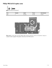
Phillips PM2.0x10.0 captive screw Color Silver Quantity 4 Length 10.0 mm Thread 2.0 mm Head diameter 5.0 mm Where used: 4 screws that secure the fan/heat sink to the base enclosure (screws are secured by C-clips) on computer models equipped with graphics subsystems with UMA memory Screw listing 7-15
Phillips PM2.0x10.0 captive screw Color Silver Quantity 4 Length 10.0 mm Thread 2.0 mm Head diameter 5.0 mm Where used: 4 screws that secure the fan/heat sink to the base enclosure (screws are secured by C-clips) on computer models equipped with graphics subsystems with UMA memory Screw listing 7-15
Service Guide
Page 115
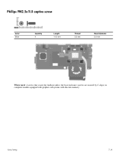
Phillips PM2.5x11.0 captive screw Color Silver Quantity 4 Length 11.0 mm Thread 2.5 mm Head diameter 5.0 mm Where used: 4 screws that secure the fan/heat sink to the base enclosure (screws are secured by C-clips) on computer models equipped with graphics subsystems with discrete memory Screw listing 7-16
Phillips PM2.5x11.0 captive screw Color Silver Quantity 4 Length 11.0 mm Thread 2.5 mm Head diameter 5.0 mm Where used: 4 screws that secure the fan/heat sink to the base enclosure (screws are secured by C-clips) on computer models equipped with graphics subsystems with discrete memory Screw listing 7-16
Service Guide
Page 135
..., removal 4-11 hard drive cover illustration 3-4, 3-11 removal 4-10 spare part number 3-11 HDMI port location 2-7 pin assignments 9-3 product description 1-5 headphone jack location 2-6 pin assignments 9-1 heat sink removal 4-41 spare part number 3-4, 3-15, 4-41 hinges removal 4-25 spare part number 3-9 I I/O address specifications 6-6 internal display switch 2-1 interrupt specifications 6-5 J jacks audio-in 2-6 audio...
..., removal 4-11 hard drive cover illustration 3-4, 3-11 removal 4-10 spare part number 3-11 HDMI port location 2-7 pin assignments 9-3 product description 1-5 headphone jack location 2-6 pin assignments 9-1 heat sink removal 4-41 spare part number 3-4, 3-15, 4-41 hinges removal 4-25 spare part number 3-9 I I/O address specifications 6-6 internal display switch 2-1 interrupt specifications 6-5 J jacks audio-in 2-6 audio...


