Drives - Windows Vista
Page 15
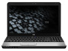
Pull the black plastic tab on the computer (1). 5. Close the cover (2). 11 Gently lower the hard drive into place (2). 3. Lift the hard drive away from the system board connector (2). 11. To install a hard drive: 1. Align the tabs on the hard drive cover with the notches on top of the hard drive to the computer (3). 4. 10. Slide the hard drive to the left until it snaps into the compartment (1). 2. Replace the 3 screws that secure the hard drive to disconnect the drive from the computer (3).
Pull the black plastic tab on the computer (1). 5. Close the cover (2). 11 Gently lower the hard drive into place (2). 3. Lift the hard drive away from the system board connector (2). 11. To install a hard drive: 1. Align the tabs on the hard drive cover with the notches on top of the hard drive to the computer (3). 4. 10. Slide the hard drive to the left until it snaps into the compartment (1). 2. Replace the 3 screws that secure the hard drive to disconnect the drive from the computer (3).
HP Notebook Hard Drives & Solid State Drives Identifying, Preventing, Diagnosing and Recovering from Drive Failures Care and Mai
Page 2
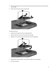
...traced to connector issues, shock events, software issues, and more . The following sections summarize some of an issue with an SSD, the HP Diagnostics should be displayed such as a clicking noise, the failure to shock events. Connector issues It is running. Symptoms may need adjustment... by software issues. Identifying, Preventing, Diagnosing, and Recovering from the hard drive to the system board. These measures include enhanced hard drive diagnostics, Intel Storage Matrix Technology, HP 3D drive guard, firmware updates, and more . Note: The following sections explain how to Solid...
...traced to connector issues, shock events, software issues, and more . The following sections summarize some of an issue with an SSD, the HP Diagnostics should be displayed such as a clicking noise, the failure to shock events. Connector issues It is running. Symptoms may need adjustment... by software issues. Identifying, Preventing, Diagnosing, and Recovering from the hard drive to the system board. These measures include enhanced hard drive diagnostics, Intel Storage Matrix Technology, HP 3D drive guard, firmware updates, and more . Note: The following sections explain how to Solid...
Service Guide
Page 5
... Display assembly 4-23 Top cover 4-30 TouchPad on/off button board and board bracket 4-32 Audio board 4-34 Bluetooth module 4-35 Speakers 4-36 USB board 4-37 System board 4-38 Fan/heat sink assembly 4-41 Processor 4-44 Power connector cable 4-46 5 Setup Utility Starting the Setup Utility 5-1 Changing the language of the Setup Utility 5-1 ...
... Display assembly 4-23 Top cover 4-30 TouchPad on/off button board and board bracket 4-32 Audio board 4-34 Bluetooth module 4-35 Speakers 4-36 USB board 4-37 System board 4-38 Fan/heat sink assembly 4-41 Processor 4-44 Power connector cable 4-46 5 Setup Utility Starting the Setup Utility 5-1 Changing the language of the Setup Utility 5-1 ...

Service Guide
Page 25
...the United States (silver) 502958-001 (3) Keyboard cover 506848-001 (4) Power button board (includes power button board cable) 496830-001 (5) Top cover (includes TouchPad board) 506849-001 (6) TouchPad on/off button board (includes cables) 496832-001 (7) Fan/heat sink assembly for use with UMA systems... thermal material) 489126-001 Fan/heat sink assembly for use with Discrete systems (includes replacement thermal material) 489154-001 (8) TouchPad board bracket 489119-001 Plastics Kit (see Plastics Kit on page 3-9 for Presario CQ60 computer models only; includes built-in modem and...
...the United States (silver) 502958-001 (3) Keyboard cover 506848-001 (4) Power button board (includes power button board cable) 496830-001 (5) Top cover (includes TouchPad board) 506849-001 (6) TouchPad on/off button board (includes cables) 496832-001 (7) Fan/heat sink assembly for use with UMA systems... thermal material) 489126-001 Fan/heat sink assembly for use with Discrete systems (includes replacement thermal material) 489154-001 (8) TouchPad board bracket 489119-001 Plastics Kit (see Plastics Kit on page 3-9 for Presario CQ60 computer models only; includes built-in modem and...
Service Guide
Page 26
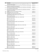
...port, and replacement thermal material) UMA system board, NVIDIA (for Presario CQ60 use only; Item (12) (13) (14) Description UMA system board, NVIDIA (includes built-in modem, Digital Media Slot, and replacement thermal material) UMA system board, NVIDIA (for Presario CQ60 use only; includes... built-in modem and replacement thermal material) Speakers (include left and right speakers and cables) Audio board (includes audio board cable) Processor (includes replacement thermal material) Intel Core2 Duo processor (6-MB L2 cache, 1066-MHz FSB): ■ T9400 ...
...port, and replacement thermal material) UMA system board, NVIDIA (for Presario CQ60 use only; Item (12) (13) (14) Description UMA system board, NVIDIA (includes built-in modem, Digital Media Slot, and replacement thermal material) UMA system board, NVIDIA (for Presario CQ60 use only; includes... built-in modem and replacement thermal material) Speakers (include left and right speakers and cables) Audio board (includes audio board cable) Processor (includes replacement thermal material) Intel Core2 Duo processor (6-MB L2 cache, 1066-MHz FSB): ■ T9400 ...
Service Guide
Page 27
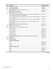
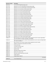
Item (15) (16) (17) (18) (19) (20) (21) (22) Description Power connector cable Optical extension board Bluetooth® module (does not include Bluetooth cable) Bluetooth cable (not illustrated) Base enclosure (includes rubber feet) For use only with computer models equipped with a ...
Item (15) (16) (17) (18) (19) (20) (21) (22) Description Power connector cable Optical extension board Bluetooth® module (does not include Bluetooth cable) Bluetooth cable (not illustrated) Base enclosure (includes rubber feet) For use only with computer models equipped with a ...
Service Guide
Page 36
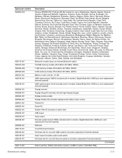
...Digital Media Slot, HDMI port, and replacement thermal material) Webcam TouchPad board bracket Fan/heat sink for use with UMA systems (includes replacement thermal material) Audio board (includes audio board cable) Fan/heat sink for use with discrete systems (includes replacement thermal...Display Rubber Kit (includes display bezel rubber screw covers) Plastics Kit Screw Kit Rubber Feet Kit (includes 6 rubber feet) USB board Audio board Discrete system board, PM45 (includes built-in Afghanistan, Albania, Algeria, Andorra, Angola, Antigua and Barbuda, Argentina, Armenia, Aruba, Australia, Austria...
...Digital Media Slot, HDMI port, and replacement thermal material) Webcam TouchPad board bracket Fan/heat sink for use with UMA systems (includes replacement thermal material) Audio board (includes audio board cable) Fan/heat sink for use with discrete systems (includes replacement thermal...Display Rubber Kit (includes display bezel rubber screw covers) Plastics Kit Screw Kit Rubber Feet Kit (includes 6 rubber feet) USB board Audio board Discrete system board, PM45 (includes built-in Afghanistan, Albania, Algeria, Andorra, Angola, Antigua and Barbuda, Argentina, Armenia, Aruba, Australia, Austria...
Service Guide
Page 37
... modem, Digital Media Slot, and replacement thermal material) Discrete system board, PM45 (includes built-in modem, Digital Media Slot, and replacement thermal material) 16-inch WXGA BrightView display assembly for HP G60 computer models (includes microphone) 16-inch WXGA BrightView display assembly for HP G60 computer models (includes webcam module and cable, microphone and cable...
... modem, Digital Media Slot, and replacement thermal material) Discrete system board, PM45 (includes built-in modem, Digital Media Slot, and replacement thermal material) 16-inch WXGA BrightView display assembly for HP G60 computer models (includes microphone) 16-inch WXGA BrightView display assembly for HP G60 computer models (includes webcam module and cable, microphone and cable...
Service Guide
Page 38
... Base enclosure for use only with computer models equipped with a built-in modem Speakers (include left and right speakers and cables) Power button board TouchPad on/off button board Power connector cable Bluetooth cable USB cable (includes num lock cable) Modem with connector cable Microphone cable (includes caps lock cable) Display Cable...
... Base enclosure for use only with computer models equipped with a built-in modem Speakers (include left and right speakers and cables) Power button board TouchPad on/off button board Power connector cable Bluetooth cable USB cable (includes num lock cable) Modem with connector cable Microphone cable (includes caps lock cable) Display Cable...
Service Guide
Page 39
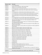
... DVD±RW and CD-RW SuperMulti Double-Layer Combo Drive with HP G60 computer models (includes microphone and webcam) UMA system board, NVIDIA (includes built-in modem, HDMI port, and replacement thermal material) UMA system board, NVIDIA (for Presario CQ60 use only; Spare part number 496844-001...(includes microphone and webcam) 15.6-inch display bezel for use with HP G60 computer models (includes microphone) 15.6-inch display bezel for use with LightScribe Blu-ray ROM DVD±RW SuperMulti DL Drive UMA system board, GL40 (for Presario CQ60 computer models only; includes built-in ...
... DVD±RW and CD-RW SuperMulti Double-Layer Combo Drive with HP G60 computer models (includes microphone and webcam) UMA system board, NVIDIA (includes built-in modem, HDMI port, and replacement thermal material) UMA system board, NVIDIA (for Presario CQ60 use only; Spare part number 496844-001...(includes microphone and webcam) 15.6-inch display bezel for use with HP G60 computer models (includes microphone) 15.6-inch display bezel for use with LightScribe Blu-ray ROM DVD±RW SuperMulti DL Drive UMA system board, GL40 (for Presario CQ60 computer models only; includes built-in ...
Service Guide
Page 40
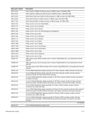
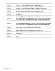
... antenna transceivers and cables, microphone and cable, and logo) 15.6-inch WXGA BrightView silver display assembly for HP G60 computer models (includes microphone and cable, and logo) 15.6-inch WXGA BrightView silver display assembly for HP G60 computer models (includes webcam module and cable, 2 WLAN antenna transceivers and cables, microphone and cable, and logo... bracket, connector, and screws) Base enclosure (includes built-in-modem, HDMI port, without a card reader) 200-GB hard drive Keyboard cover Top cover Optical extension board Illustrated parts catalog 3-19
... antenna transceivers and cables, microphone and cable, and logo) 15.6-inch WXGA BrightView silver display assembly for HP G60 computer models (includes microphone and cable, and logo) 15.6-inch WXGA BrightView silver display assembly for HP G60 computer models (includes webcam module and cable, 2 WLAN antenna transceivers and cables, microphone and cable, and logo... bracket, connector, and screws) Base enclosure (includes built-in-modem, HDMI port, without a card reader) 200-GB hard drive Keyboard cover Top cover Optical extension board Illustrated parts catalog 3-19
Service Guide
Page 52
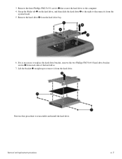
... slide the hard drive 3 to the right to remove it from the hard drive. Lift the bracket 2 straight up to disconnect it from the system board. 5. Removal and replacement procedures 4-11 Remove the three Phillips PM2.5×5.0 screws 1 that secure the hard drive to reassemble and install the hard drive. Reverse...
... slide the hard drive 3 to the right to remove it from the hard drive. Lift the bracket 2 straight up to disconnect it from the system board. 5. Removal and replacement procedures 4-11 Remove the three Phillips PM2.5×5.0 screws 1 that secure the hard drive to reassemble and install the hard drive. Reverse...
Service Guide
Page 53
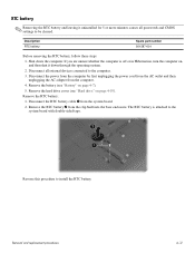
... clip built into the base enclosure. Disconnect all passwords and CMOS settings to be cleared. Remove the RTC battery 2 from the system board. 2. Reverse this procedure to the system board with double-sided tape. Removal and replacement procedures 4-12 Shut down through the operating system. 2. If you are unsure whether the computer...
... clip built into the base enclosure. Disconnect all passwords and CMOS settings to be cleared. Remove the RTC battery 2 from the system board. 2. Reverse this procedure to the system board with double-sided tape. Removal and replacement procedures 4-12 Shut down through the operating system. 2. If you are unsure whether the computer...
Service Guide
Page 60
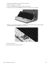
Removal and replacement procedures 4-19 Open the computer as far as possible. 5. Remove the keyboard. Release the tabs 1 along the right and left edges of the keyboard 2, and then slide it back until it rests on the display. 7. Reverse this procedure to which the keyboard cable is attached, and then disconnect the keyboard cable 2 from the system board. 8. Lift the rear edge of the keyboard. 6. Turn the computer display-side up, with the front toward you. 4. 3. Release the zero insertion force (ZIF) connector 1 to install the keyboard.
Removal and replacement procedures 4-19 Open the computer as far as possible. 5. Remove the keyboard. Release the tabs 1 along the right and left edges of the keyboard 2, and then slide it back until it rests on the display. 7. Reverse this procedure to which the keyboard cable is attached, and then disconnect the keyboard cable 2 from the system board. 8. Lift the rear edge of the keyboard. 6. Turn the computer display-side up, with the front toward you. 4. 3. Release the zero insertion force (ZIF) connector 1 to install the keyboard.
Service Guide
Page 62
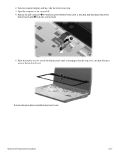
2. Slide the keyboard cover toward the display panel until it disengages from the system board. 5. Open the computer as far as possible. 4. Reverse this procedure to which the power button board cable is attached, and disconnect the power button board cable 2 from the top cover, and then lift up , with the front toward you. 3. Turn the computer display-side up to remove the keyboard cover. Removal and replacement procedures 4-21 Release the ZIF connector 1 to install the keyboard cover.
2. Slide the keyboard cover toward the display panel until it disengages from the system board. 5. Open the computer as far as possible. 4. Reverse this procedure to which the power button board cable is attached, and disconnect the power button board cable 2 from the top cover, and then lift up , with the front toward you. 3. Turn the computer display-side up to remove the keyboard cover. Removal and replacement procedures 4-21 Release the ZIF connector 1 to install the keyboard cover.
Service Guide
Page 63
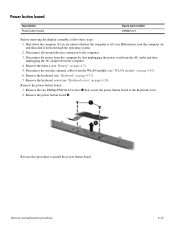
... the keyboard (see "Battery" on page 4-7). 5. Remove the power button board: 1. Remove the two Phillips PM2.0x4.0 screws 1 that secure the power button board to install the power button board. Reverse this procedure to the keyboard cover. 2. Power button board Description Power button board Spare part number 496830-001 Before removing the display assembly, follow...
... the keyboard (see "Battery" on page 4-7). 5. Remove the power button board: 1. Remove the two Phillips PM2.0x4.0 screws 1 that secure the power button board to install the power button board. Reverse this procedure to the keyboard cover. 2. Power button board Description Power button board Spare part number 496830-001 Before removing the display assembly, follow...
Service Guide
Page 65
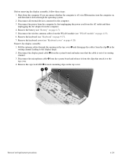
...display assembly: 1. Removal and replacement procedures 4-24 Shut down through the opening in the top cover 1 and disengage the cables from the system board and make sure that attach it down the computer. Remove the caps lock LED 5 from the clips that the cable is off or in... the routing channel leading to the display hinge. 2. Disconnect the microphone cable 4 from the system board and release it from its routing channel. 3. Before removing the display assembly, follow these steps: 1. Disconnect the power from the computer by first...
...display assembly: 1. Removal and replacement procedures 4-24 Shut down through the opening in the top cover 1 and disengage the cables from the system board and make sure that attach it down the computer. Remove the caps lock LED 5 from the clips that the cable is off or in... the routing channel leading to the display hinge. 2. Disconnect the microphone cable 4 from the system board and release it from its routing channel. 3. Before removing the display assembly, follow these steps: 1. Disconnect the power from the computer by first...

Service Guide
Page 71
... unsure whether the computer is off or in Hibernation, turn the computer on page 4-22) f. Shut down through the operating system. 2. If you . 2. Power button board (see "Power button board" on , and then shut it down the computer.
... unsure whether the computer is off or in Hibernation, turn the computer on page 4-22) f. Shut down through the operating system. 2. If you . 2. Power button board (see "Power button board" on , and then shut it down the computer.

Service Guide
Page 72
Remove the following screws: a. Four Phillips PM2.0x6.0 screws 1 b. Turn the computer right-side up, with the front facing you. 5. Lift the rear edge of the top cover 1 until the top cover disengages from the system board. 6. Remove the top cover 2. One Phillips PM2.0x4.0 screw 2 7. Reverse this procedure to which the TouchPad cable is attached, and disconnect the TouchPad cable from the base enclosure. 8. Release the ZIF connector to install the top cover. 4. Removal and replacement procedures 4-31
Remove the following screws: a. Four Phillips PM2.0x6.0 screws 1 b. Turn the computer right-side up, with the front facing you. 5. Lift the rear edge of the top cover 1 until the top cover disengages from the system board. 6. Remove the top cover 2. One Phillips PM2.0x4.0 screw 2 7. Reverse this procedure to which the TouchPad cable is attached, and disconnect the TouchPad cable from the base enclosure. 8. Release the ZIF connector to install the top cover. 4. Removal and replacement procedures 4-31
Service Guide
Page 73
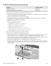
...the computer. 4. Remove the following components: a. Removal and replacement procedures 4-32 TouchPad on/off button board and board bracket Description TouchPad board bracket TouchPad on/off button board (includes cables) Spare Parts Number 489119-001 496832-001 Before removing the TouchPad on/off or in ... "Keyboard cover" on page 4-8) b. Keyboard cover (see "Optical drive" on page 4-20) e. Power button board (see "Hard drive" on page 4-22) f. Hard drive (see "Power button board" on page 4-10) c. Turn the top cover upside down the computer. If you . 2. Release the ZIF...
...the computer. 4. Remove the following components: a. Removal and replacement procedures 4-32 TouchPad on/off button board and board bracket Description TouchPad board bracket TouchPad on/off button board (includes cables) Spare Parts Number 489119-001 496832-001 Before removing the TouchPad on/off or in ... "Keyboard cover" on page 4-8) b. Keyboard cover (see "Optical drive" on page 4-20) e. Power button board (see "Hard drive" on page 4-22) f. Hard drive (see "Power button board" on page 4-10) c. Turn the top cover upside down the computer. If you . 2. Release the ZIF...


