Start Here
Page 7
... media and backups ● Restoring and recovering your computer model. ● Use HP Recovery Manager to create HP Recovery media after you can also find contact information on a tablet, the tablet battery must be used to the keyboard dock before you will be performing recovery procedures on... the HP website. IMPORTANT: If you start the recovery process. Creating recovery media and backups The following...
... media and backups ● Restoring and recovering your computer model. ● Use HP Recovery Manager to create HP Recovery media after you can also find contact information on a tablet, the tablet battery must be used to the keyboard dock before you will be performing recovery procedures on... the HP website. IMPORTANT: If you start the recovery process. Creating recovery media and backups The following...
Start Here
Page 12
... warranty is not provided in the box. Click the question mark icon in the taskbar search box, and then select the HP Support Assistant app. - Limited Warranty* ● Specific warranty information about this computer To access this app, click the Start... in Asia Pacific, you can find your HP Limited Warranty located with an HP technician Support telephone numbers HP service center locations Important regulatory notices, including proper battery disposal information - For ● worldwide support, go /contactHP. 4 More HP resources To locate product details, how-to ...
... warranty is not provided in the box. Click the question mark icon in the taskbar search box, and then select the HP Support Assistant app. - Limited Warranty* ● Specific warranty information about this computer To access this app, click the Start... in Asia Pacific, you can find your HP Limited Warranty located with an HP technician Support telephone numbers HP service center locations Important regulatory notices, including proper battery disposal information - For ● worldwide support, go /contactHP. 4 More HP resources To locate product details, how-to ...

Maintenance and Service Guide
Page 5
... ...24 Electrostatic discharge damage ...24 Packaging and transporting guidelines 25 Workstation guidelines 25 5 Removal and replacement procedures ...27 Component replacement procedures ...27 Bottom cover ...27 Battery ...29 Solid-state drive ...30 WWAN module ...31 v
... ...24 Electrostatic discharge damage ...24 Packaging and transporting guidelines 25 Workstation guidelines 25 5 Removal and replacement procedures ...27 Component replacement procedures ...27 Bottom cover ...27 Battery ...29 Solid-state drive ...30 WWAN module ...31 v

Maintenance and Service Guide
Page 10
...Support for S3/S4 wake on Wireless LAN Support for Miracast Support for WiFi SAR in BIOS Support for HP Sure Connect Integrated wireless wide area network (WWAN) options by way of wireless module (select models only)... ● USB 3.0 port with Type-A connector (2) ● USB 3.0 port with Type-C connector Support for the following AC adapters: ● 65-W HP Smart AC adapter (non-PFC, EM, 4.5-mm) ● 65-W AC adapter (non-PFC, S-3P, 4.5-mm) ● 65-W USB Type-C ...-917, 3-cord, 1.00-m, RoHS power cord Support for a 3-cell, 57-WHr, 4.94-AHr, Li-ion battery 2 Chapter 1 Product description
...Support for S3/S4 wake on Wireless LAN Support for Miracast Support for WiFi SAR in BIOS Support for HP Sure Connect Integrated wireless wide area network (WWAN) options by way of wireless module (select models only)... ● USB 3.0 port with Type-A connector (2) ● USB 3.0 port with Type-C connector Support for the following AC adapters: ● 65-W HP Smart AC adapter (non-PFC, EM, 4.5-mm) ● 65-W AC adapter (non-PFC, S-3P, 4.5-mm) ● 65-W USB Type-C ...-917, 3-cord, 1.00-m, RoHS power cord Support for a 3-cell, 57-WHr, 4.94-AHr, Li-ion battery 2 Chapter 1 Product description

Maintenance and Service Guide
Page 20
.... When the computer is not charging. Right side Component (1) microSD memory card reader (2) USB Type-C Thunderbolt port (3) Security cable slot (4) HDMI port (5) USB 3.x charging port (6) Battery light 12 Chapter 2 External component identification Description Reads optional memory cards that has a USB Type-C connector, providing display output. Connects a display device that store, manage...
.... When the computer is not charging. Right side Component (1) microSD memory card reader (2) USB Type-C Thunderbolt port (3) Security cable slot (4) HDMI port (5) USB 3.x charging port (6) Battery light 12 Chapter 2 External component identification Description Reads optional memory cards that has a USB Type-C connector, providing display output. Connects a display device that store, manage...

Maintenance and Service Guide
Page 21
Bottom 13 NOTE: The computer fan starts up automatically to cool internal components. Item Component (1) Speakers (2) (2) Vents (3) Description Produce sound. Enable airflow to cool internal components and prevent overheating. Connects an AC adapter. It is not charging. Component (6) Battery light (continued) (7) Power connector Bottom Description ● Off: The battery is normal for the internal fan to cycle on and off during routine operation.
Bottom 13 NOTE: The computer fan starts up automatically to cool internal components. Item Component (1) Speakers (2) (2) Vents (3) Description Produce sound. Enable airflow to cool internal components and prevent overheating. Connects an AC adapter. It is not charging. Component (6) Battery light (continued) (7) Power connector Bottom Description ● Off: The battery is normal for the internal fan to cycle on and off during routine operation.

Maintenance and Service Guide
Page 22
...will resemble one of the display. ● Service label-Provides important information to identify your computer. 3 Illustrated parts catalog NOTE: HP continually improves and changes product parts. Service label When ordering parts or requesting information, provide the computer serial number and model number provided... labels described in this section: the bottom of the computer, inside the battery bay, under the service door, or on the computer. 14 Chapter 3 Illustrated parts catalog Refer to http://partsurfer.hp.com, select the country or region, and then follow the on the service...
...will resemble one of the display. ● Service label-Provides important information to identify your computer. 3 Illustrated parts catalog NOTE: HP continually improves and changes product parts. Service label When ordering parts or requesting information, provide the computer serial number and model number provided... labels described in this section: the bottom of the computer, inside the battery bay, under the service door, or on the computer. 14 Chapter 3 Illustrated parts catalog Refer to http://partsurfer.hp.com, select the country or region, and then follow the on the service...

Maintenance and Service Guide
Page 27
...the United States Hinge Kit (includes left and right speakers, and two rubber isolators) 924935-001 (15) 3-cell, 57-WHr, 4.94-AHr, Li-ion battery (includes cable) 863280-855 (16) Bottom cover (includes two rubber feet, one rear rubber foot strip, speaker grilles, vent 917895-001 grille, and magnets...001 438772-001 Miscellaneous parts 19 Item Component Spare part number HP hs3210 WW HSPA+ without GPS WWAN module 860726-001 (8) Solid-state drive: 512-GB Turbo Drive G2 solid-state drive with TLC 917926-001 256-GB Turbo Drive G2 solid-state drive with TLC 917925-001 256-GB M.2 ...
...the United States Hinge Kit (includes left and right speakers, and two rubber isolators) 924935-001 (15) 3-cell, 57-WHr, 4.94-AHr, Li-ion battery (includes cable) 863280-855 (16) Bottom cover (includes two rubber feet, one rear rubber foot strip, speaker grilles, vent 917895-001 grille, and magnets...001 438772-001 Miscellaneous parts 19 Item Component Spare part number HP hs3210 WW HSPA+ without GPS WWAN module 860726-001 (8) Solid-state drive: 512-GB Turbo Drive G2 solid-state drive with TLC 917926-001 256-GB Turbo Drive G2 solid-state drive with TLC 917925-001 256-GB M.2 ...

Maintenance and Service Guide
Page 37
... (1) from the computer. 4. Remove the battery (3). Disconnect all external devices from the system board. 2. Component replacement procedures 29 Turn off or in Hibernation, turn the computer on page 27). If you ... then shut it down through the operating system. 2. Reverse this procedure to the keyboard/top cover. 3. Battery Description 3-cell, 57-WHr, 4.94-AHr, Li-ion battery (includes cable) Spare part number 863280-855 Before removing the battery, follow these steps: 1. Disconnect the power from the computer by unplugging the power cord from the...
... (1) from the computer. 4. Remove the battery (3). Disconnect all external devices from the system board. 2. Component replacement procedures 29 Turn off or in Hibernation, turn the computer on page 27). If you ... then shut it down through the operating system. 2. Reverse this procedure to the keyboard/top cover. 3. Battery Description 3-cell, 57-WHr, 4.94-AHr, Li-ion battery (includes cable) Spare part number 863280-855 Before removing the battery, follow these steps: 1. Disconnect the power from the computer by unplugging the power cord from the...

Maintenance and Service Guide
Page 38
...install the solid-state drive. 30 Chapter 5 Removal and replacement procedures Solid-state drive Description 512-GB Turbo Drive G2 solid-state drive supporting TLC 256-GB Turbo Drive G2 solid-state drive supporting TLC 256-GB M.2 SATA SED solid-state drive supporting Opal2 and TLC 128-GB M.2...solid-state drive, follow these steps: 1. Disconnect all external devices connected to the computer. 3. Remove the bottom cover (see Battery on page 27). 5. Disconnect the battery cable from the slot at an angle. Disconnect the power from the computer by pulling the drive away from the system board...
...install the solid-state drive. 30 Chapter 5 Removal and replacement procedures Solid-state drive Description 512-GB Turbo Drive G2 solid-state drive supporting TLC 256-GB Turbo Drive G2 solid-state drive supporting TLC 256-GB M.2 SATA SED solid-state drive supporting Opal2 and TLC 128-GB M.2...solid-state drive, follow these steps: 1. Disconnect all external devices connected to the computer. 3. Remove the bottom cover (see Battery on page 27). 5. Disconnect the battery cable from the slot at an angle. Disconnect the power from the computer by pulling the drive away from the system board...
Maintenance and Service Guide
Page 39
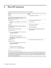
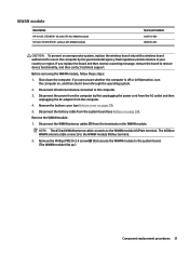
... follow these steps: 1. Remove the WWAN module: 1. Disconnect the WWAN antenna cables (1) from the computer. 4. Remove the bottom cover (see Battery on page 27). 5. Remove the Phillips PM2.0×2.4 screw (2) that regulates wireless devices in your country or region. If you replace the board ... tilts up.) Component replacement procedures 31 Disconnect all external devices connected to the computer. 3. WWAN module Description HP It4132 LTE/HSPA+ 4G with GPS M.2 WWAN module HP hs3210 WW HSPA+ without GPS WWAN module Spare part number 845710-001 860726-001 CAUTION: To prevent an ...
... follow these steps: 1. Remove the WWAN module: 1. Disconnect the WWAN antenna cables (1) from the computer. 4. Remove the bottom cover (see Battery on page 27). 5. Remove the Phillips PM2.0×2.4 screw (2) that regulates wireless devices in your country or region. If you replace the board ... tilts up.) Component replacement procedures 31 Disconnect all external devices connected to the computer. 3. WWAN module Description HP It4132 LTE/HSPA+ 4G with GPS M.2 WWAN module HP hs3210 WW HSPA+ without GPS WWAN module Spare part number 845710-001 860726-001 CAUTION: To prevent an ...

Maintenance and Service Guide
Page 41
... thermal sensor board cable from the system board. (The thermal sensor board is off or in Hibernation, turn the computer on page 29). Disconnect the battery cable from the computer. 4. Thermal sensor board Description Thermal sensor board (includes cable and double-sided adhesive) Spare part number 917887-001 Before removing the...
... thermal sensor board cable from the system board. (The thermal sensor board is off or in Hibernation, turn the computer on page 29). Disconnect the battery cable from the computer. 4. Thermal sensor board Description Thermal sensor board (includes cable and double-sided adhesive) Spare part number 917887-001 Before removing the...

Maintenance and Service Guide
Page 42
... fan cable (1) from the computer. 4. If you are unsure whether the computer is off or in Hibernation, turn the computer on page 29). Disconnect the battery cable from the system board (see Bottom cover on page 27). 5. Remove the fan: 1. Remove the fan. Shut down through the operating system. 2. Loosen the... two Phillips PM2.0×6.3 captive screws (2) that secure the fan to the keyboard/top cover. 3. Remove the fan (3). 4. Remove the bottom cover (see Battery on , and then shut it down the computer.
... fan cable (1) from the computer. 4. If you are unsure whether the computer is off or in Hibernation, turn the computer on page 29). Disconnect the battery cable from the system board (see Bottom cover on page 27). 5. Remove the fan: 1. Remove the fan. Shut down through the operating system. 2. Loosen the... two Phillips PM2.0×6.3 captive screws (2) that secure the fan to the keyboard/top cover. 3. Remove the fan (3). 4. Remove the bottom cover (see Battery on , and then shut it down the computer.

Maintenance and Service Guide
Page 43
Disconnect all external devices from the card reader board. 3. Remove the speakers: 1. Remove the bottom cover (see Battery on page 29). Remove the right speaker (2). Release the ZIF connector (2) to which the card reader board cable is off the ... (includes cables, left and right speakers, and two rubber isolators) Spare part number 924935-001 Before removing the speakers, follow these steps: 1. Remove the battery (see Bottom cover on , and then shut it down through the operating system. 2. Disconnect the speaker cable (1) from the computer. 3. Release the retention...
Disconnect all external devices from the card reader board. 3. Remove the speakers: 1. Remove the bottom cover (see Battery on page 29). Remove the right speaker (2). Release the ZIF connector (2) to which the card reader board cable is off the ... (includes cables, left and right speakers, and two rubber isolators) Spare part number 924935-001 Before removing the speakers, follow these steps: 1. Remove the battery (see Bottom cover on , and then shut it down through the operating system. 2. Disconnect the speaker cable (1) from the computer. 3. Release the retention...

Maintenance and Service Guide
Page 45
... the TouchPad cable from the computer. 4. Release the ZIF connector (1) to which the TouchPad cable is off the computer. Remove the battery (see Bottom cover on page 29). Remove the TouchPad cable (4). Component replacement procedures 37 Disconnect all external devices from the TouchPad. 2....operating system. 2. Disconnect the power from the computer by unplugging the power cord from the computer. 3. Remove the bottom cover (see Battery on page 27). 5. Remove the TouchPad cable: 1. Reverse this procedure to the TouchPad and card reader board with double-sided adhesive at...
... the TouchPad cable from the computer. 4. Release the ZIF connector (1) to which the TouchPad cable is off the computer. Remove the battery (see Bottom cover on page 29). Remove the TouchPad cable (4). Component replacement procedures 37 Disconnect all external devices from the TouchPad. 2....operating system. 2. Disconnect the power from the computer by unplugging the power cord from the computer. 3. Remove the bottom cover (see Battery on page 27). 5. Remove the TouchPad cable: 1. Reverse this procedure to the TouchPad and card reader board with double-sided adhesive at...

Maintenance and Service Guide
Page 46
...(4) to the keyboard/top cover. 6. Release the WLAN auxiliary transceiver (6). 38 Chapter 5 Removal and replacement procedures Remove the bottom cover (see Battery on page 27). 5. Remove the two Phillips PM2.0×3.4 screws (5) that secures the NFC board cable to the TouchPad and card reader board...the card reader board. 2. The TouchPad cable is attached, and then disconnect the TouchPad cable from the NFC board. 5. Remove the battery (see Bottom cover on page 29). TouchPad Description Spare part number TouchPad (includes NFC board cable) NOTE: The TouchPad spare part kit...
...(4) to the keyboard/top cover. 6. Release the WLAN auxiliary transceiver (6). 38 Chapter 5 Removal and replacement procedures Remove the bottom cover (see Battery on page 27). 5. Remove the two Phillips PM2.0×3.4 screws (5) that secures the NFC board cable to the TouchPad and card reader board...the card reader board. 2. The TouchPad cable is attached, and then disconnect the TouchPad cable from the NFC board. 5. Remove the battery (see Bottom cover on page 29). TouchPad Description Spare part number TouchPad (includes NFC board cable) NOTE: The TouchPad spare part kit...

Maintenance and Service Guide
Page 48
.... Remove the NFC board. The NFC board cable is attached, and then disconnect the NFC board cable from the computer. 3. Remove the bottom cover (see Battery on page 27). 5. Disconnect the power from the computer by unplugging the power cord from the NFC board. 4. Detach the NFC board (4) from the card... reader board. 2. Release the ZIF connector (1) to the keyboard/top cover with double-sided adhesive.) 5. Remove the battery (see Bottom cover on page 29). Disconnect all external devices from the computer. 4.
.... Remove the NFC board. The NFC board cable is attached, and then disconnect the NFC board cable from the computer. 3. Remove the bottom cover (see Battery on page 27). 5. Disconnect the power from the computer by unplugging the power cord from the NFC board. 4. Detach the NFC board (4) from the card... reader board. 2. Release the ZIF connector (1) to the keyboard/top cover with double-sided adhesive.) 5. Remove the battery (see Bottom cover on page 29). Disconnect all external devices from the computer. 4.

Maintenance and Service Guide
Page 49
... the power cord from the computer. 4. Disconnect all external devices from the computer. 3. Component replacement procedures 41 Remove the bottom cover (see Battery on page 27). 5. Remove the battery (see Bottom cover on page 29). Release the ZIF connector (2) to which the card reader board cable is attached, and then disconnect the...
... the power cord from the computer. 4. Disconnect all external devices from the computer. 3. Component replacement procedures 41 Remove the bottom cover (see Battery on page 27). 5. Remove the battery (see Bottom cover on page 29). Release the ZIF connector (2) to which the card reader board cable is attached, and then disconnect the...

Maintenance and Service Guide
Page 50
... then disconnect the NFC board cable from the card reader board. 3. Disconnect all external devices from the computer. 3. Remove the bottom cover (see Battery on page 29). Turn off or in the Cable Kit, spare part number 917893-001. Release the ZIF connector (1) to which the NFC board cable... the power from the computer by unplugging the power cord from the computer. 4. Reverse this procedure to the keyboard/top cover. 4. Remove the battery (see Bottom cover on , and then shut it down through the operating system. 2. The card reader board cable is off the computer.
... then disconnect the NFC board cable from the card reader board. 3. Disconnect all external devices from the computer. 3. Remove the bottom cover (see Battery on page 29). Turn off or in the Cable Kit, spare part number 917893-001. Release the ZIF connector (1) to which the NFC board cable... the power from the computer by unplugging the power cord from the computer. 4. Reverse this procedure to the keyboard/top cover. 4. Remove the battery (see Bottom cover on , and then shut it down through the operating system. 2. The card reader board cable is off the computer.

Maintenance and Service Guide
Page 51
... replacement procedures 43 Disconnect the power from the computer by unplugging the power cord from the computer. 4. Speakers (see Fan on page 30) c. Battery (see Heat sink on page 35) NOTE: When replacing the system board, be sure that the following components: a. If you are removed from ... WWAN module (see WWAN module on page 31) ● Thermal sensor board (see Thermal sensor board on page 33) ● Heat sink (see Battery on , and then shut it down through the operating system. 2. System board NOTE: The system board spare part kit includes the processor, a graphics ...
... replacement procedures 43 Disconnect the power from the computer by unplugging the power cord from the computer. 4. Speakers (see Fan on page 30) c. Battery (see Heat sink on page 35) NOTE: When replacing the system board, be sure that the following components: a. If you are removed from ... WWAN module (see WWAN module on page 31) ● Thermal sensor board (see Thermal sensor board on page 33) ● Heat sink (see Battery on , and then shut it down through the operating system. 2. System board NOTE: The system board spare part kit includes the processor, a graphics ...


