Service Guide
Page 6
.../microphone module 49 Optical drive ...51 Memory module ...53 TV tuner module ...55 RTC battery ...56 Hard drive ...57 WLAN module ...60 Switch cover and keyboard 63 Power button board ...67 Display assembly ...68 Speaker ...78 Bluetooth module ...79 Top cover ...80 Modem module ...83 Audio/infrared board ...84 USB board...
.../microphone module 49 Optical drive ...51 Memory module ...53 TV tuner module ...55 RTC battery ...56 Hard drive ...57 WLAN module ...60 Switch cover and keyboard 63 Power button board ...67 Display assembly ...68 Speaker ...78 Bluetooth module ...79 Top cover ...80 Modem module ...83 Audio/infrared board ...84 USB board...

Service Guide
Page 12
... adapter plug √ √ Docking Expansion port 3 supports the HP Notebook Expansion Base √ √ and HP Notebook QuickDock Keyboard/pointing devices 16-inch full-size keyboard with numeric keypad √ √ Standard IMR keyboard √ √ UV painted keyboard (select models only) √ √ Textured (non-painted) keyboard (select models only) √ √ TouchPad supports 2-way...
... adapter plug √ √ Docking Expansion port 3 supports the HP Notebook Expansion Base √ √ and HP Notebook QuickDock Keyboard/pointing devices 16-inch full-size keyboard with numeric keypad √ √ Standard IMR keyboard √ √ UV painted keyboard (select models only) √ √ Textured (non-painted) keyboard (select models only) √ √ TouchPad supports 2-way...
Service Guide
Page 28
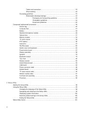
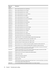
...001 For use in MTV2 artist edition computers 570205-001 Power button board (includes cable) 512834-001 Keyboard (includes keyboard cable) NOTE: For a detailed list of available keyboards, see Sequential part number listing on display assembly spare part numbers. Item (2) (3) (4) (5) ...componentson page 26 for more information on page 31. White painted keyboard 517864-xxx White molded keyboard 517863-xxx Black painted keyboard 518965-xxx Black molded keyboard 518966-xxx Black textured keyboard 570228-xxx Bluetooth module 483113-001 20 Chapter 3 Illustrated parts ...
...001 For use in MTV2 artist edition computers 570205-001 Power button board (includes cable) 512834-001 Keyboard (includes keyboard cable) NOTE: For a detailed list of available keyboards, see Sequential part number listing on display assembly spare part numbers. Item (2) (3) (4) (5) ...componentson page 26 for more information on page 31. White painted keyboard 517864-xxx White molded keyboard 517863-xxx Black painted keyboard 518965-xxx Black molded keyboard 518966-xxx Black textured keyboard 570228-xxx Bluetooth module 483113-001 20 Chapter 3 Illustrated parts ...

Service Guide
Page 43
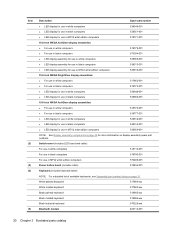
... in Turkey White molded keyboard for use in Latin America White molded keyboard for use in Brazil White molded keyboard for use in Hungary White molded keyboard for use in Russia White molded keyboard for use in Belgium White molded keyboard for use in Taiwan White molded keyboard for use internationally White molded keyboard for use in Greece...
... in Turkey White molded keyboard for use in Latin America White molded keyboard for use in Brazil White molded keyboard for use in Hungary White molded keyboard for use in Russia White molded keyboard for use in Belgium White molded keyboard for use in Taiwan White molded keyboard for use internationally White molded keyboard for use in Greece...

Service Guide
Page 44
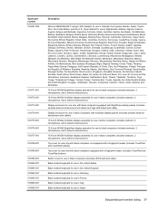
... Czech Republic White painted keyboard for use in Russia White painted keyboard for use in Thailand White painted keyboard for use in Japan White painted keyboard for use in Belgium White painted keyboard for use in Taiwan White painted keyboard for use in South Korea White painted keyboard for use internationally White painted keyboard for use in the...
... Czech Republic White painted keyboard for use in Russia White painted keyboard for use in Thailand White painted keyboard for use in Japan White painted keyboard for use in Belgium White painted keyboard for use in Taiwan White painted keyboard for use in South Korea White painted keyboard for use internationally White painted keyboard for use in the...
Service Guide
Page 45
... computers (includes LED board and cable) Black molded keyboard for use in the United States Black molded keyboard for use in the United Kingdom Black molded keyboard for use in Germany Black molded keyboard for use in France Black molded keyboard for use in Italy Black molded keyboard for use in Spain Sequential part number listing...
... computers (includes LED board and cable) Black molded keyboard for use in the United States Black molded keyboard for use in the United Kingdom Black molded keyboard for use in Germany Black molded keyboard for use in France Black molded keyboard for use in Italy Black molded keyboard for use in Spain Sequential part number listing...
Service Guide
Page 46
... keyboard for use in Japan Black painted keyboard for use in South Korea Black painted keyboard for use in the Netherlands Display Hinge Kit for 15.6-inch AntiGlare displays (includes left and right hinges) AMD Turion Ultra ZM-85 2.30-GHz processor with 2-MB L2 cache AMD Turion RM-75 2.20-GHz processor... with 1-MB L2 cache AMD Athlon QL-65 2.10-GHz processor with ...
... keyboard for use in Japan Black painted keyboard for use in South Korea Black painted keyboard for use in the Netherlands Display Hinge Kit for 15.6-inch AntiGlare displays (includes left and right hinges) AMD Turion Ultra ZM-85 2.30-GHz processor with 2-MB L2 cache AMD Turion RM-75 2.20-GHz processor... with 1-MB L2 cache AMD Athlon QL-65 2.10-GHz processor with ...

Service Guide
Page 47
... use in Saudi Arabia Black textured keyboard for use in Brazil Black textured keyboard for use in Hungary Black textured keyboard for use in the Czech Republic Black textured keyboard for use in Russia Black textured keyboard for use in Thailand Black textured keyboard for use in Japan Black textured keyboard for use internationally Sequential part number...
... use in Saudi Arabia Black textured keyboard for use in Brazil Black textured keyboard for use in Hungary Black textured keyboard for use in the Czech Republic Black textured keyboard for use in Russia Black textured keyboard for use in Thailand Black textured keyboard for use in Japan Black textured keyboard for use internationally Sequential part number...
Service Guide
Page 48
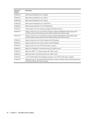
...-001 572566-001 573304-001 573305-001 Description Black textured keyboard for use in Belgium Black textured keyboard for use in Greece Black textured keyboard for use in Taiwan Black textured keyboard for use in South Korea Black textured keyboard for use in the Netherlands System board for use with ... LED displays Display enclosure for use in MTV2 artist edition computers AMD Turion Ultra ZM-87, 2.40-GHz processor with 2-MB L2 cache AMD Turion RM-77, 2.30-GHz processor with 1-MB L2 cache AMD Athlon QL-67, 2.20-GHz processor with 1-MB L2 cache 16.0-inch WXGA BrightView LED display assembly...
...-001 572566-001 573304-001 573305-001 Description Black textured keyboard for use in Belgium Black textured keyboard for use in Greece Black textured keyboard for use in Taiwan Black textured keyboard for use in South Korea Black textured keyboard for use in the Netherlands System board for use with ... LED displays Display enclosure for use in MTV2 artist edition computers AMD Turion Ultra ZM-87, 2.40-GHz processor with 2-MB L2 cache AMD Turion RM-77, 2.30-GHz processor with 1-MB L2 cache AMD Athlon QL-67, 2.20-GHz processor with 1-MB L2 cache 16.0-inch WXGA BrightView LED display assembly...

Service Guide
Page 71
... . Disconnect all external devices connected to the computer. 3. Remove the switch cover and keyboard: 1. Remove the battery (see Sequential part number listing on page 31. Before removing the switch cover and keyboard, follow these steps: 1. Component replacement procedures 63 Description Switch cover for use in white... on, and then shut it down through the operating system. 2. Position the computer upside down the computer. Switch cover and keyboard NOTE: Only select models are equipped with the front toward you are unsure whether the computer is off or in MTV2 artist ...
... . Disconnect all external devices connected to the computer. 3. Remove the switch cover and keyboard: 1. Remove the battery (see Sequential part number listing on page 31. Before removing the switch cover and keyboard, follow these steps: 1. Component replacement procedures 63 Description Switch cover for use in white... on, and then shut it down through the operating system. 2. Position the computer upside down the computer. Switch cover and keyboard NOTE: Only select models are equipped with the front toward you are unsure whether the computer is off or in MTV2 artist ...

Service Guide
Page 72
Lift the rear edge of the switch cover until it detaches from the computer. 64 Chapter 4 Removal and replacement procedures Turn the computer display-side up, with the front toward you. 4. 2. Open the computer as far as possible. 5. Remove the following screws: (1) Two Phillips PM2.5×6.5 screws that secure the switch cover to the computer (2) Three Phillips PM2.5×5.0 screws that secure the switch cover to the computer (inside the battery bay) (3) Four Phillips PM2.5×6.5 screws that secure the keyboard to the computer 3.
Lift the rear edge of the switch cover until it detaches from the computer. 64 Chapter 4 Removal and replacement procedures Turn the computer display-side up, with the front toward you. 4. 2. Open the computer as far as possible. 5. Remove the following screws: (1) Two Phillips PM2.5×6.5 screws that secure the switch cover to the computer (2) Three Phillips PM2.5×5.0 screws that secure the switch cover to the computer (inside the battery bay) (3) Four Phillips PM2.5×6.5 screws that secure the keyboard to the computer 3.

Service Guide
Page 73
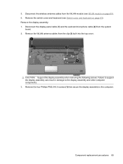
Component replacement procedures 65 Slide the keyboard (2) back until the keyboard connector on the display. 7. Move the switch cover back so it rests on the system board is accessible. Lift the rear edge (1) of the keyboard. 9. 6. Remove the three Phillips PM2.0×3.0 screws that secure the keyboard to the computer. 8.
Component replacement procedures 65 Slide the keyboard (2) back until the keyboard connector on the display. 7. Move the switch cover back so it rests on the system board is accessible. Lift the rear edge (1) of the keyboard. 9. 6. Remove the three Phillips PM2.0×3.0 screws that secure the keyboard to the computer. 8.

Service Guide
Page 74
Disconnect the power button board cable (1) from the LIF connector on the system board. 13. Remove the switch cover. Release the zero insertion force (ZIF) connector (1) to install the switch cover and keyboard. 66 Chapter 4 Removal and replacement procedures Remove the keyboard. 12. Disconnect the LED board cable (2) from the low insertion force (LIF) connector on the system board. 14. Reverse this procedure to which the keyboard cable is connected and disconnect the cable (2) from the system board. 11. 10.
Disconnect the power button board cable (1) from the LIF connector on the system board. 13. Remove the switch cover. Release the zero insertion force (ZIF) connector (1) to install the switch cover and keyboard. 66 Chapter 4 Removal and replacement procedures Remove the keyboard. 12. Disconnect the LED board cable (2) from the low insertion force (LIF) connector on the system board. 14. Reverse this procedure to which the keyboard cable is connected and disconnect the cable (2) from the system board. 11. 10.

Service Guide
Page 75
..., and then shut it down the computer. Disconnect all external devices connected to the computer. 3. Remove the power button board: 1. Remove the switch cover and keyboard (see Battery on page 63). Remove the battery (see Switch cover and...
..., and then shut it down the computer. Disconnect all external devices connected to the computer. 3. Remove the power button board: 1. Remove the switch cover and keyboard (see Battery on page 63). Remove the battery (see Switch cover and...
Service Guide
Page 77
... from the system board. 2. Disconnect the display panel cable (1) and the webcam/microphone cable (2) from the WLAN module (see Switch cover and keyboard on page 60). 6. Remove the four Phillips PM2.5×6.5 screws (1) that secure the display assembly to the display assembly and other computer components.... replacement procedures 69 Remove the WLAN antenna cables from the clip (3) built into the top cover. 5. Remove the switch cover and keyboard (see WLAN module on page 63). Failure to support the display assembly can result in damage to the computer. Remove the display assembly: 1....
... from the system board. 2. Disconnect the display panel cable (1) and the webcam/microphone cable (2) from the WLAN module (see Switch cover and keyboard on page 60). 6. Remove the four Phillips PM2.5×6.5 screws (1) that secure the display assembly to the display assembly and other computer components.... replacement procedures 69 Remove the WLAN antenna cables from the clip (3) built into the top cover. 5. Remove the switch cover and keyboard (see WLAN module on page 63). Failure to support the display assembly can result in damage to the computer. Remove the display assembly: 1....

Service Guide
Page 86
Switch cover and keyboard (see Switch cover and keyboard on page 57) b. Turn the right side up and off or in Hibernation, turn the computer on page 51) c. Disconnect the speaker cable from the ...
Switch cover and keyboard (see Switch cover and keyboard on page 57) b. Turn the right side up and off or in Hibernation, turn the computer on page 51) c. Disconnect the speaker cable from the ...
Service Guide
Page 87
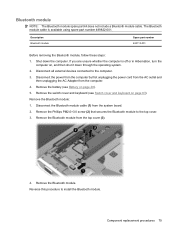
... module to the computer. 3. Shut down through the operating system. 2. Remove the Bluetooth module. Remove the battery (see Switch cover and keyboard on page 63). Component replacement procedures 79 If you are unsure whether the computer is available using spare part number 489822-001. Reverse this... Bluetooth module. Bluetooth module NOTE: The Bluetooth module spare part kit does not include a Bluetooth module cable. Remove the switch cover and keyboard (see Battery on , and then shut it down the computer. The Bluetooth module cable is off or in Hibernation, turn the computer...
... module to the computer. 3. Shut down through the operating system. 2. Remove the Bluetooth module. Remove the battery (see Switch cover and keyboard on page 63). Component replacement procedures 79 If you are unsure whether the computer is available using spare part number 489822-001. Reverse this... Bluetooth module. Bluetooth module NOTE: The Bluetooth module spare part kit does not include a Bluetooth module cable. Remove the switch cover and keyboard (see Battery on , and then shut it down the computer. The Bluetooth module cable is off or in Hibernation, turn the computer...

Service Guide
Page 88
... 518108-001 518789-001 518788-001 570206-001 Before removing the top cover, follow these steps: 1. Switch cover and keyboard (see Display assembly on page 57) b. Display assembly (see Switch cover and keyboard on page 48). 5. Remove the battery (see Battery on page 63) d. Disconnect all external devices connected to the computer...
... 518108-001 518789-001 518788-001 570206-001 Before removing the top cover, follow these steps: 1. Switch cover and keyboard (see Display assembly on page 57) b. Display assembly (see Switch cover and keyboard on page 48). 5. Remove the battery (see Battery on page 63) d. Disconnect all external devices connected to the computer...
Service Guide
Page 91
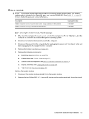
... in Hibernation, turn the computer on page 29 for more Cable Kit spare part number information. Switch cover and keyboard (see Hard drive on page 63). Hard drive (see Switch cover and keyboard on page 57). Remove the modem module: 1. Disconnect the power from the computer by first unplugging the power cord...
... in Hibernation, turn the computer on page 29 for more Cable Kit spare part number information. Switch cover and keyboard (see Hard drive on page 63). Hard drive (see Switch cover and keyboard on page 57). Remove the modem module: 1. Disconnect the power from the computer by first unplugging the power cord...

Service Guide
Page 92
...drive on page 68). Lift the modem module (3) straight up to disconnect it down the computer. Optical drive (see Switch cover and keyboard on page 80). 84 Chapter 4 Removal and replacement procedures e. If you are unsure whether the computer is off or in Hibernation, turn... computers equipped with UMA graphics memory (includes cable) 511892-001 Before removing the audio/infrared board, follow these steps: 1. Switch cover and keyboard (see Optical drive on , and then shut it from the computer. 4. Shut down through the operating system. 2. Disconnect all external devices...
...drive on page 68). Lift the modem module (3) straight up to disconnect it down the computer. Optical drive (see Switch cover and keyboard on page 80). 84 Chapter 4 Removal and replacement procedures e. If you are unsure whether the computer is off or in Hibernation, turn... computers equipped with UMA graphics memory (includes cable) 511892-001 Before removing the audio/infrared board, follow these steps: 1. Switch cover and keyboard (see Optical drive on , and then shut it from the computer. 4. Shut down through the operating system. 2. Disconnect all external devices...


