Service Guide
Page 6
... 44 Workstation guidelines 44 Equipment guidelines 45 Component replacement procedures 46 Service tag ...46 Computer feet ...47 Battery ...48 Webcam/microphone module 49 Optical drive ...51 Memory module ...53 TV tuner module ...55 RTC battery ...56 Hard drive ...57 WLAN module ...60 Switch cover and keyboard 63 Power button board ...67 Display...
... 44 Workstation guidelines 44 Equipment guidelines 45 Component replacement procedures 46 Service tag ...46 Computer feet ...47 Battery ...48 Webcam/microphone module 49 Optical drive ...51 Memory module ...53 TV tuner module ...55 RTC battery ...56 Hard drive ...57 WLAN module ...60 Switch cover and keyboard 63 Power button board ...67 Display...

Service Guide
Page 8
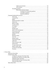
Recovering from the dedicated recovery partition (select models only 139 9 Connector pin assignments 1394 ...140 Audio-in (microphone) ...140 Audio-out (headphone) ...141 External monitor ...141 HDMI ...142 RJ-11 (modem) ...143 RJ-45 (network) ...143 Universal Serial Bus ...144 10 Power cord set requirements Requirements for all countries or regions 145 Requirements for specific countries or regions 146 11 Recycling Battery ...147 Display ...147 Index ...153 viii
Recovering from the dedicated recovery partition (select models only 139 9 Connector pin assignments 1394 ...140 Audio-in (microphone) ...140 Audio-out (headphone) ...141 External monitor ...141 HDMI ...142 RJ-11 (modem) ...143 RJ-45 (network) ...143 Universal Serial Bus ...144 10 Power cord set requirements Requirements for all countries or regions 145 Requirements for specific countries or regions 146 11 Recycling Battery ...147 Display ...147 Index ...153 viii

Service Guide
Page 12
...√ Microphone input (audio-in) √ √ AC adapter plug √ √ Docking Expansion port 3 supports the HP Notebook Expansion Base √ √ and HP Notebook QuickDock Keyboard/pointing devices 16-inch full-size keyboard with numeric keypad √ √ Standard IMR keyboard √ √... √ √ Power requirements 6-cell 2.55-Ah Li-ion battery with target life of 2.5 hours √ 6-cell 2.55-Ah Li-ion battery with target life of 3 hours √ 6-cell 2.20-Ah Li-ion battery with target life of SD, MMC, MS Duo with fourth USB ...
...√ Microphone input (audio-in) √ √ AC adapter plug √ √ Docking Expansion port 3 supports the HP Notebook Expansion Base √ √ and HP Notebook QuickDock Keyboard/pointing devices 16-inch full-size keyboard with numeric keypad √ √ Standard IMR keyboard √ √... √ √ Power requirements 6-cell 2.55-Ah Li-ion battery with target life of 2.5 hours √ 6-cell 2.55-Ah Li-ion battery with target life of 3 hours √ 6-cell 2.20-Ah Li-ion battery with target life of SD, MMC, MS Duo with fourth USB ...
Service Guide
Page 13
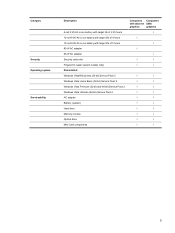
Category Security Operating system Serviceability Description 6-cell 2.20-Ah Li-ion battery with target life of 2.25 hours 12-cell 8.80-Ah Li-ion battery with target life of 4 hours 12-cell 8.80-Ah Li-ion battery with target life of 5 hours 90-W AC adapter 65-W AC ...(32-bit) Service Pack 2 Windows Vista Premium (32-bit and-64 bit) Service Pack 2 Windows Vista Ultimate (64-bit) Service Pack 2 AC adapter Battery (system) Hard drive Memory module Optical drive Mini Card components Computers Computers with discrete UMA graphics graphics √ √ √ √ √ √...
Category Security Operating system Serviceability Description 6-cell 2.20-Ah Li-ion battery with target life of 2.25 hours 12-cell 8.80-Ah Li-ion battery with target life of 4 hours 12-cell 8.80-Ah Li-ion battery with target life of 5 hours 90-W AC adapter 65-W AC ...(32-bit) Service Pack 2 Windows Vista Premium (32-bit and-64 bit) Service Pack 2 Windows Vista Ultimate (64-bit) Service Pack 2 AC adapter Battery (system) Hard drive Memory module Optical drive Mini Card components Computers Computers with discrete UMA graphics graphics √ √ √ √ √ √...
Service Guide
Page 15
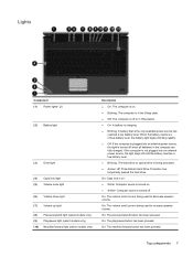
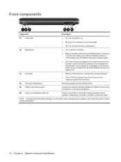
...speaker volume. Top components 7 On: The volume scroll zone is being accessed. ● Amber: HP ProtectSmart Hard Drive Protection has temporarily parked the hard drive. Lights Component (1) Power lights* (2) (2) Battery light (3) Drive light (4) Caps lock light (5) Volume mute light (6) Volume down light (7) ...optical drive is plugged into an external power source, the light stays off when all batteries in the computer are fully charged. When the battery reaches a critical battery level, the battery light begins blinking rapidly. ● Off: If the computer is being used to ...
...speaker volume. Top components 7 On: The volume scroll zone is being accessed. ● Amber: HP ProtectSmart Hard Drive Protection has temporarily parked the hard drive. Lights Component (1) Power lights* (2) (2) Battery light (3) Drive light (4) Caps lock light (5) Volume mute light (6) Volume down light (7) ...optical drive is plugged into an external power source, the light stays off when all batteries in the computer are fully charged. When the battery reaches a critical battery level, the battery light begins blinking rapidly. ● Off: If the computer is being used to ...
Service Guide
Page 20
...describes factory settings. If the computer is not plugged into an external power source, the light is being accessed. ● Amber: HP ProtectSmart Hard Drive Protection has temporarily parked the hard drive. (4) Consumer infrared lens Receives a signal from the remote control. (5) Audio... sound when connected to the user guides located in Help and Support. 12 Chapter 2 External component identification When the battery reaches a critical battery level, the battery light begins blinking rapidly. ● Off: If the computer is plugged into an external power source, the light stays...
...describes factory settings. If the computer is not plugged into an external power source, the light is being accessed. ● Amber: HP ProtectSmart Hard Drive Protection has temporarily parked the hard drive. (4) Consumer infrared lens Receives a signal from the remote control. (5) Audio... sound when connected to the user guides located in Help and Support. 12 Chapter 2 External component identification When the battery reaches a critical battery level, the battery light begins blinking rapidly. ● Off: If the computer is plugged into an external power source, the light stays...
Service Guide
Page 23
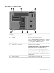
... for use in the computer by the governmental agency that regulates wireless devices in your country or region. Releases the battery from the battery bay. CAUTION: To prevent an unresponsive system, replace the wireless module only with a wireless module authorized for the ... the module to cycle on and off during routine operation. Bottom components Component (1) Hard drive bay (2) Vents (8) (3) Battery bay (4) Memory module compartment (5) Battery release latch Description Holds the hard drive. Contains the memory module slots. Also holds the WLAN module, TV tuner card ...
... for use in the computer by the governmental agency that regulates wireless devices in your country or region. Releases the battery from the battery bay. CAUTION: To prevent an unresponsive system, replace the wireless module only with a wireless module authorized for the ... the module to cycle on and off during routine operation. Bottom components Component (1) Hard drive bay (2) Vents (8) (3) Battery bay (4) Memory module compartment (5) Battery release latch Description Holds the hard drive. Contains the memory module slots. Also holds the WLAN module, TV tuner card ...

Service Guide
Page 33
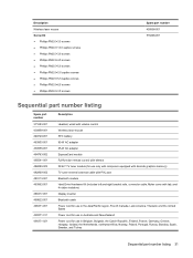
... Rubber Feet Kit (not illustrated, includes 4 base enclosure rubber feet) 516499-001 Battery 12-cell, 95-Wh, 8.8-Ah Li-ion battery 509460-001 6-cell, 55-Wh, 2.55-Ah Li-ion battery 509459-001 6-cell, 47-Wh, 2.20-Ah Li-ion battery 509458-001 Optical drive (includes bezel and bracket) DVD±RW and CD... Drive 509420-002 Blu-ray ROM with discrete graphics 482899-003 memory) TV tuner external antenna cable (not illustrated) With PAL jack 482900-002 RTC battery 449729-001 Computer major components 25
... Rubber Feet Kit (not illustrated, includes 4 base enclosure rubber feet) 516499-001 Battery 12-cell, 95-Wh, 8.8-Ah Li-ion battery 509460-001 6-cell, 55-Wh, 2.55-Ah Li-ion battery 509459-001 6-cell, 47-Wh, 2.20-Ah Li-ion battery 509458-001 Optical drive (includes bezel and bracket) DVD±RW and CD... Drive 509420-002 Blu-ray ROM with discrete graphics 482899-003 memory) TV tuner external antenna cable (not illustrated) With PAL jack 482900-002 RTC battery 449729-001 Computer major components 25
Service Guide
Page 39
...-002 483113-001 483862-001 488317-001 489822-001 490371-001 490371-011 490371-021 Description Headset, wired with volume control Wireless laser mouse RTC battery 90-W AC adapter 65-W AC adapter ExpressCard module Full-function remote control with teletext DVB-T TV tuner module (for use only with computers equipped with...
...-002 483113-001 483862-001 488317-001 489822-001 490371-001 490371-011 490371-021 Description Headset, wired with volume control Wireless laser mouse RTC battery 90-W AC adapter 65-W AC adapter ExpressCard module Full-function remote control with teletext DVB-T TV tuner module (for use only with computers equipped with...

Service Guide
Page 42
... memory and 512 MB of dedicated memory (includes replacement thermal material) 6-cell, 47-Wh, 2.20-Ah Li-ion battery 6-cell, 55-Wh, 2.55-Ah Li-ion battery 12-cell, 95-Wh, 8.8-Ah Li-ion battery Modem module for use in all countries and regions except Australia and New Zealand Modem module for use...
... memory and 512 MB of dedicated memory (includes replacement thermal material) 6-cell, 47-Wh, 2.20-Ah Li-ion battery 6-cell, 55-Wh, 2.55-Ah Li-ion battery 12-cell, 95-Wh, 8.8-Ah Li-ion battery Modem module for use in all countries and regions except Australia and New Zealand Modem module for use...

Service Guide
Page 56
...operating system. 2. To insert the battery, insert the rear edge of the battery downward until it from the computer. Battery Description 12-cell, 95-Wh, 8.8-Ah Li-ion battery 6-cell, 55-Wh, 2.55-Ah Li-ion battery 6-cell, 47-Wh, 2.20-Ah Li-ion battery Spare part number 509460-001 509459-...and remove it is off or in Hibernation, turn the computer on a flat surface. 2. The battery release latch automatically locks the battery into the battery bay and pivot the front edge of the battery into place. 48 Chapter 4 Removal and replacement procedures If you are unsure whether the computer is...
...operating system. 2. To insert the battery, insert the rear edge of the battery downward until it from the computer. Battery Description 12-cell, 95-Wh, 8.8-Ah Li-ion battery 6-cell, 55-Wh, 2.55-Ah Li-ion battery 6-cell, 47-Wh, 2.20-Ah Li-ion battery Spare part number 509460-001 509459-...and remove it is off or in Hibernation, turn the computer on a flat surface. 2. The battery release latch automatically locks the battery into the battery bay and pivot the front edge of the battery into place. 48 Chapter 4 Removal and replacement procedures If you are unsure whether the computer is...
Service Guide
Page 57
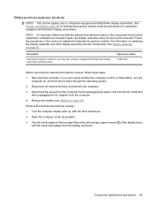
For information on replacing the display assembly and other display assembly internal components, see Battery on page 48). Open the computer as far as possible. 3. See Display assemblyon page 68 for webcam/microphone module removal instructions for use only ...and right upper corners (2) of the display bezel until the bezel disengages from the computer. 4. Disconnect all external devices connected to the computer. 3. Remove the battery (see Display assembly on , and then shut it has been determined that the webcam/microphone module is off or in this section to be removed.
For information on replacing the display assembly and other display assembly internal components, see Battery on page 48). Open the computer as far as possible. 3. See Display assemblyon page 68 for webcam/microphone module removal instructions for use only ...and right upper corners (2) of the display bezel until the bezel disengages from the computer. 4. Disconnect all external devices connected to the computer. 3. Remove the battery (see Display assembly on , and then shut it has been determined that the webcam/microphone module is off or in this section to be removed.

Service Guide
Page 59
... tray release access hole (2). (The optical drive disc tray is necessary to the computer. 3. Remove the optical drive. 6. Remove the optical drive: 1. Remove the battery (see Battery on , and then shut it is partially ejected from the computer. 4. Remove the Phillips PM2.5×6.5 screw (1) that secures the optical drive to replace the...
... tray release access hole (2). (The optical drive disc tray is necessary to the computer. 3. Remove the optical drive. 6. Remove the optical drive: 1. Remove the battery (see Battery on , and then shut it is partially ejected from the computer. 4. Remove the Phillips PM2.5×6.5 screw (1) that secures the optical drive to replace the...

Service Guide
Page 61
..., turn the computer on page 48). The memory module compartment cover is off or in the Plastics Kit, spare part number 511890-001. 4. Remove the battery (see Battery on , and then shut it up and to the computer. 3. Lift the rear edge (2) of the cover, swing it down the computer. Disconnect all...
..., turn the computer on page 48). The memory module compartment cover is off or in the Plastics Kit, spare part number 511890-001. 4. Remove the battery (see Battery on , and then shut it up and to the computer. 3. Lift the rear edge (2) of the cover, swing it down the computer. Disconnect all...

Service Guide
Page 63
Shut down through the operating system. 2. Disconnect all external devices connected to the computer. 3. Remove the battery (see Memory module on page 48). 5. If you are unsure whether the computer is included in Hibernation, turn the computer on the TV ...module to the computer. 3. Reverse this procedure to prevent incorrect insertion into the TV tuner module slot. Remove the memory module compartment cover (see Battery on page 53). Component replacement procedures 55 Disconnect the TV tuner module antenna cable (1) from the terminal on , and then shut it down ...
Shut down through the operating system. 2. Disconnect all external devices connected to the computer. 3. Remove the battery (see Memory module on page 48). 5. If you are unsure whether the computer is included in Hibernation, turn the computer on the TV ...module to the computer. 3. Reverse this procedure to prevent incorrect insertion into the TV tuner module slot. Remove the memory module compartment cover (see Battery on page 53). Component replacement procedures 55 Disconnect the TV tuner module antenna cable (1) from the terminal on , and then shut it down ...

Service Guide
Page 64
... are unsure whether the computer is installed with the "+" sign facing up. 56 Chapter 4 Removal and replacement procedures Reverse this procedure to install the RTC battery. Disconnect the power from the computer by first unplugging the power cord from the AC outlet and then unplugging the AC adapter from the socket... on page 53). Be sure that the RTC battery is off or in Hibernation, turn the computer on page 48). 5. Shut down through the operating system. 2. RTC...
... are unsure whether the computer is installed with the "+" sign facing up. 56 Chapter 4 Removal and replacement procedures Reverse this procedure to install the RTC battery. Disconnect the power from the computer by first unplugging the power cord from the AC outlet and then unplugging the AC adapter from the socket... on page 53). Be sure that the RTC battery is off or in Hibernation, turn the computer on page 48). 5. Shut down through the operating system. 2. RTC...

Service Guide
Page 65
... power from the computer by first unplugging the power cord from the AC outlet and then unplugging the AC adapter from the computer. 4. Remove the battery (see Battery on , and then shut it down the computer. Loosen the two Phillips PM2.5×5.5 captive screws (1) that secure the hard drive cover to the...
... power from the computer by first unplugging the power cord from the AC outlet and then unplugging the AC adapter from the computer. 4. Remove the battery (see Battery on , and then shut it down the computer. Loosen the two Phillips PM2.5×5.5 captive screws (1) that secure the hard drive cover to the...
Service Guide
Page 70
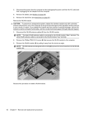
... procedures The white WLAN antenna cable is connected to restore computer functionality, and then contact technical support through Help and Support. 1. Remove the battery (see Hard drive on page 48). 5. Disconnect the WLAN antenna cables (1) from the computer. 4. Remove the WLAN module (3) by the... terminal. 2. Remove the Phillips PM2.0×3.0 screw (2) that regulates wireless devices in your country or region. Remove the hard drive (see Battery on page 57). NOTE: WLAN modules are designed with a wireless module authorized for use in the computer by pulling it away from the...
... procedures The white WLAN antenna cable is connected to restore computer functionality, and then contact technical support through Help and Support. 1. Remove the battery (see Hard drive on page 48). 5. Disconnect the WLAN antenna cables (1) from the computer. 4. Remove the WLAN module (3) by the... terminal. 2. Remove the Phillips PM2.0×3.0 screw (2) that regulates wireless devices in your country or region. Remove the hard drive (see Battery on page 57). NOTE: WLAN modules are designed with a wireless module authorized for use in the computer by pulling it away from the...

Service Guide
Page 71
...from the computer by first unplugging the power cord from the AC outlet and then unplugging the AC adapter from the computer. 4. Remove the battery (see Sequential part number listing on , and then shut it down the computer. Switch cover and keyboard NOTE: Only select models are ... Black painted keyboard 518966-xxx Black molded keyboard 518965-xxx Black textured keyboard 570228-xxx NOTE: For a detailed list of available keyboards, see Battery on the switch cover. Remove the switch cover and keyboard: 1. If you are equipped with the front toward you. Before removing the switch...
...from the computer by first unplugging the power cord from the AC outlet and then unplugging the AC adapter from the computer. 4. Remove the battery (see Sequential part number listing on , and then shut it down the computer. Switch cover and keyboard NOTE: Only select models are ... Black painted keyboard 518966-xxx Black molded keyboard 518965-xxx Black textured keyboard 570228-xxx NOTE: For a detailed list of available keyboards, see Battery on the switch cover. Remove the switch cover and keyboard: 1. If you are equipped with the front toward you. Before removing the switch...

Service Guide
Page 72
Open the computer as far as possible. 5. Lift the rear edge of the switch cover until it detaches from the computer. 64 Chapter 4 Removal and replacement procedures 2. Turn the computer display-side up, with the front toward you. 4. Remove the following screws: (1) Two Phillips PM2.5×6.5 screws that secure the switch cover to the computer (2) Three Phillips PM2.5×5.0 screws that secure the switch cover to the computer (inside the battery bay) (3) Four Phillips PM2.5×6.5 screws that secure the keyboard to the computer 3.
Open the computer as far as possible. 5. Lift the rear edge of the switch cover until it detaches from the computer. 64 Chapter 4 Removal and replacement procedures 2. Turn the computer display-side up, with the front toward you. 4. Remove the following screws: (1) Two Phillips PM2.5×6.5 screws that secure the switch cover to the computer (2) Three Phillips PM2.5×5.0 screws that secure the switch cover to the computer (inside the battery bay) (3) Four Phillips PM2.5×6.5 screws that secure the keyboard to the computer 3.


