
HP DesignJet 5000 Series Printer - Pocket Guide
Page 113
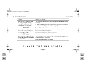
Remove the electrical connector from the rear of the ink cartridge tube connector. Rotate the three latches at the rear of the ink cartridge tube connector. CHANGE THE INK SYSTEM file:///D|/hydra/ug_loc/f Ink System Removal 11. pocket.book Page 111 Sunday, October 29, 2000 5:09 PM 111 - Change The Ink System 10. This will release the complete assembly.
Remove the electrical connector from the rear of the ink cartridge tube connector. Rotate the three latches at the rear of the ink cartridge tube connector. CHANGE THE INK SYSTEM file:///D|/hydra/ug_loc/f Ink System Removal 11. pocket.book Page 111 Sunday, October 29, 2000 5:09 PM 111 - Change The Ink System 10. This will release the complete assembly.

HP DesignJet 5000 Series Printer - Pocket Guide
Page 114
pocket.book Page 112 Sunday, October 29, 2000 5:09 PM 112 - Remove the ink cartridge tube connector from the printer. file:///D|/hydra/ug_loc/f You will not be removed from the rear of the left hand side. Ink System Removal NOTE: Carefully place the removed tubes in the open window until you can now be able to do this until you have ink tubes that are already in the HP Ink Tubes Container. The complete assembly can store them in the container into the printer. 13. Change The Ink System 12.
pocket.book Page 112 Sunday, October 29, 2000 5:09 PM 112 - Remove the ink cartridge tube connector from the printer. file:///D|/hydra/ug_loc/f You will not be removed from the rear of the left hand side. Ink System Removal NOTE: Carefully place the removed tubes in the open window until you can now be able to do this until you have ink tubes that are already in the HP Ink Tubes Container. The complete assembly can store them in the container into the printer. 13. Change The Ink System 12.

HP DesignJet 5000 Series Printer - Pocket Guide
Page 117
This will lock the complete assembly into place. pocket.book Page 115 Sunday, October 29, 2000 5:09 PM 115 - Change The Ink System 3. Ink System Installation 4. CHANGE THE INK SYSTEM file:///D|/hydra/ug_loc/f Rotate the three latches at the rear of the ink cartridge tube connector by pushing down on the latch and inserting the tube. Connect the air tube to the rear of the ink cartridge tube connector.
This will lock the complete assembly into place. pocket.book Page 115 Sunday, October 29, 2000 5:09 PM 115 - Change The Ink System 3. Ink System Installation 4. CHANGE THE INK SYSTEM file:///D|/hydra/ug_loc/f Rotate the three latches at the rear of the ink cartridge tube connector by pushing down on the latch and inserting the tube. Connect the air tube to the rear of the ink cartridge tube connector.

HP DesignJet 5000 Series Printer - Pocket Guide
Page 121
Install the tubes to the the carriage CHANGE THE INK SYSTEM file:///D|/hydra/ug_loc/f Slide the assembly to the right until it is locked to the carriage as shown below. Change The Ink System Ink System Installation 11. pocket.book Page 119 Sunday, October 29, 2000 5:09 PM 119 -
Install the tubes to the the carriage CHANGE THE INK SYSTEM file:///D|/hydra/ug_loc/f Slide the assembly to the right until it is locked to the carriage as shown below. Change The Ink System Ink System Installation 11. pocket.book Page 119 Sunday, October 29, 2000 5:09 PM 119 -

HP DesignJet 5000 Series Printer - Pocket Guide
Page 122
Change The Ink System 12. file:///D|/hydra/ug_loc/f pocket.book Page 120 Sunday, October 29, 2000 5:09 PM 120 - Ink System Installation 13.Carefully place the previously removed ink tubes in the HP Ink Tubes container (see Using the Printheads and Ink Tubes Containers, on page 135). Install the printhead tube connector onto the carriage assembly.
Change The Ink System 12. file:///D|/hydra/ug_loc/f pocket.book Page 120 Sunday, October 29, 2000 5:09 PM 120 - Ink System Installation 13.Carefully place the previously removed ink tubes in the HP Ink Tubes container (see Using the Printheads and Ink Tubes Containers, on page 135). Install the printhead tube connector onto the carriage assembly.
HP DesignJet 5000 Series Printer - Pocket Guide
Page 135
.... Insert the correct type of printhead cleaners. CHANGE THE INK SYSTEM file:///D|/hydra/ug_loc/f a Make sure the printhead tube connector is not correctly connected the carriage assembly. You cannot insert a printhead into the carriage assembly labelled with the same color. b Insert the printheads. Change The Ink System Troubleshooting Problem Reason and solution When you try...
.... Insert the correct type of printhead cleaners. CHANGE THE INK SYSTEM file:///D|/hydra/ug_loc/f a Make sure the printhead tube connector is not correctly connected the carriage assembly. You cannot insert a printhead into the carriage assembly labelled with the same color. b Insert the printheads. Change The Ink System Troubleshooting Problem Reason and solution When you try...

HP DesignJet 5000 Series Printer - Pocket Guide
Page 160
...Ink tube maintenance required now Insert Insert cleaner Insert ink cartridges Insert printhead Front Panel Messages Description Procedure The need cleaning. This is no consumable installed The printhead cleaners are located on page 85 file:///D|/hydra/ug_loc/f Insert the correct printhead(s) into the carriage assembly Contact your HP.... See page 63, in section The Ink Supply on -site visit to insert a printhead into the carriage assembly. There is an ink cartridge removal instruction. Check the interconnect to change the ink tubes may affect the performance of the printer....
...Ink tube maintenance required now Insert Insert cleaner Insert ink cartridges Insert printhead Front Panel Messages Description Procedure The need cleaning. This is no consumable installed The printhead cleaners are located on page 85 file:///D|/hydra/ug_loc/f Insert the correct printhead(s) into the carriage assembly Contact your HP.... See page 63, in section The Ink Supply on -site visit to insert a printhead into the carriage assembly. There is an ink cartridge removal instruction. Check the interconnect to change the ink tubes may affect the performance of the printer....

HP Designjet 5000 series printer - User's Guide
Page 157
... you to insert a printhead into the carriage assembly. Check the interconnect to change the ink tubes may affect the performance of the printer. The need to see Ink Cartridge Installation See Printhead Installation Insert the correct printhead(s) into the carriage assembly Procedure At your earliest convenience contact your HP representative to arrange for an on -site...
... you to insert a printhead into the carriage assembly. Check the interconnect to change the ink tubes may affect the performance of the printer. The need to see Ink Cartridge Installation See Printhead Installation Insert the correct printhead(s) into the carriage assembly Procedure At your earliest convenience contact your HP representative to arrange for an on -site...
Service Manual
Page 5
...Ink Supplies Error Codes 1-4 Troubleshooting Initialization - Table of Contents Table of tubes system" 1-17 User message "Power Supply Error #1" 1-17 Cutter Assembly Problems 1-19 Carriage and Scan-Axis Problems 1-20 Media-Axis Problems 1-20 Electronics Problems 1-21 Language Selection is blocked in different HP DesignJet... Exchanging the Ink Tubes 1-24 Solving Media-Handling Problems 1-25 How to Navigate through the Front Panel Menus 1-26 Service Configuration Print 1-37 General Printer Information 1-39 Troubleshooting Take-Up-Reel Problems 1-40 HP DesignJet 5000 Series Printers Service...
...Ink Supplies Error Codes 1-4 Troubleshooting Initialization - Table of Contents Table of tubes system" 1-17 User message "Power Supply Error #1" 1-17 Cutter Assembly Problems 1-19 Carriage and Scan-Axis Problems 1-20 Media-Axis Problems 1-20 Electronics Problems 1-21 Language Selection is blocked in different HP DesignJet... Exchanging the Ink Tubes 1-24 Solving Media-Handling Problems 1-25 How to Navigate through the Front Panel Menus 1-26 Service Configuration Print 1-37 General Printer Information 1-39 Troubleshooting Take-Up-Reel Problems 1-40 HP DesignJet 5000 Series Printers Service...
Service Manual
Page 9
...Vacuum Fan 7-14 Booster Fan and Media Sensor 7-16 Paper-Axis Motor 7-18 Scan-Axis Motor 7-20 ISS and APS Assembly 7-22 Ink Tubes System 7-24 Boot ROM DIMM, DRAM Memory and Covers 7-26 Rear Electronics Access Covers 7-28 Hard Disk Drive and Cover ...Safety Precautions 8-2 Electrostatic Discharge (ESD) Precautions 8-3 Required Tools 8-3 Screw Types 8-4 Top Cover Assembly 8-5 Left Hand Cover 8-6 Right Hand Cover 8-10 Front Panel Assembly 8-14 Left Rear Cover 8-15 Right Rear Cover 8-16 Extension Cover (60" Model only) 8-17 Media Lever Assembly 8-18 HP DesignJet 5000 Series Printers Service Manual 7
...Vacuum Fan 7-14 Booster Fan and Media Sensor 7-16 Paper-Axis Motor 7-18 Scan-Axis Motor 7-20 ISS and APS Assembly 7-22 Ink Tubes System 7-24 Boot ROM DIMM, DRAM Memory and Covers 7-26 Rear Electronics Access Covers 7-28 Hard Disk Drive and Cover ...Safety Precautions 8-2 Electrostatic Discharge (ESD) Precautions 8-3 Required Tools 8-3 Screw Types 8-4 Top Cover Assembly 8-5 Left Hand Cover 8-6 Right Hand Cover 8-10 Front Panel Assembly 8-14 Left Rear Cover 8-15 Right Rear Cover 8-16 Extension Cover (60" Model only) 8-17 Media Lever Assembly 8-18 HP DesignJet 5000 Series Printers Service Manual 7
Service Manual
Page 10
... Ink Leak Detector 8-86 Cooling Fans 8-88 Electronics Module (as one complete Assembly) 8-90 Pinch-Wheels 8-91 Pinch-Wheel Cam 8-93 Vacuum Fan 8-96 Paper-Axis Motor Assembly 8-98 Booster Fan 8-101 Media Sensor 8-102 Entry Roller 8-104 Center Guide Assembly 8-105 Drive Roller Gear 8-107 Front Platen Assembly 8-108 Center Platen Assembly 8-110 Deflectors 8-112 8 HP DesignJet 5000...
... Ink Leak Detector 8-86 Cooling Fans 8-88 Electronics Module (as one complete Assembly) 8-90 Pinch-Wheels 8-91 Pinch-Wheel Cam 8-93 Vacuum Fan 8-96 Paper-Axis Motor Assembly 8-98 Booster Fan 8-101 Media Sensor 8-102 Entry Roller 8-104 Center Guide Assembly 8-105 Drive Roller Gear 8-107 Front Platen Assembly 8-108 Center Platen Assembly 8-110 Deflectors 8-112 8 HP DesignJet 5000...

Service Manual
Page 13
... Typical Failures After Exchanging the Ink Tubes 1-24 Solving Media-Handling Problems 1-25 How to Which Ink System 1-2 Troubleshooting System Error Codes...Assembly 1-3 Performing the Necessary Service Calibrations 1-3 Troubleshooting Calibration Error Codes 1-3 Troubleshooting Ink Supplies Error Codes 1-4 Troubleshooting Initialization - Troubleshooting 1 Introduction 1-2 Phone Support 1-2 Which Firmware Version Relates to Navigate through the Front Panel Menus 1-26 Service Configuration Print 1-37 General Printer Information 1-39 Troubleshooting Take-Up-Reel Problems 1-40 HP DesignJet 5000...
... Typical Failures After Exchanging the Ink Tubes 1-24 Solving Media-Handling Problems 1-25 How to Which Ink System 1-2 Troubleshooting System Error Codes...Assembly 1-3 Performing the Necessary Service Calibrations 1-3 Troubleshooting Calibration Error Codes 1-3 Troubleshooting Ink Supplies Error Codes 1-4 Troubleshooting Initialization - Troubleshooting 1 Introduction 1-2 Phone Support 1-2 Which Firmware Version Relates to Navigate through the Front Panel Menus 1-26 Service Configuration Print 1-37 General Printer Information 1-39 Troubleshooting Take-Up-Reel Problems 1-40 HP DesignJet 5000...
Service Manual
Page 29
...the leading edge of the Ink Tubes System is connected to the ISS PCA. To verify this message appears after the Tubes have been a bad HP DesignJet 5000 Series Printers Service Manual 1-17 If the message comes up correctly. In this fails, replace the Carriage Assembly ⇒ Page 8-46...replaced). User message "Power Supply Error #1" This error indicates a short in the Ink Tubes System or ISS PCA. Troubleshooting 2. n If the Printer powers up during the loading process, the Lens Cover Assembly is either not installed correctly or it is defective. To verify this , try the...
...the leading edge of the Ink Tubes System is connected to the ISS PCA. To verify this message appears after the Tubes have been a bad HP DesignJet 5000 Series Printers Service Manual 1-17 If the message comes up correctly. In this fails, replace the Carriage Assembly ⇒ Page 8-46...replaced). User message "Power Supply Error #1" This error indicates a short in the Ink Tubes System or ISS PCA. Troubleshooting 2. n If the Printer powers up during the loading process, the Lens Cover Assembly is either not installed correctly or it is defective. To verify this , try the...

Service Manual
Page 36
... When you try to print, the Front Panel displays: System Error 0a0000 00000002 Contact HP Representative The air tube has not been correctly connected to prime the Ink Tubes. 1 Insert the Setup Printheads provided with the HP Upgrade Kit that they are of the same type as the rest of the Left Hand... more Printhead: XX02 Reseat The three latches at the back of the consumables (No.81 or No.83). 3 Replace the incorrect ones. 1-24 HP DesignJet 5000 Series Printers Service Manual When you try to insert an Ink Cartridge, you try to the Carriage Assembly. 3 Insert the Printheads.
... When you try to print, the Front Panel displays: System Error 0a0000 00000002 Contact HP Representative The air tube has not been correctly connected to prime the Ink Tubes. 1 Insert the Setup Printheads provided with the HP Upgrade Kit that they are of the same type as the rest of the Left Hand... more Printhead: XX02 Reseat The three latches at the back of the consumables (No.81 or No.83). 3 Replace the incorrect ones. 1-24 HP DesignJet 5000 Series Printers Service Manual When you try to insert an Ink Cartridge, you try to the Carriage Assembly. 3 Insert the Printheads.

Service Manual
Page 197
...12 Vacuum Fan 7-14 Booster Fan and Media Sensor 7-16 Paper-Axis Motor 7-18 Scan-Axis Motor 7-20 ISS and APS Assembly 7-22 Ink Tubes System 7-24 Boot ROM DIMM, DRAM Memory and Covers 7-26 Rear Electronics Access Covers 7-28 Hard Disk Drive and Cover 7-30... Supply Unit 7-34 Carriage Assembly 7-36 Tensioner Assembly and Encoder Strip 7-38 Platen Assemblies 7-40 Pinch-Wheels Assembly and Lever 7-42 Center Guide, Deflector and Entry Roller 7-44 Tubes Guide Assemblies 7-46 EMC Covers 7-48 Spindle and Hub 7-50 Miscellaneous Items 7-52 Media Types 7-53 HP DesignJet 5000 Series Printers Service Manual ...
...12 Vacuum Fan 7-14 Booster Fan and Media Sensor 7-16 Paper-Axis Motor 7-18 Scan-Axis Motor 7-20 ISS and APS Assembly 7-22 Ink Tubes System 7-24 Boot ROM DIMM, DRAM Memory and Covers 7-26 Rear Electronics Access Covers 7-28 Hard Disk Drive and Cover 7-30... Supply Unit 7-34 Carriage Assembly 7-36 Tensioner Assembly and Encoder Strip 7-38 Platen Assemblies 7-40 Pinch-Wheels Assembly and Lever 7-42 Center Guide, Deflector and Entry Roller 7-44 Tubes Guide Assemblies 7-46 EMC Covers 7-48 Spindle and Hub 7-50 Miscellaneous Items 7-52 Media Types 7-53 HP DesignJet 5000 Series Printers Service Manual ...
Service Manual
Page 251
... Ink Leak Detector 8-88 Cooling Fans 8-90 Electronics Module (as one complete Assembly) 8-92 Pinch-Wheels 8-93 Pinch-Wheel Cam 8-95 Vacuum Fan 8-98 Paper-Axis Motor Assembly 8-100 Booster Fan 8-103 Media Sensor 8-104 Entry Roller 8-106 Center Guide Assembly 8-107 Drive Roller Gear 8-109 Front Platen Assembly 8-110 Center Platen Assembly 8-112 Deflectors 8-114 HP DesignJet 5000...
... Ink Leak Detector 8-88 Cooling Fans 8-90 Electronics Module (as one complete Assembly) 8-92 Pinch-Wheels 8-93 Pinch-Wheel Cam 8-95 Vacuum Fan 8-98 Paper-Axis Motor Assembly 8-100 Booster Fan 8-103 Media Sensor 8-104 Entry Roller 8-106 Center Guide Assembly 8-107 Drive Roller Gear 8-109 Front Platen Assembly 8-110 Center Platen Assembly 8-112 Deflectors 8-114 HP DesignJet 5000...

Service Manual
Page 280
...assembly can now be removed by sliding the Ink Cartridge Connector out from the rear of the Left Cover and before powering On the printer, check again that the Tubes are replacing. 8-30 HP DesignJet 5000 Series Printers Service Manual NOTE Before installing the new Ink Tubes System, make sure that the Ink Type (Dye or UV) of Ink Tubes... System WARNING When installing the Ink Tubes System it is...
...assembly can now be removed by sliding the Ink Cartridge Connector out from the rear of the Left Cover and before powering On the printer, check again that the Tubes are replacing. 8-30 HP DesignJet 5000 Series Printers Service Manual NOTE Before installing the new Ink Tubes System, make sure that the Ink Type (Dye or UV) of Ink Tubes... System WARNING When installing the Ink Tubes System it is...
Service Manual
Page 397
...List 7-24 Removal 8-25 Installation Air Pressurization System 8-66 Carriage Assembly and Belt 8-52 Center Platen Assembly 8-113 Encoder Strip 8-35 Hard Disk Drive 8-73 Ink Supply Station 8-64 Ink Tubes System 8-30 Left Hand Cover 8-9 Lever Assembly 8-19 Media Sensor 8-105 Memory DIMM 8-76 Overdrive Gear 8-...Wheel Cam 8-97 Right Hand Cover 8-13 Right Hand Trim 8-21 Scan-Axis Motor 8-58 Tensioner Assembly 8-45 Trailing Cable 8-39 Vacuum Fan 8-99 Interface Specifications 10-13 ISS see Ink Supply Station ISS PCA see Ink Supply Station PCA HP DesignJet 5000 Series Printers Service Manual Index-3
...List 7-24 Removal 8-25 Installation Air Pressurization System 8-66 Carriage Assembly and Belt 8-52 Center Platen Assembly 8-113 Encoder Strip 8-35 Hard Disk Drive 8-73 Ink Supply Station 8-64 Ink Tubes System 8-30 Left Hand Cover 8-9 Lever Assembly 8-19 Media Sensor 8-105 Memory DIMM 8-76 Overdrive Gear 8-...Wheel Cam 8-97 Right Hand Cover 8-13 Right Hand Trim 8-21 Scan-Axis Motor 8-58 Tensioner Assembly 8-45 Trailing Cable 8-39 Vacuum Fan 8-99 Interface Specifications 10-13 ISS see Ink Supply Station ISS PCA see Ink Supply Station PCA HP DesignJet 5000 Series Printers Service Manual Index-3
Service Manual
Page 399
...Assembly 7-38 Banding and Media Advance 6-9 Top Cover 7-10 Blurred Lines 6-18 Tubes Guide 7-46 Carriage and Scan-Axis 1-20 User Maintenance Kit 7-52 Color Accuracy 6-17 Vacuum Fan 7-14 Color Alignment 6-11 PCA Color Consistency 6-17 ISS Color not as expected 6-19 Parts List 7-32 Color to Color Alignment 6-19 HP DesignJet 5000... 7-44 Parts List 7-34 Firmware Upgrade CD 7-52 Removal 8-83 Front Panel Assembly 7-6 Priming the Ink System 3-5 HDD and Cover 7-30 Print Modes 6-3 Ink Tubes System 7-24 Print Quality ISS 7-22 Troubleshooting Checklist 6-2 ISS PCA 7-32 Printable...
...Assembly 7-38 Banding and Media Advance 6-9 Top Cover 7-10 Blurred Lines 6-18 Tubes Guide 7-46 Carriage and Scan-Axis 1-20 User Maintenance Kit 7-52 Color Accuracy 6-17 Vacuum Fan 7-14 Color Alignment 6-11 PCA Color Consistency 6-17 ISS Color not as expected 6-19 Parts List 7-32 Color to Color Alignment 6-19 HP DesignJet 5000... 7-44 Parts List 7-34 Firmware Upgrade CD 7-52 Removal 8-83 Front Panel Assembly 7-6 Priming the Ink System 3-5 HDD and Cover 7-30 Print Modes 6-3 Ink Tubes System 7-24 Print Quality ISS 7-22 Troubleshooting Checklist 6-2 ISS PCA 7-32 Printable...

Service Manual
Page 400
... Cover 8-77 EMC Covers 8-32 Encoder Strip 8-34 Entry Roller 8-106 Extension Cover 8-17 Front Panel Assembly 8-14 Front Platen Assembly 8-110 Hard Disk Drive 8-72 Ink Leak Detector 8-88 Ink Supply Station 8-62 Ink Supply Station (ISS) PCA 8-86 Ink Tubes System 8-25 LAN Card 8-74 Left Hand Cover 8-6 Left Hand Trim 8-22 Left Rear Cover... 8-16 Roller Lubrification 9-7 S Scan Axis Test 4-10 Scan-Axis Calibration 5-7 Scan-Axis Motor Installation 8-58 Parts List 7-20 Removal 8-55 Scheduled Maintenance 9-2 Scratches 1-15 Index-6 HP DesignJet 5000 Series Printers Service Manual
... Cover 8-77 EMC Covers 8-32 Encoder Strip 8-34 Entry Roller 8-106 Extension Cover 8-17 Front Panel Assembly 8-14 Front Platen Assembly 8-110 Hard Disk Drive 8-72 Ink Leak Detector 8-88 Ink Supply Station 8-62 Ink Supply Station (ISS) PCA 8-86 Ink Tubes System 8-25 LAN Card 8-74 Left Hand Cover 8-6 Left Hand Trim 8-22 Left Rear Cover... 8-16 Roller Lubrification 9-7 S Scan Axis Test 4-10 Scan-Axis Calibration 5-7 Scan-Axis Motor Installation 8-58 Parts List 7-20 Removal 8-55 Scheduled Maintenance 9-2 Scratches 1-15 Index-6 HP DesignJet 5000 Series Printers Service Manual


