End User License Agreement
Page 1
...do not have Software Product into Your Computer's AGREE TO ALL TERMS AND temporary memory (RAM) for use on or made available by HP for use with all terms and conditions of the HP Product. Copying. HP and its suppliers reserve all rights not expressly granted to you in its online documentation... any Software Product, installed on more than one computer, you may load the Software ON THE CONDITION THAT YOU Product into the local memory or storage device of this EULA. RIGHTS IN THE SOFTWARE the right to distribute the Software PRODUCT ARE OFFERED ONLY Product. You may ...
...do not have Software Product into Your Computer's AGREE TO ALL TERMS AND temporary memory (RAM) for use on or made available by HP for use with all terms and conditions of the HP Product. Copying. HP and its suppliers reserve all rights not expressly granted to you in its online documentation... any Software Product, installed on more than one computer, you may load the Software ON THE CONDITION THAT YOU Product into the local memory or storage device of this EULA. RIGHTS IN THE SOFTWARE the right to distribute the Software PRODUCT ARE OFFERED ONLY Product. You may ...
Safety and Regulatory Information Desktops, Thin Clients, and Personal Workstations
Page 29
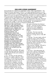
Table 2-2 Toxic and Hazardous Substances and Elements (continued) Part Name Lead (Pb) Mercury (Hg) Cadmium (Cd) Hexavalent Chromium (Cr(VI)) Memory X O O O I/O PCAs X O O O Power supply X O O O Keyboard X O O O Mouse X O O O Chassis/Other X O O O Fans X O O O Internal/External Media Reading X O O O Devices External Control Devices X O O O Cable X O O O Hard Disk Drive X O O O Display X X O O Polybrominated biphenyls (PBB) Polybrominated ...
Table 2-2 Toxic and Hazardous Substances and Elements (continued) Part Name Lead (Pb) Mercury (Hg) Cadmium (Cd) Hexavalent Chromium (Cr(VI)) Memory X O O O I/O PCAs X O O O Power supply X O O O Keyboard X O O O Mouse X O O O Chassis/Other X O O O Fans X O O O Internal/External Media Reading X O O O Devices External Control Devices X O O O Cable X O O O Hard Disk Drive X O O O Display X X O O Polybrominated biphenyls (PBB) Polybrominated ...

Quick Setup & Getting Started Guide
Page 14
... NOTE: If the system does not boot to the CD in the Computer Setup (F10) utility. NOTE: The HP Memory Test is a comprehensive memory diagnostic utility that is optional but recommended after installing or connecting a new device. If you may not be downloaded from... page 7 for more information. Accessing HP Vision Diagnostics (Windows systems) To access HP Vision Diagnostics, you have already downloaded HP Vision Diagnostics to a USB flash drive. 2. Use HP Vision Diagnostics to test memory only. See Downloading the Latest Version of HP Vision Diagnostics. 6 Quick Setup & ...
... NOTE: If the system does not boot to the CD in the Computer Setup (F10) utility. NOTE: The HP Memory Test is a comprehensive memory diagnostic utility that is optional but recommended after installing or connecting a new device. If you may not be downloaded from... page 7 for more information. Accessing HP Vision Diagnostics (Windows systems) To access HP Vision Diagnostics, you have already downloaded HP Vision Diagnostics to a USB flash drive. 2. Use HP Vision Diagnostics to test memory only. See Downloading the Latest Version of HP Vision Diagnostics. 6 Quick Setup & ...

Quick Setup & Getting Started Guide
Page 16
...publications are having problems with U.S., Canadian, and various international regulations. To access the publications, select Start > All Programs > HP User Manuals. NOTE: Not all models. ● Quick Setup & Getting Started-Helps you can reconfigure the power button to...problem before touching. also includes basic troubleshooting information should you are available on all of computers; includes information on RTC batteries, memory, and power supply. ● Maintenance and Service Guide (English only)-Provides information on parts removal and replacement, troubleshooting, Desktop ...
...publications are having problems with U.S., Canadian, and various international regulations. To access the publications, select Start > All Programs > HP User Manuals. NOTE: Not all models. ● Quick Setup & Getting Started-Helps you can reconfigure the power button to...problem before touching. also includes basic troubleshooting information should you are available on all of computers; includes information on RTC batteries, memory, and power supply. ● Maintenance and Service Guide (English only)-Provides information on parts removal and replacement, troubleshooting, Desktop ...

Hardware Reference Guide - Compaq 500B/505B
Page 5
Removing the Front Bezel 1 Press the Power button to turn off the computer. 2 Disconnect all cables and remove all items from the computer. 3 Remove the side cover by loosening the screw that connects the cover to remove it. 5 Remove the side panel by lifting it away from the computer: z Disconnect cables for power, keyboard, mouse, monitor, etc. Slide the cover about 2.4 cm (1 inch) to the computer. z Remove items such as memory cards, USB drives, etc. 4 Grasp the handle on the side cover and pull towards the back of the computer. Removing and Replacing the Front Bezel 5
Removing the Front Bezel 1 Press the Power button to turn off the computer. 2 Disconnect all cables and remove all items from the computer. 3 Remove the side cover by loosening the screw that connects the cover to remove it. 5 Remove the side panel by lifting it away from the computer: z Disconnect cables for power, keyboard, mouse, monitor, etc. Slide the cover about 2.4 cm (1 inch) to the computer. z Remove items such as memory cards, USB drives, etc. 4 Grasp the handle on the side cover and pull towards the back of the computer. Removing and Replacing the Front Bezel 5

Hardware Reference Guide - Compaq 500B/505B
Page 9
Removing and Replacing Memory
Removing and Replacing Memory

Hardware Reference Guide - Compaq 500B/505B
Page 10
...mouse, monitor, etc. WARNING: z Never open the computer, allow the internal system components to the computer. 10 Removing and Replacing Memory z Avoid touching sharp edges inside the computer. z Before you open the cover with the screw seen in the following illustration. z Remove ...items such as memory cards, USB drives, etc. Removing and Replacing Memory 25-30 MINUTES Before You Begin Tools Needed: z Flathead screwdriver z Phillips screwdriver Flathead screwdrivers A flathead screwdriver...
...mouse, monitor, etc. WARNING: z Never open the computer, allow the internal system components to the computer. 10 Removing and Replacing Memory z Avoid touching sharp edges inside the computer. z Before you open the cover with the screw seen in the following illustration. z Remove ...items such as memory cards, USB drives, etc. Removing and Replacing Memory 25-30 MINUTES Before You Begin Tools Needed: z Flathead screwdriver z Phillips screwdriver Flathead screwdrivers A flathead screwdriver...

Hardware Reference Guide - Compaq 500B/505B
Page 11
Removing and Replacing Memory 11 4 Grasp the handle on the side cover and pull towards the back of the memory socket to remove it. 6 Lay the computer on its side. 5 Remove the side panel by lifting it away from the computer. 7 Locate the memory sockets on each end of the computer. Slide the cover about 2.4 cm (1 inch) to release the memory module. 537490-001 - NOTE: The location and number of memory sockets may vary with the motherboard model in your computer. 8 Push down the retaining clip on your computer motherboard.
Removing and Replacing Memory 11 4 Grasp the handle on the side cover and pull towards the back of the memory socket to remove it. 6 Lay the computer on its side. 5 Remove the side panel by lifting it away from the computer. 7 Locate the memory sockets on each end of the computer. Slide the cover about 2.4 cm (1 inch) to release the memory module. 537490-001 - NOTE: The location and number of memory sockets may vary with the motherboard model in your computer. 8 Push down the retaining clip on your computer motherboard.

Hardware Reference Guide - Compaq 500B/505B
Page 12
... original computer specifications. 1 Touching only the top edge of the memory module, locate the notch at the memory module socket for the tab that matches the notch on the memory module. 12 537490-001 - NOTE: Each type of the socket. Removing and Replacing Memory Replacing Memory NOTE: The new (replacement) part may not look exactly...
... original computer specifications. 1 Touching only the top edge of the memory module, locate the notch at the memory module socket for the tab that matches the notch on the memory module. 12 537490-001 - NOTE: Each type of the socket. Removing and Replacing Memory Replacing Memory NOTE: The new (replacement) part may not look exactly...

Hardware Reference Guide - Compaq 500B/505B
Page 13
Removing and Replacing Memory 13 3 Position the memory module over the socket, aligning the notch with the tab in the socket, and then firmly press the module down into the socket. 5 The side panel has several tabs on its top, bottom, and leading edges. ...until the retaining clips at the ends of the socket lock the module into place. 6 The tabs fit into slots and over the front lip of the computer. 4 Set the computer upright. 537490-001 -
Removing and Replacing Memory 13 3 Position the memory module over the socket, aligning the notch with the tab in the socket, and then firmly press the module down into the socket. 5 The side panel has several tabs on its top, bottom, and leading edges. ...until the retaining clips at the ends of the socket lock the module into place. 6 The tabs fit into slots and over the front lip of the computer. 4 Set the computer upright. 537490-001 -

Hardware Reference Guide - Compaq 500B/505B
Page 14
7 To reattach the panel, align the tabs on the panel over the corresponding slots on the computer and all peripherals, such as the keyboard, mouse, Ethernet, and monitor cables. 10 Reconnect the power cord. 11 Turn on the computer. Slide the side cover forward. 8 Reattach the screw at the back of the computer. 9 Connect the cables, such as the monitor. 12 Verify that the replacement memory works properly.
7 To reattach the panel, align the tabs on the panel over the corresponding slots on the computer and all peripherals, such as the keyboard, mouse, Ethernet, and monitor cables. 10 Reconnect the power cord. 11 Turn on the computer. Slide the side cover forward. 8 Reattach the screw at the back of the computer. 9 Connect the cables, such as the monitor. 12 Verify that the replacement memory works properly.

Hardware Reference Guide - Compaq 500B/505B
Page 17
Removing and Replacing an Optical Disc Drive 17 z Remove items such as memory cards, USB drives, etc. 4 Remove the side cover by loosening the screw that connects the cover to turn off the computer. 2 Disconnect all cables and remove all items from the computer: z Disconnect cables for power, keyboard, mouse, monitor, etc. Removing an Optical Disc Drive 1 Press the Power button to the computer. 3 Remove any discs in the drive. 5 Grasp the handle on the side cover and pull towards the back of the computer. Slide the cover about 2.4 cm (1 inch) to remove it.
Removing and Replacing an Optical Disc Drive 17 z Remove items such as memory cards, USB drives, etc. 4 Remove the side cover by loosening the screw that connects the cover to turn off the computer. 2 Disconnect all cables and remove all items from the computer: z Disconnect cables for power, keyboard, mouse, monitor, etc. Removing an Optical Disc Drive 1 Press the Power button to the computer. 3 Remove any discs in the drive. 5 Grasp the handle on the side cover and pull towards the back of the computer. Slide the cover about 2.4 cm (1 inch) to remove it.

Hardware Reference Guide - Compaq 500B/505B
Page 25
Removing and Replacing a Hard Disk Drive 25 Removing a Hard Disk Drive 1 Press the Power button to the computer. z Remove items such as memory cards, USB drives, etc. 4 Grasp the handle on the side cover and pull towards the back of the computer. Slide the cover about 2.4 cm (1 inch) to remove it. 5 Remove the side panel by lifting it away from the computer. 3 Remove the side cover by loosening the screw that connects the cover to turn off the computer. 2 Disconnect all cables and remove all items from the computer: z Disconnect cables for power, keyboard, mouse, monitor, etc.
Removing and Replacing a Hard Disk Drive 25 Removing a Hard Disk Drive 1 Press the Power button to the computer. z Remove items such as memory cards, USB drives, etc. 4 Grasp the handle on the side cover and pull towards the back of the computer. Slide the cover about 2.4 cm (1 inch) to remove it. 5 Remove the side panel by lifting it away from the computer. 3 Remove the side cover by loosening the screw that connects the cover to turn off the computer. 2 Disconnect all cables and remove all items from the computer: z Disconnect cables for power, keyboard, mouse, monitor, etc.

Hardware Reference Guide - Compaq 500B/505B
Page 33
Removing and Replacing an Add-In Card 33 Slide the cover about 2.4 cm (1 inch) to the computer. z Remove items such as memory cards, USB drives, etc. 4 Grasp the handle on the side cover and pull towards the back of the computer. Removing an Add-In Card 1 Press the Power button to turn off the computer. 2 Disconnect all cables and remove all items from the computer. 3 Remove the side cover by loosening the screw that connects the cover to remove it. 5 Remove the side panel by lifting it away from the computer: z Disconnect cables for power, keyboard, mouse, monitor, etc.
Removing and Replacing an Add-In Card 33 Slide the cover about 2.4 cm (1 inch) to the computer. z Remove items such as memory cards, USB drives, etc. 4 Grasp the handle on the side cover and pull towards the back of the computer. Removing an Add-In Card 1 Press the Power button to turn off the computer. 2 Disconnect all cables and remove all items from the computer. 3 Remove the side cover by loosening the screw that connects the cover to remove it. 5 Remove the side panel by lifting it away from the computer: z Disconnect cables for power, keyboard, mouse, monitor, etc.

Hardware Reference Guide - Compaq 500B/505B
Page 41
Removing and Replacing a Power Supply 41 Removing a Power Supply 1 Press the power button to the computer. Slide the cover about 2.4 cm (1 inch) to remove it. 5 Remove the side panel by lifting it away from the computer. 3 Remove the side cover, by loosening the screw that connects the cover to turn off the computer. 2 Disconnect all cables and remove all items from the computer: z Disconnect cables for power, keyboard, mouse, monitor, etc. z Remove items such as memory cards, USB drives, etc. 4 Grasp the handle on the side cover and pull towards the back of the computer.
Removing and Replacing a Power Supply 41 Removing a Power Supply 1 Press the power button to the computer. Slide the cover about 2.4 cm (1 inch) to remove it. 5 Remove the side panel by lifting it away from the computer. 3 Remove the side cover, by loosening the screw that connects the cover to turn off the computer. 2 Disconnect all cables and remove all items from the computer: z Disconnect cables for power, keyboard, mouse, monitor, etc. z Remove items such as memory cards, USB drives, etc. 4 Grasp the handle on the side cover and pull towards the back of the computer.
Maintenance & Service Guide: Compaq 500B and 505B Minitower Business PC
Page 5
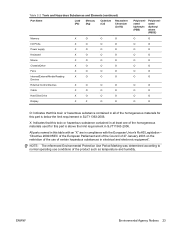
...assembly (AMD) - Model 505B 35 Processor (Intel) - Table of contents 1 Product Description Chassis Designations ...1 Microtower (MT) ...1 Product Description ...2 2 Removal and Replacement Procedures Microtower (MT) Chassis Preparation for Disassembly ...3 Access Panel ...4 Front Bezel ...6 Memory ...8 DDR3-SDRAM DIMMs ...8 Populating DIMM Sockets 9 Installing Memory Modules 10 Expansion Cards ... ...32 System Fan ...33 Heat sink assembly (Intel) - Model 500B ...36 Processor (AMD) - Model 505B ...38 Power Supply ...39 System Board ...45 Battery ...46 Type 1 Battery Holder ...47 v
...assembly (AMD) - Model 505B 35 Processor (Intel) - Table of contents 1 Product Description Chassis Designations ...1 Microtower (MT) ...1 Product Description ...2 2 Removal and Replacement Procedures Microtower (MT) Chassis Preparation for Disassembly ...3 Access Panel ...4 Front Bezel ...6 Memory ...8 DDR3-SDRAM DIMMs ...8 Populating DIMM Sockets 9 Installing Memory Modules 10 Expansion Cards ... ...32 System Fan ...33 Heat sink assembly (Intel) - Model 500B ...36 Processor (AMD) - Model 505B ...38 Power Supply ...39 System Board ...45 Battery ...46 Type 1 Battery Holder ...47 v

Maintenance & Service Guide: Compaq 500B and 505B Minitower Business PC
Page 6
... Setup-Boot ...59 Computer Setup-Exit ...59 Appendix B Diagnostics Interpreting Diagnostic Beep Codes 61 LED Codes ...62 Accessing HP Insight Diagnostics ...63 Testing Memory Modules ...63 POST Error/Warning Messages ...64 Power Button/Power Button LED ...65 Using the Setup Utility ...65 BIOS... Card Reader Problems 73 Solving Display Problems ...74 Solving Audio Problems ...75 Solving Keyboard and Mouse Problems 75 Solving Network Problems ...76 Solving Memory Problems ...77 vi Type 2 Battery Holder ...48 Type 3 Battery Holder ...48 Appendix A Computer (F10) Setup Model 500B - Computer ...
... Setup-Boot ...59 Computer Setup-Exit ...59 Appendix B Diagnostics Interpreting Diagnostic Beep Codes 61 LED Codes ...62 Accessing HP Insight Diagnostics ...63 Testing Memory Modules ...63 POST Error/Warning Messages ...64 Power Button/Power Button LED ...65 Using the Setup Utility ...65 BIOS... Card Reader Problems 73 Solving Display Problems ...74 Solving Audio Problems ...75 Solving Keyboard and Mouse Problems 75 Solving Network Problems ...76 Solving Memory Problems ...77 vi Type 2 Battery Holder ...48 Type 3 Battery Holder ...48 Appendix A Computer (F10) Setup Model 500B - Computer ...

Maintenance & Service Guide: Compaq 500B and 505B Minitower Business PC
Page 16
...operation, the DDR3-SDRAM DIMMs must be populated with up to 4 GB of memory configured in a highperforming dual channel mode. To achieve the maximum memory support, you can be : ● industry-standard 240-pin ● unbuffered...memory (DDR3SDRAM) dual inline memory modules (DIMMs). DDR3-SDRAM DIMMs The memory sockets on the system board can populate the system board with up to two industry-standard DIMMs. These memory sockets are not supported NOTE: The system will not operate properly if you install unsupported DIMMs. 8 Chapter 2 Removal and Replacement Procedures Microtower...
...operation, the DDR3-SDRAM DIMMs must be populated with up to 4 GB of memory configured in a highperforming dual channel mode. To achieve the maximum memory support, you can be : ● industry-standard 240-pin ● unbuffered...memory (DDR3SDRAM) dual inline memory modules (DIMMs). DDR3-SDRAM DIMMs The memory sockets on the system board can populate the system board with up to two industry-standard DIMMs. These memory sockets are not supported NOTE: The system will not operate properly if you install unsupported DIMMs. 8 Chapter 2 Removal and Replacement Procedures Microtower...

Maintenance & Service Guide: Compaq 500B and 505B Minitower Business PC
Page 17
Socket Color Blue Blue Memory 9 Figure 2-6 DIMM Socket Locations - 500B Figure 2-7 DIMM Socket Locations - 505B Table 2-1 DIMM Socket Locations Item Description 1 DIMM1 socket, Channel A (populate first) 2 DIMM2 socket, Channel A NOTE: A DIMM must occupy the DIMM1 socket. Populating DIMM Sockets There are two DIMM sockets on the system board.
Socket Color Blue Blue Memory 9 Figure 2-6 DIMM Socket Locations - 500B Figure 2-7 DIMM Socket Locations - 505B Table 2-1 DIMM Socket Locations Item Description 1 DIMM1 socket, Channel A (populate first) 2 DIMM2 socket, Channel A NOTE: A DIMM must occupy the DIMM1 socket. Populating DIMM Sockets There are two DIMM sockets on the system board.

Maintenance & Service Guide: Compaq 500B and 505B Minitower Business PC
Page 18
... approximately 30 seconds for Disassembly on state, voltage is always supplied to the memory modules as long as the computer is plugged into an active AC outlet. Adding or removing memory modules while voltage is important to use memory modules with gold-plated metal contacts to prevent corrosion and/or oxidation resulting from... electronic components of personal injury from having incompatible metals in contact with each other. Figure 2-8 DIMM locations (500B shown) 10 Chapter 2 Removal and Replacement Procedures Microtower (MT) Chassis Regardless of the power-on page 3). 2.
... approximately 30 seconds for Disassembly on state, voltage is always supplied to the memory modules as long as the computer is plugged into an active AC outlet. Adding or removing memory modules while voltage is important to use memory modules with gold-plated metal contacts to prevent corrosion and/or oxidation resulting from... electronic components of personal injury from having incompatible metals in contact with each other. Figure 2-8 DIMM locations (500B shown) 10 Chapter 2 Removal and Replacement Procedures Microtower (MT) Chassis Regardless of the power-on page 3). 2.


