
Service Manual
Page 9
......123 Replacing the ADF pickup-roller assembly 124 Removing the ADF separation pad 130 Replacing the ADF scanner glass 132 Replacing the fuser assembly 133 Replacing the control-panel bezel ... the memory-card assembly (HP Color LaserJet 2840 all-in-one only 157 Removing the input/output (I/O) cover 158 Removing the back cover 161 Removing the top cover assembly 162 Removing the... cover 169 Main assemblies...1. 72 Removing the control panel 172 Removing the left support assembly 173 Removing the right support assembly 174 Removing the laser/scanner assembly 175 Removing the ...
......123 Replacing the ADF pickup-roller assembly 124 Removing the ADF separation pad 130 Replacing the ADF scanner glass 132 Replacing the fuser assembly 133 Replacing the control-panel bezel ... the memory-card assembly (HP Color LaserJet 2840 all-in-one only 157 Removing the input/output (I/O) cover 158 Removing the back cover 161 Removing the top cover assembly 162 Removing the... cover 169 Main assemblies...1. 72 Removing the control panel 172 Removing the left support assembly 173 Removing the right support assembly 174 Removing the laser/scanner assembly 175 Removing the ...
Service Manual
Page 74
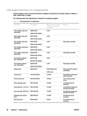
...Q3963-67902 (EMEA) Q3964-67901 Transfer roller RF5-4067-000CN Device pickup roller RB3-0160-000CN Device separation pad RF5-4012-000 Fuser assembly, 110-127 V) RG5-7602-000 Fuser assembly, 220-240 V) RG5-7603-000 Separation pad, optional tray 2 ADF pickup roller RB2-9960-000 Q3948-67903 Estimated life (...) 5,000 Remarks 2,000 4,000 High-capacity cartridge 2,000 4,000 High-capacity cartridge 2,000 4,000 High-capacity cartridge 20,000 (black only) 5,000 (color) 100,000 100,000 100,000 100,000 100,000 100,000 50,000 The average life is 6,000 to 8,000 pages. Can affect print...
...Q3963-67902 (EMEA) Q3964-67901 Transfer roller RF5-4067-000CN Device pickup roller RB3-0160-000CN Device separation pad RF5-4012-000 Fuser assembly, 110-127 V) RG5-7602-000 Fuser assembly, 220-240 V) RG5-7603-000 Separation pad, optional tray 2 ADF pickup roller RB2-9960-000 Q3948-67903 Estimated life (...) 5,000 Remarks 2,000 4,000 High-capacity cartridge 2,000 4,000 High-capacity cartridge 2,000 4,000 High-capacity cartridge 20,000 (black only) 5,000 (color) 100,000 100,000 100,000 100,000 100,000 100,000 50,000 The average life is 6,000 to 8,000 pages. Can affect print...
Service Manual
Page 131
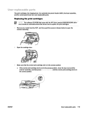
...The software CD-ROM that came with the HP Color LaserJet 2820/2830/2840 all-inone includes an animated tutorial that shows how to replace the print cartridges. 1 Remove any media from the ADF, and then push the scanner-release button to open the scanner assembly. 2 Open the cartridge door. 3 Make..., close the top cover and the scanner assembly, and then press ROTATE CAROUSEL until the correct print-cartridge slot is in the correct position. User-replaceable parts The print cartridges, the imaging drum, the automatic document feeder (ADF), the fuser assembly , and the control-panel bezel are user...
...The software CD-ROM that came with the HP Color LaserJet 2820/2830/2840 all-inone includes an animated tutorial that shows how to replace the print cartridges. 1 Remove any media from the ADF, and then push the scanner-release button to open the scanner assembly. 2 Open the cartridge door. 3 Make..., close the top cover and the scanner assembly, and then press ROTATE CAROUSEL until the correct print-cartridge slot is in the correct position. User-replaceable parts The print cartridges, the imaging drum, the automatic document feeder (ADF), the fuser assembly , and the control-panel bezel are user...

Service Manual
Page 145
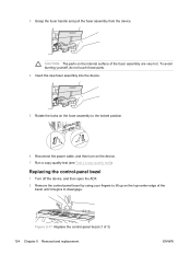
... fingerprints can contaminate the glass or pad and cause print-quality problems or paperpickup problems. 3 Replace the torx screw to the unlocked position. Replacing the fuser assembly 1 Turn off the device, and then disconnect the power cable. 2 Rotate the locks on the frame and glass until the lock mechanism snaps back into... the locked position, as shown in the released position. ENWW User-replaceable parts 133 Press down on the fuser assembly to secure the glass. Make sure the lock mechanism is in Figure 5-16 Install the ADF scanner glass.
... fingerprints can contaminate the glass or pad and cause print-quality problems or paperpickup problems. 3 Replace the torx screw to the unlocked position. Replacing the fuser assembly 1 Turn off the device, and then disconnect the power cable. 2 Rotate the locks on the frame and glass until the lock mechanism snaps back into... the locked position, as shown in the released position. ENWW User-replaceable parts 133 Press down on the fuser assembly to secure the glass. Make sure the lock mechanism is in Figure 5-16 Install the ADF scanner glass.
Service Manual
Page 146
To avoid burning yourself, do not touch those parts. 4 Insert the new fuser assembly into the device. 5 Rotate the locks on the fuser assembly to the locked position. 6 Reconnect the power cable, and then turn on the top-center edge of the bezel until it begins to lift up ..., and then open the ADF. 2 Remove the control-panel bezel by using your fingers to disengage. Figure 5-17 Replace the control-panel bezel (1 of the fuser assembly are very hot. CAUTION The parts on the internal surface of 3) 134 Chapter 5 Removal and replacement ENWW 3 Grasp the...
To avoid burning yourself, do not touch those parts. 4 Insert the new fuser assembly into the device. 5 Rotate the locks on the fuser assembly to the locked position. 6 Reconnect the power cable, and then turn on the top-center edge of the bezel until it begins to lift up ..., and then open the ADF. 2 Remove the control-panel bezel by using your fingers to disengage. Figure 5-17 Replace the control-panel bezel (1 of the fuser assembly are very hot. CAUTION The parts on the internal surface of 3) 134 Chapter 5 Removal and replacement ENWW 3 Grasp the...
Service Manual
Page 171
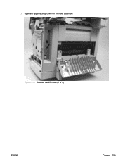
2 Open the upper face-up cover on the fuser assembly. Figure 5-37 Remove the I/O cover (1 of 3) ENWW Covers 159
2 Open the upper face-up cover on the fuser assembly. Figure 5-37 Remove the I/O cover (1 of 3) ENWW Covers 159

Service Manual
Page 173
4 Pull the top of the cover. ENWW Covers 161 Figure 5-39 Remove the I/O cover (3 of 3) Removing the back cover 1 Remove the following covers ● Left cover (see Removing the left cover) ● Right cover (see Removing the right cover) ● Left rear cover (see Removing the left rear cover) ● Right rear cover (see Removing the right rear cover) ● I/O cover (see Removing the input/output (I /O cover away from the device to disengage the latches (callout 2) at the bottom of the I /O) cover) Leave the upper face-up cover on the fuser assembly open.
4 Pull the top of the cover. ENWW Covers 161 Figure 5-39 Remove the I/O cover (3 of 3) Removing the back cover 1 Remove the following covers ● Left cover (see Removing the left cover) ● Right cover (see Removing the right cover) ● Left rear cover (see Removing the left rear cover) ● Right rear cover (see Removing the right rear cover) ● I/O cover (see Removing the input/output (I /O cover away from the device to disengage the latches (callout 2) at the bottom of the I /O) cover) Leave the upper face-up cover on the fuser assembly open.
Service Manual
Page 211
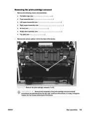
... Removing the print-cartridge carousel 1 Remove the following covers and assemblies: ● Formatter cage (see Removing the formatter cage) ● Fuser assembly (see Replacing the fuser assembly) ● Left support assembly (see Removing the left support assembly) ● Right support assembly (see Removing the right support assembly) ● Air duct (see Removing the air duct and fan) ● Rotary...
... Removing the print-cartridge carousel 1 Remove the following covers and assemblies: ● Formatter cage (see Removing the formatter cage) ● Fuser assembly (see Replacing the fuser assembly) ● Left support assembly (see Removing the left support assembly) ● Right support assembly (see Removing the right support assembly) ● Air duct (see Removing the air duct and fan) ● Rotary...
Service Manual
Page 217
...out loose toner from inside the device, and then turn it rests on the scanning assembly in step 2. 3 Release the tab on which the overturned device will rest. ENWW Main assemblies 205 Hewlett-Packard recommends that two people lift the device and turn the device over... the right rear cover) ● I/O cover (see Removing the input/output (I/O) cover) ● ADF (see Replacing the ADF) ● Fuser assembly (see Replacing the fuser assembly) ● Toner-catch tray (see Removing the toner-catch tray) ● Transfer-roller plate (see Removing the transfer-roller plate) ●...
...out loose toner from inside the device, and then turn it rests on the scanning assembly in step 2. 3 Release the tab on which the overturned device will rest. ENWW Main assemblies 205 Hewlett-Packard recommends that two people lift the device and turn the device over... the right rear cover) ● I/O cover (see Removing the input/output (I/O) cover) ● ADF (see Replacing the ADF) ● Fuser assembly (see Replacing the fuser assembly) ● Toner-catch tray (see Removing the toner-catch tray) ● Transfer-roller plate (see Removing the transfer-roller plate) ●...

Service Manual
Page 226
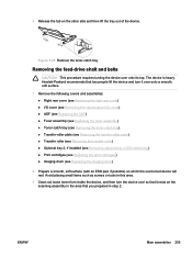
... power supply cover plate CAUTION This procedure requires turning the device over onto a smooth, soft surface. 1 Remove the following covers and assemblies: ● ADF (see Replacing the ADF) ● Left cover (see Removing the left cover) ● Right cover (see ...cover (see Removing the input/output (I/O) cover) ● Back cover (see Removing the back cover) ● Fuser assembly (see Replacing the fuser assembly) ● Top cover assembly (see Removing the top cover assembly) ● Formatter cage (see Removing the formatter cage) ● Optional tray 2 (see Removing optional tray 2...
... power supply cover plate CAUTION This procedure requires turning the device over onto a smooth, soft surface. 1 Remove the following covers and assemblies: ● ADF (see Replacing the ADF) ● Left cover (see Removing the left cover) ● Right cover (see ...cover (see Removing the input/output (I/O) cover) ● Back cover (see Removing the back cover) ● Fuser assembly (see Replacing the fuser assembly) ● Top cover assembly (see Removing the top cover assembly) ● Formatter cage (see Removing the formatter cage) ● Optional tray 2 (see Removing optional tray 2...
Service Manual
Page 230
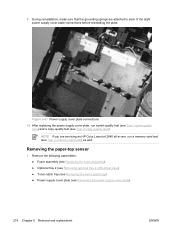
Removing the paper-top sensor 1 Remove the following assemblies: ● Fuser assembly (see Replacing the fuser assembly) ● Optional tray 2 (see Removing optional tray 2 (250-sheet tray)) ● Toner-catch tray (see Removing the toner-catch tray) ● ... each of the eight power supply cover plate connections before reinstalling the plate. 9 During reinstallation, make sure that the grounding springs are servicing an HP Color LaserJet 2840 all-in-one, run a print-quality test (see Test 1 (print-quality test)) and a copy-quality test (see Test 2 (copy-quality test)). Figure ...
Removing the paper-top sensor 1 Remove the following assemblies: ● Fuser assembly (see Replacing the fuser assembly) ● Optional tray 2 (see Removing optional tray 2 (250-sheet tray)) ● Toner-catch tray (see Removing the toner-catch tray) ● ... each of the eight power supply cover plate connections before reinstalling the plate. 9 During reinstallation, make sure that the grounding springs are servicing an HP Color LaserJet 2840 all-in-one, run a print-quality test (see Test 1 (print-quality test)) and a copy-quality test (see Test 2 (copy-quality test)). Figure ...
Service Manual
Page 265
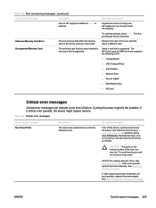
... error persists, replace the power supply. To continue printing, press ENTER. If the error persists, replace the fuser assembly. See Removing the power supply cover plate. The HP Color LaserJet 2840 all-in-one supports the following cards: ■ CompactFlash ■ Ultra CompactFlash ■ Smart Media ■ Memory Stick ■ Secure Digital ■ Multi Media Card...
... error persists, replace the power supply. To continue printing, press ENTER. If the error persists, replace the fuser assembly. See Removing the power supply cover plate. The HP Color LaserJet 2840 all-in-one supports the following cards: ■ CompactFlash ■ Ultra CompactFlash ■ Smart Media ■ Memory Stick ■ Secure Digital ■ Multi Media Card...
Service Manual
Page 271
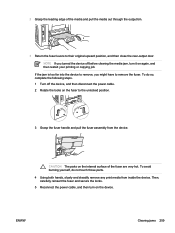
...restart your printing or copying job. NOTE If you might have to the unlocked position. 3 Grasp the fuser handle and pull the fuser assembly from inside the device. Then, carefully reinsert the fuser and secure the locks. 5 Reconnect the power cable, and then turn it on the internal surface of ...the media and pull the media out through the output bin. 3 Return the fuser levers to their original ...
...restart your printing or copying job. NOTE If you might have to the unlocked position. 3 Grasp the fuser handle and pull the fuser assembly from inside the device. Then, carefully reinsert the fuser and secure the locks. 5 Reconnect the power cable, and then turn it on the internal surface of ...the media and pull the media out through the output bin. 3 Return the fuser levers to their original ...
Service Manual
Page 280
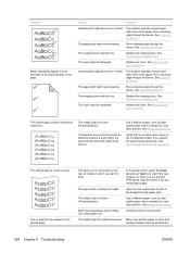
... skewed on them . The media might not meet HP specifications. See Replacing the imaging drum. See Media specifications. Verify that the problem also occurs on which you are incorrectly formed so that is intended for color laser printers. In the printer driver, select the Paper... tab and set to print. The paper path might be low. Run a cleaning page through the device. See Replacing the fuser assembly. The problem typically corrects itself after a few...
... skewed on them . The media might not meet HP specifications. See Replacing the imaging drum. See Media specifications. Verify that the problem also occurs on which you are incorrectly formed so that is intended for color laser printers. In the printer driver, select the Paper... tab and set to print. The paper path might be low. Run a cleaning page through the device. See Replacing the fuser assembly. The problem typically corrects itself after a few...
Service Manual
Page 308
...you removed the entire length of the sealing tape from the print cartridge before you to view the drum surface. See Replacing the fuser assembly. 296 Chapter 6 Troubleshooting ENWW The leading edge of the image-formation process (see the list at least ten minutes, and then remove the... fuser. Troubleshoot the failure as a transfer or fusing problem. See Engine test. 2 During the engine test, open the cartridge door after the motor begins...
...you removed the entire length of the sealing tape from the print cartridge before you to view the drum surface. See Replacing the fuser assembly. 296 Chapter 6 Troubleshooting ENWW The leading edge of the image-formation process (see the list at least ten minutes, and then remove the... fuser. Troubleshoot the failure as a transfer or fusing problem. See Engine test. 2 During the engine test, open the cartridge door after the motor begins...
Service Manual
Page 388
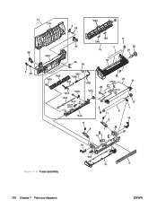
Figure 7-14 Fuser assembly 376 Chapter 7 Parts and diagrams ENWW
Figure 7-14 Fuser assembly 376 Chapter 7 Parts and diagrams ENWW

Service Manual
Page 389
Table 7-17 Fuser assembly Ref Description Fuser assembly, 110-127V Fuser assembly, 220-240V 1 Bushing 2 Bushing 3 Lever, lock release, right 4 Lever, lock release, left 5 Guide, paper inlet 6 Pressure plate 7 High-temperature caution label 8 Roller, pressure 9 Screw, RS, M3x8 10 Base plate, fixing 11 Spring, compression 12 Gear, 30T 13 Clamp, cable 14 Fuser film assembly 14 Fuser film assembly 15 Separation...
Table 7-17 Fuser assembly Ref Description Fuser assembly, 110-127V Fuser assembly, 220-240V 1 Bushing 2 Bushing 3 Lever, lock release, right 4 Lever, lock release, left 5 Guide, paper inlet 6 Pressure plate 7 High-temperature caution label 8 Roller, pressure 9 Screw, RS, M3x8 10 Base plate, fixing 11 Spring, compression 12 Gear, 30T 13 Clamp, cable 14 Fuser film assembly 14 Fuser film assembly 15 Separation...

Service Manual
Page 394
... assembly ADF and scanner assembly ADF and scanner assembly ADF and scanner assembly ADF and scanner assembly ADF and scanner assembly ADF and scanner assembly Covers Internal components (2 of 2) Rotary assembly Fuser assembly Front frame assembly Front frame assembly Internal components (1 of 2) Rear frame assembly Middle frame assembly Middle frame assembly Middle frame assembly Middle frame assembly Fuser assembly Fuser assembly Fuser assembly Rotary assembly Rotary assembly Main drive assembly Main drive assembly Front frame assembly Front frame assembly...
... assembly ADF and scanner assembly ADF and scanner assembly ADF and scanner assembly ADF and scanner assembly ADF and scanner assembly ADF and scanner assembly Covers Internal components (2 of 2) Rotary assembly Fuser assembly Front frame assembly Front frame assembly Internal components (1 of 2) Rear frame assembly Middle frame assembly Middle frame assembly Middle frame assembly Middle frame assembly Fuser assembly Fuser assembly Fuser assembly Rotary assembly Rotary assembly Main drive assembly Main drive assembly Front frame assembly Front frame assembly...
Service Manual
Page 395
... base assembly Middle frame assembly Middle frame assembly Power-supply base assembly Middle frame assembly Internal components (2 of 2) Power-supply base assembly Power-supply base assembly Main drive assembly Internal components (2 of 2) Power-supply base assembly Internal components (1 of 2) Power-supply base assembly Front frame assembly Front frame assembly Front frame assembly Rotary assembly Front frame assembly Rotary assembly Rotary assembly Rotary assembly Front frame assembly Middle frame assembly Fuser assembly Alphabetical...
... base assembly Middle frame assembly Middle frame assembly Power-supply base assembly Middle frame assembly Internal components (2 of 2) Power-supply base assembly Power-supply base assembly Main drive assembly Internal components (2 of 2) Power-supply base assembly Internal components (1 of 2) Power-supply base assembly Front frame assembly Front frame assembly Front frame assembly Rotary assembly Front frame assembly Rotary assembly Rotary assembly Rotary assembly Front frame assembly Middle frame assembly Fuser assembly Alphabetical...
Service Manual
Page 397
... and scanner assembly ADF and scanner assembly ADF and scanner assembly ADF and scanner assembly ADF and scanner assembly ADF and scanner assembly ADF and scanner assembly ADF and scanner assembly ADF and scanner assembly ADF and scanner assembly ADF and scanner assembly ADF and scanner assembly Main drive assembly Main drive assembly Covers Covers Internal components (2 of 2) Covers Fuser assembly Fuser assembly Covers Fuser assembly Middle frame assembly Covers Alphabetical...
... and scanner assembly ADF and scanner assembly ADF and scanner assembly ADF and scanner assembly ADF and scanner assembly ADF and scanner assembly ADF and scanner assembly ADF and scanner assembly ADF and scanner assembly ADF and scanner assembly ADF and scanner assembly ADF and scanner assembly Main drive assembly Main drive assembly Covers Covers Internal components (2 of 2) Covers Fuser assembly Fuser assembly Covers Fuser assembly Middle frame assembly Covers Alphabetical...


