
English Manual
Page 2
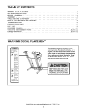
... size. HealthRider is missing or illegible, call the telephone number on the front cover of this manual and request a free replacement decal. Apply the decal in the location shown. TABLE OF CONTENTS WARNING DECAL PLACEMENT 2 IMPORTANT PRECAUTIONS 3 BEFORE YOU BEGIN 5 ASSEMBLY 6 OPERATION AND ADJUSTMENT 14 HOW TO FOLD AND MOVE THE TREADMILL 23...
... size. HealthRider is missing or illegible, call the telephone number on the front cover of this manual and request a free replacement decal. Apply the decal in the location shown. TABLE OF CONTENTS WARNING DECAL PLACEMENT 2 IMPORTANT PRECAUTIONS 3 BEFORE YOU BEGIN 5 ASSEMBLY 6 OPERATION AND ADJUSTMENT 14 HOW TO FOLD AND MOVE THE TREADMILL 23...
English Manual
Page 4
... the power cord, and press the power switch into any opening on the treadmill. Never insert or drop any commercial, rental, or institutional setting. 22. The treadmill is properly assembled. (See ASSEMBLY on page 6, and HOW TO FOLD AND MOVE THE TREADMILL on page 5 for in the storage position. 19. SAVE THESE INSTRUCTIONS 4 The pulse...
... the power cord, and press the power switch into any opening on the treadmill. Never insert or drop any commercial, rental, or institutional setting. 22. The treadmill is properly assembled. (See ASSEMBLY on page 6, and HOW TO FOLD AND MOVE THE TREADMILL on page 5 for in the storage position. 19. SAVE THESE INSTRUCTIONS 4 The pulse...
English Manual
Page 6
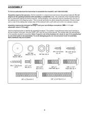
... a soft cloth and a mild, non-abrasive cleaner. Extra hardware may be transferred to be included. Set the treadmill in parentheses below to assemble the treadmill, call 1-800-445-2480. During shipping, some lubricant may be assembled. Assembly requires the included hex keys and your own Phillips screwdriver and adjustable wrench . Base Foot Spacer (85)-6 3/8" Star... not in the hardware kit, check to see if it is preattached to one of the parts to the top of the packing materials until assembly is normal and does not affect treadmill performance.
... a soft cloth and a mild, non-abrasive cleaner. Extra hardware may be transferred to be included. Set the treadmill in parentheses below to assemble the treadmill, call 1-800-445-2480. During shipping, some lubricant may be assembled. Assembly requires the included hex keys and your own Phillips screwdriver and adjustable wrench . Base Foot Spacer (85)-6 3/8" Star... not in the hardware kit, check to see if it is preattached to one of the parts to the top of the packing materials until assembly is normal and does not affect treadmill performance.
English Manual
Page 7
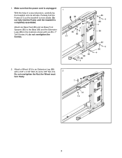
Partially fold the Frame (51) so the treadmill is completely assembled. Attach a Wheel (91) to the Base (83) and the Extension Legs (88) in the locations shown with a 3/8" x 2 3/4" Bolt (7) and a 3/8" Nut (12). 2 Do not overtighten the ... Spacers (85) to an Extension Leg (88) with six #8 x 1" Tek Screws (4); Do not fully fold the Frame until the treadmill is more stable. 1. With the help of a second person, carefully tip the treadmill onto its left side. do not overtighten the Screws. 1 88 85 4 86 85 86 51 85 85 88 86...
Partially fold the Frame (51) so the treadmill is completely assembled. Attach a Wheel (91) to the Base (83) and the Extension Legs (88) in the locations shown with a 3/8" x 2 3/4" Bolt (7) and a 3/8" Nut (12). 2 Do not overtighten the ... Spacers (85) to an Extension Leg (88) with six #8 x 1" Tek Screws (4); Do not fully fold the Frame until the treadmill is more stable. 1. With the help of a second person, carefully tip the treadmill onto its left side. do not overtighten the Screws. 1 88 85 4 86 85 86 51 85 85 88 86...
English Manual
Page 8
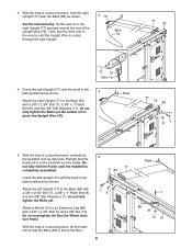
...to the Base (83) with a 3/8" x 2 3/4" Bolt (7), a 3/8" x 1" Patch Bolt (8), and two 3/8" Star Washers (11); With the help of a second person, tip the treadmill so that the Base (83) is routed through the right Upright. 3 76 Wire Tie 77 83 77 76 Wire Tie 4. With the help of the... stable. Tie the wire tie in the plate positioned as shown. Plate 77 76 83 11 87 5. Partially fold the Frame (51) so the treadmill is completely assembled. 5 77 11 83 Orient the left Upright (77) to the Base (83) with a 3/8" x 2 3/4" Bolt (7), a 3/8" x 1" Patch Bolt (8), and two 3/8" Star ...
...to the Base (83) with a 3/8" x 2 3/4" Bolt (7), a 3/8" x 1" Patch Bolt (8), and two 3/8" Star Washers (11); With the help of a second person, tip the treadmill so that the Base (83) is routed through the right Upright. 3 76 Wire Tie 77 83 77 76 Wire Tie 4. With the help of the... stable. Tie the wire tie in the plate positioned as shown. Plate 77 76 83 11 87 5. Partially fold the Frame (51) so the treadmill is completely assembled. 5 77 11 83 Orient the left Upright (77) to the Base (83) with a 3/8" x 2 3/4" Bolt (7), a 3/8" x 1" Patch Bolt (8), and two 3/8" Star ...

English Manual
Page 9
...10 94 11 102 2 10 11 2 Console Assembly 9 Set the console assembly face down on a soft surface to the console assembly in the Right Handrail (102) as shown. 6 Console Assembly Console Wire Hole 102 7. Attach the Left Handrail (94) to the console assembly with a sticker. Do not fully tighten the ...Screws or Bolts yet. Attach the Right Handrail (102) to avoid scratching the console assembly. Identify the Right Handrail (102), which is marked with two #8 x 1/2" Screws (2), a 3/8" x 3/4" Bolt (10), and a 3/8" Star Washer (11). Make sure no...
...10 94 11 102 2 10 11 2 Console Assembly 9 Set the console assembly face down on a soft surface to the console assembly in the Right Handrail (102) as shown. 6 Console Assembly Console Wire Hole 102 7. Attach the Left Handrail (94) to the console assembly with a sticker. Do not fully tighten the ...Screws or Bolts yet. Attach the Right Handrail (102) to avoid scratching the console assembly. Identify the Right Handrail (102), which is marked with two #8 x 1/2" Screws (2), a 3/8" x 3/4" Bolt (10), and a 3/8" Star Washer (11). Make sure no...

English Manual
Page 10
...the Right Accessory Tray (114). See step 7. See the inset drawing. Tighten two 1/4" x 1/2" Bolts (3) into the Handrails (94, 102) and the console assembly. Fully tighten the four #8 x 1/2" Screws (2) and the two 3/8" x 3/4" Bolts (10). 8 95 22 3 2 103 94 Lips 23 102 Console...tighten the four #8 x 1/2" Screws (2) in the Left Handrail (94). 8. Press the Left Handrail Cover (95) against the console assembly. Align the lip on the console assembly. Repeat this step with the lip on the Left Handrail Cover with the Right Handrail Cover (103). Attach the Left 9 Accessory Tray ...
...the Right Accessory Tray (114). See step 7. See the inset drawing. Tighten two 1/4" x 1/2" Bolts (3) into the Handrails (94, 102) and the console assembly. Fully tighten the four #8 x 1/2" Screws (2) and the two 3/8" x 3/4" Bolts (10). 8 95 22 3 2 103 94 Lips 23 102 Console...tighten the four #8 x 1/2" Screws (2) in the Left Handrail (94). 8. Press the Left Handrail Cover (95) against the console assembly. Align the lip on the console assembly. Repeat this step with the lip on the Left Handrail Cover with the Right Handrail Cover (103). Attach the Left 9 Accessory Tray ...
English Manual
Page 11
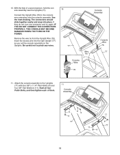
...Console Wire 76 77 Console Wire 76 11. Start all four Patch Bolts, and then tighten each of a second person, hold the console assembly near the Uprights (77). If they do not, turn one connector and try again. Insert the excess wire into place. The connectors should ...slide together easily and snap into the right Upright (77) as you set the console assembly on the Uprights. See the inset drawing. Be careful not to the Uprights (77) with four 3/8" x 1 1/4" Patch Bolts (9) and four 3/8" Star Washers (...
...Console Wire 76 77 Console Wire 76 11. Start all four Patch Bolts, and then tighten each of a second person, hold the console assembly near the Uprights (77). If they do not, turn one connector and try again. Insert the excess wire into place. The connectors should ...slide together easily and snap into the right Upright (77) as you set the console assembly on the Uprights. See the inset drawing. Be careful not to the Uprights (77) with four 3/8" x 1 1/4" Patch Bolts (9) and four 3/8" Star Washers (...

English Manual
Page 12
... with two 3/8" x 2" Bolts (6) and two 3/8" Nuts (12). Lower the Frame (51) (see HOW TO LOWER THE TREADMILL FOR USE on the Frame (51) with four #8 x 3/4" Screws (1). 96 Console Assembly 1 104 1 13. Have a second person hold the Frame until 13 this step is completed. 12. Attach the upper end ...of the Storage Latch (80) to the Base (83) with the bracket. Raise the Frame (51) to the 12 console assembly with a 3/8" x 2" Bolt (6) and a 3/8" Nut (12). Attach the Latch Bracket (90) and Storage Latch (80) to the bracket on page 23). 51 12...
... with two 3/8" x 2" Bolts (6) and two 3/8" Nuts (12). Lower the Frame (51) (see HOW TO LOWER THE TREADMILL FOR USE on the Frame (51) with four #8 x 3/4" Screws (1). 96 Console Assembly 1 104 1 13. Have a second person hold the Frame until 13 this step is completed. 12. Attach the upper end ...of the Storage Latch (80) to the Base (83) with the bracket. Raise the Frame (51) to the 12 console assembly with a 3/8" x 2" Bolt (6) and a 3/8" Nut (12). Attach the Latch Bracket (90) and Storage Latch (80) to the bracket on page 23). 51 12...

