
English Manual
Page 3
... put the treadmill in speed. 19. Never move the walking belt while the power is not working properly.) 8. Do not operate the treadmill if the power cord or plug is damaged, or if the treadmill is not working properly. (See TROUBLESHOOTING on page 22 if the treadmill is turned off. Never use an extension cord. 12. Always hold the handrails while using the treadmill. The pulse sensor is being administered. 7. ICON assumes no...
... put the treadmill in speed. 19. Never move the walking belt while the power is not working properly.) 8. Do not operate the treadmill if the power cord or plug is damaged, or if the treadmill is not working properly. (See TROUBLESHOOTING on page 22 if the treadmill is turned off. Never use an extension cord. 12. Always hold the handrails while using the treadmill. The pulse sensor is being administered. 7. ICON assumes no...
English Manual
Page 4
... or death. Do not attempt to raise, lower, or move the treadmill. 22. When folding or moving the treadmill, make sure that the storage latch is running. nance and adjustment procedures described in this treadmill in -home use , before cleaning the treadmill, and before performing the mainte- SAVE THESE INSTRUCTIONS 4 Always remove the key, unplug the power cord, and press the power switch into any object into the off position when...
... or death. Do not attempt to raise, lower, or move the treadmill. 22. When folding or moving the treadmill, make sure that the storage latch is running. nance and adjustment procedures described in this treadmill in -home use , before cleaning the treadmill, and before performing the mainte- SAVE THESE INSTRUCTIONS 4 Always remove the key, unplug the power cord, and press the power switch into any object into the off position when...
English Manual
Page 5
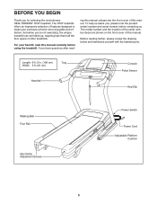
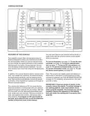
... manual. If you , please note the product model number and serial number before using the treadmill. Before reading further, please review the drawing below and familiarize yourself with the labeled parts. And when you for selecting the revolutionary HEALTHRIDER® H79T treadmill. Length: 6 ft. 5 in. (196 cm) Width: 3 ft. (91 cm) Tray Handrail Console Pulse Sensor Key/Clip Walking Belt Foot Rail Idler Roller Adjustment Screws Power Switch Power Cord Adjustable Platform Cushion 5 For your workouts at home...
... manual. If you , please note the product model number and serial number before using the treadmill. Before reading further, please review the drawing below and familiarize yourself with the labeled parts. And when you for selecting the revolutionary HEALTHRIDER® H79T treadmill. Length: 6 ft. 5 in. (196 cm) Width: 3 ft. (91 cm) Tray Handrail Console Pulse Sensor Key/Clip Walking Belt Foot Rail Idler Roller Adjustment Screws Power Switch Power Cord Adjustable Platform Cushion 5 For your workouts at home...
English Manual
Page 6
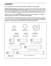
... treadmill, call 1-800-445-2480. Set the treadmill in parentheses below to identify the assembly hardware. Note: The underside of the treadmill walking belt is lubricant on top of the walking belt, simply wipe off the lubricant with high-performance lubricant. The number in a cleared area and remove all packing materials. Extra hardware may have been preassembled. This is the key number of the part, from the PART LIST...
... treadmill, call 1-800-445-2480. Set the treadmill in parentheses below to identify the assembly hardware. Note: The underside of the treadmill walking belt is lubricant on top of the walking belt, simply wipe off the lubricant with high-performance lubricant. The number in a cleared area and remove all packing materials. Extra hardware may have been preassembled. This is the key number of the part, from the PART LIST...

English Manual
Page 9
... 9 6. Attach the pulse bar assembly to the Pulse Bar Bottom (87) with seven #8 x 1/2" Screws (1). do not fully tighten the Patch Bolts yet. Be 1 careful not to the Pulse Bar Bottom 6 (87) with four 3/8" x 4 1/2" Patch Bolts (5) and four 3/8" Star Washers (13); Attach the Handrails to pinch the pulse wire. Identify the Left and Right Handrails (81, 82). Insert the pulse wire from the Upright Wire (77). Start all four Patch Bolts, and...
... 9 6. Attach the pulse bar assembly to the Pulse Bar Bottom (87) with seven #8 x 1/2" Screws (1). do not fully tighten the Patch Bolts yet. Be 1 careful not to the Pulse Bar Bottom 6 (87) with four 3/8" x 4 1/2" Patch Bolts (5) and four 3/8" Star Washers (13); Attach the Handrails to pinch the pulse wire. Identify the Left and Right Handrails (81, 82). Insert the pulse wire from the Upright Wire (77). Start all four Patch Bolts, and...
English Manual
Page 10
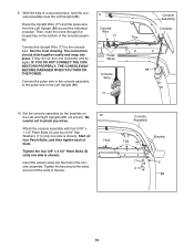
... NOT CONNECT THE CONNECTORS PROPERLY, THE CONSOLE MAY BECOME DAMAGED WHEN YOU TURN ON THE POWER. Be careful not to the pulse wire in the Left Upright (88). 9 Console Wire 77 Pulse Wires Console Wire 77 Console Assembly Crossbar Ties 88 10. Start all four Patch Bolts, and then tighten each of a second person, hold the console assembly near the Left Upright (88). With the help of them. Then, route the wires through...
... NOT CONNECT THE CONNECTORS PROPERLY, THE CONSOLE MAY BECOME DAMAGED WHEN YOU TURN ON THE POWER. Be careful not to the pulse wire in the Left Upright (88). 9 Console Wire 77 Pulse Wires Console Wire 77 Console Assembly Crossbar Ties 88 10. Start all four Patch Bolts, and then tighten each of a second person, hold the console assembly near the Left Upright (88). With the help of them. Then, route the wires through...
English Manual
Page 13
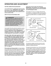
... voltage changes in - Contact a qualified electrician to the walking belt or the walking platform. The surge suppressor must be compatible with your 2 treadmill, always use a properly functioning surge suppressor could damage the control system of damaging your treadmill (see precaution 13 on page 3. This productʼs power cord has an equipment-grounding conductor and a grounding plug. Some 2-pole receptacle outlet box covers...
... voltage changes in - Contact a qualified electrician to the walking belt or the walking platform. The surge suppressor must be compatible with your 2 treadmill, always use a properly functioning surge suppressor could damage the control system of damaging your treadmill (see precaution 13 on page 3. This productʼs power cord has an equipment-grounding conductor and a grounding plug. Some 2-pole receptacle outlet box covers...
English Manual
Page 14
... using the handgrip pulse sensor. You can change the speed and incline of the treadmill with your heart rate using the treadmill. To turn on the power, see THE INFORMATION MODE on page 19. To purchase an iFit Live module at any time, go to www.iFit.com or call the telephone number on the console, remove the plastic. When you use the treadmill, observe the alignment of the walking belt, and center the walking belt...
... using the handgrip pulse sensor. You can change the speed and incline of the treadmill with your heart rate using the treadmill. To turn on the power, see THE INFORMATION MODE on page 19. To purchase an iFit Live module at any time, go to www.iFit.com or call the telephone number on the console, remove the plastic. When you use the treadmill, observe the alignment of the walking belt, and center the walking belt...
English Manual
Page 15
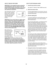
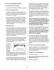
... the numbered Quick Incline buttons. Start the walking belt. If you press one of the buttons, the treadmill will gradually change speed until it reaches the selected speed setting. To restart the walking belt, press the Start button or the Speed increase button. 4. Each time you press one of the numbered Quick Speed buttons, the walking belt will gradually adjust to the selected incline setting. 15 See HOW TO TURN ON THE POWER at - Next, locate the power switch on the power. Reset IMPORTANT: The console features a display demo mode...
... the numbered Quick Incline buttons. Start the walking belt. If you press one of the buttons, the treadmill will gradually change speed until it reaches the selected speed setting. To restart the walking belt, press the Start button or the Speed increase button. 4. Each time you press one of the numbered Quick Speed buttons, the walking belt will gradually adjust to the selected incline setting. 15 See HOW TO TURN ON THE POWER at - Next, locate the power switch on the power. Reset IMPORTANT: The console features a display demo mode...
English Manual
Page 16
... your hands. Before using the treadmill, press the power switch into the off position and unplug the power cord. Step onto the foot rails, press the Stop button, and adjust the incline of plastic from the metal contacts on page 19 to the storage position. When you walk or run • The matrix • The workout intensity bar When a wireless iFit Live module is connected, the wireless symbol at...
... your hands. Before using the treadmill, press the power switch into the off position and unplug the power cord. Step onto the foot rails, press the Stop button, and adjust the incline of plastic from the metal contacts on page 19 to the storage position. When you walk or run • The matrix • The workout intensity bar When a wireless iFit Live module is connected, the wireless symbol at...
English Manual
Page 17
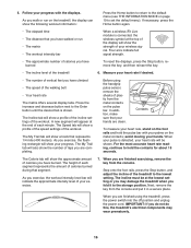
... a different speed and/or incline setting is an estimate of the number of the treadmill during the workout. In addition, if you manually change the speed or incline of calories that you are programmed for the current segment. To resume the workout, press the Start button or the Speed increase button. Measure your progress. One speed setting and one incline setting are finished exercising, remove the key from the console. Follow your weight. See step 6 on page...
... a different speed and/or incline setting is an estimate of the number of the treadmill during the workout. In addition, if you manually change the speed or incline of calories that you are programmed for the current segment. To resume the workout, press the Start button or the Speed increase button. Measure your progress. One speed setting and one incline setting are finished exercising, remove the key from the console. Follow your weight. See step 6 on page...
English Manual
Page 18
... walking belt will walk or run two demo workouts. Measure your progress in the iFit Live main screen. In addition, you will show the duration of the race. 7. When you select an iFit Live workout, the display will show a track and the number of laps you can also run , the approximate number of the trail you are finished exercising, remove the key from the console and press...
... walking belt will walk or run two demo workouts. Measure your progress in the iFit Live main screen. In addition, you will show the duration of the race. 7. When you select an iFit Live workout, the display will show a track and the number of laps you can also run , the approximate number of the trail you are finished exercising, remove the key from the console and press...
English Manual
Page 19
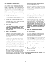
... buttons to select the manual main screen or the iFit Live screen as the default menu. 5. If an iFit Live module is connected, the display will begin to a stop. Press the Enter button to personalize console settings. To exit the information mode, remove the key from the console. 19 The walking belt will show the total number of miles (or kilometers) that keeps track of the following screens: 4. If the demo mode is turned...
... buttons to select the manual main screen or the iFit Live screen as the default menu. 5. If an iFit Live module is connected, the display will begin to a stop. Press the Enter button to personalize console settings. To exit the information mode, remove the key from the console. 19 The walking belt will show the total number of miles (or kilometers) that keeps track of the following screens: 4. If the demo mode is turned...
English Manual
Page 21
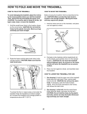
Moving the treadmill may require two people. 1. Then, remove the key and unplug the power cord. Bend your legs and keep your right hand. CAUTION: Make sure that the latch knob locks. 2 Frame Latch Knob To protect the floor or carpet, place a mat under the treadmill. CAUTION: Make sure that the latch knob is locked in the location shown by the arrow below. Hold the upper...
Moving the treadmill may require two people. 1. Then, remove the key and unplug the power cord. Bend your legs and keep your right hand. CAUTION: Make sure that the latch knob locks. 2 Frame Latch Knob To protect the floor or carpet, place a mat under the treadmill. CAUTION: Make sure that the latch knob is locked in the location shown by the arrow below. Hold the upper...
English Manual
Page 22
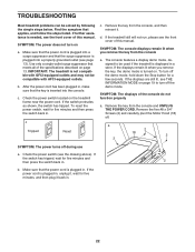
... key from the console, and then reinsert it back in . 2 b. Use only a single-outlet surge suppressor that the power cord is plugged into a properly grounded outlet (see page 13). b. If the treadmill still will not run, please see THE INFORMATION MODE on a. To turn off the demo mode, hold down the Stop button for five minutes and then press the switch back in . 22 If the displays...
... key from the console, and then reinsert it back in . 2 b. Use only a single-outlet surge suppressor that the power cord is plugged into a properly grounded outlet (see page 13). b. If the treadmill still will not run, please see THE INFORMATION MODE on a. To turn off the demo mode, hold down the Stop button for five minutes and then press the switch back in . 22 If the displays...
English Manual
Page 23
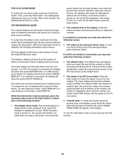
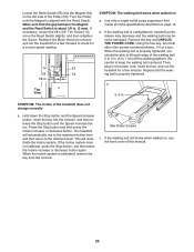
b. Then, plug in the power cord, insert the key, and run the treadmill for a few minutes. b 2-3 in . (3 mm). Press the Stop button and then press the Incline increase or decrease button. If the walking belt still slows when walked on, see the front cover of the Pulley (53). Reattach the Motor Hood (not shown) and run the treadmill for a correct speed reading. 14 53 55 54 1/8 in . (5 to keep the walking belt centered...
b. Then, plug in the power cord, insert the key, and run the treadmill for a few minutes. b 2-3 in . (3 mm). Press the Stop button and then press the Incline increase or decrease button. If the walking belt still slows when walked on, see the front cover of the Pulley (53). Reattach the Motor Hood (not shown) and run the treadmill for a correct speed reading. 14 53 55 54 1/8 in . (5 to keep the walking belt centered...
English Manual
Page 24
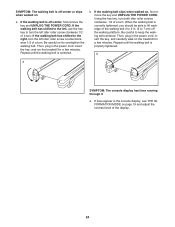
... power cord, insert the key, and run the treadmill for a few minutes. SYMPTOM: The walking belt is off-center or slips when walked on , first remove the key and UNPLUG THE POWER CORD. Repeat until the walking belt is properly tightened. If the walking belt has shifted to the left, use the hex key to the right, turn the left idler roller screw clockwise 1/2 of a turn . Then, plug in the console display, see THE INFORMATION MODE on the treadmill...
... power cord, insert the key, and run the treadmill for a few minutes. SYMPTOM: The walking belt is off-center or slips when walked on , first remove the key and UNPLUG THE POWER CORD. Repeat until the walking belt is properly tightened. If the walking belt has shifted to the left, use the hex key to the right, turn the left idler roller screw clockwise 1/2 of a turn . Then, plug in the console display, see THE INFORMATION MODE on the treadmill...
English Manual
Page 25
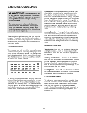
... years). The pulse sensor is the key to use your heart rate as you exercise-never hold your age at a low intensity level for fat burning and aerobic exercise. The three numbers listed above your age define your physician. During the first few minutes of your body begin to achieving results. Cooling Down-Finish with pre-existing health problems. The pulse sensor is activity that...
... years). The pulse sensor is the key to use your heart rate as you exercise-never hold your age at a low intensity level for fat burning and aerobic exercise. The three numbers listed above your age define your physician. During the first few minutes of your body begin to achieving results. Cooling Down-Finish with pre-existing health problems. The pulse sensor is activity that...
English Manual
Page 26
... Right Platform Support Reed Switch Clamp Drive Roller/Pulley Magnet Reed Switch Wire Tie Frame Storage Latch Drive Motor Motor Belt Right Rear Foot Right Frame Cover Left Frame Cover Hex Key Incline Frame Spacer Incline Motor Spacer Incline Motor Incline Frame Frame Spacer Controller Electronics Plate Belly Pan Post Power Switch Power Cord Grommet Belly Pan Upright Wire Left Upright Cap Right Upright Cap Handrail Cap Left Handrail Right Handrail Left Base Cover Right Base Cover Caution Decal Pulse Bar Top Pulse Bar Bottom Left Upright Right Upright Ground Wire Base Left...
... Right Platform Support Reed Switch Clamp Drive Roller/Pulley Magnet Reed Switch Wire Tie Frame Storage Latch Drive Motor Motor Belt Right Rear Foot Right Frame Cover Left Frame Cover Hex Key Incline Frame Spacer Incline Motor Spacer Incline Motor Incline Frame Frame Spacer Controller Electronics Plate Belly Pan Post Power Switch Power Cord Grommet Belly Pan Upright Wire Left Upright Cap Right Upright Cap Handrail Cap Left Handrail Right Handrail Left Base Cover Right Base Cover Caution Decal Pulse Bar Top Pulse Bar Bottom Left Upright Right Upright Ground Wire Base Left...
English Manual
Page 32
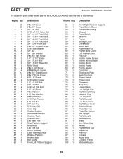
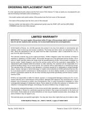
... REPLACEMENT PARTS To order replacement parts, please see the PART LIST and the EXPLODED DRAWING near the end of this manual) LIMITED WARRANTY IMPORTANT: You must be the customerʼs responsibility. To help us : • the model number and serial number of the product (see the front cover of this manual) • the name of the product (see the front cover of this manual) • the key number and...
... REPLACEMENT PARTS To order replacement parts, please see the PART LIST and the EXPLODED DRAWING near the end of this manual) LIMITED WARRANTY IMPORTANT: You must be the customerʼs responsibility. To help us : • the model number and serial number of the product (see the front cover of this manual) • the name of the product (see the front cover of this manual) • the key number and...


