
Uk Manual
Page 2
... using the exercise cycle. 7. Use the exercise cycle indoors on the exercise cycle. The pulse sensor is the responsibility of 12 and pets away from moisture and dust. Inspect and properly tighten all times. 6. TABLE OF CONTENTS IMPORTANT PRECAUTIONS 2 BEFORE YOU BEGIN 3 ASSEMBLY 4 HOW TO OPERATE THE EXERCISE CYCLE 8 MAINTENANCE AND TROUBLESHOOTING 19 CONDITIONING GUIDELINES 21 PART LIST 22 EXPLODED DRAWING 23 ORDERING REPLACEMENT PARTS Back Cover...
... using the exercise cycle. 7. Use the exercise cycle indoors on the exercise cycle. The pulse sensor is the responsibility of 12 and pets away from moisture and dust. Inspect and properly tighten all times. 6. TABLE OF CONTENTS IMPORTANT PRECAUTIONS 2 BEFORE YOU BEGIN 3 ASSEMBLY 4 HOW TO OPERATE THE EXERCISE CYCLE 8 MAINTENANCE AND TROUBLESHOOTING 19 CONDITIONING GUIDELINES 21 PART LIST 22 EXPLODED DRAWING 23 ORDERING REPLACEMENT PARTS Back Cover...
Uk Manual
Page 3
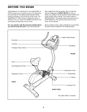
... Console Handgrip Pulse Sensor Seat Seat Adjustment Knob Adjustment Knob REAR Water Bottle Holder* Handlebar FRONT Adjustment Knob Pedal/Strap Wheel RIGHT SIDE Levelling Foot *No water bottle is HREVEX24030. If you , please note the product model number and serial number before you enjoy this healthful exercise in the drawing below. The serial number can be found on a decal attached to let you use the exercise cycle. Before reading further, please familiarise yourself with the parts...
... Console Handgrip Pulse Sensor Seat Seat Adjustment Knob Adjustment Knob REAR Water Bottle Holder* Handlebar FRONT Adjustment Knob Pedal/Strap Wheel RIGHT SIDE Levelling Foot *No water bottle is HREVEX24030. If you , please note the product model number and serial number before you enjoy this healthful exercise in the drawing below. The serial number can be found on a decal attached to let you use the exercise cycle. Before reading further, please familiarise yourself with the parts...
Uk Manual
Page 4
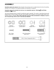
... the small parts used in parenthesis below to the key number of the part, from the PART LIST on page 22. The second number refers to see if it has been pre-attached. Place all parts of the packing materials until assembly is not in a cleared area and remove the packing materials. Assembly requires the included tools and your own adjustable spanners screwdriver . ASSEMBLY Assembly requires...
... the small parts used in parenthesis below to the key number of the part, from the PART LIST on page 22. The second number refers to see if it has been pre-attached. Place all parts of the packing materials until assembly is not in a cleared area and remove the packing materials. Assembly requires the included tools and your own adjustable spanners screwdriver . ASSEMBLY Assembly requires...
Uk Manual
Page 5
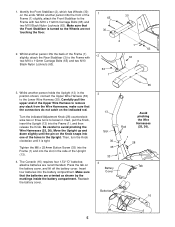
... the markings inside the battery compartment. Tighten the M6 x 25.4mm Button Screw (33) into the Frame (1) and into the battery compartment. Insert four batteries into the slot in the side of the Frame (1) slightly, attach the Rear Stabiliser (3) to the Lower Wire Harness (35). Move the Upright up and down slightly until it . Next, pull the Knob, insert the Upright (13) into one...
... the markings inside the battery compartment. Tighten the M6 x 25.4mm Button Screw (33) into the Frame (1) and into the battery compartment. Insert four batteries into the slot in the side of the Frame (1) slightly, attach the Rear Stabiliser (3) to the Lower Wire Harness (35). Move the Upright up and down slightly until it . Next, pull the Knob, insert the Upright (13) into one...
Uk Manual
Page 6
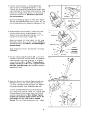
... indicated Adjustment Knob (28) counterclockwise two or three turns to loosen it . Then, insert the metal tube on the Console (16). 5. Next, pull the Knob, insert the Seat Post (5) into the opening in the indicated location. 7. Connect the wire harness on the Handgrip Pulse 5 Sensor (15) to the underside of the console. Note: The Nylon Locknuts and the Split Washers may be pre-attached...
... indicated Adjustment Knob (28) counterclockwise two or three turns to loosen it . Then, insert the metal tube on the Console (16). 5. Next, pull the Knob, insert the Seat Post (5) into the opening in the indicated location. 7. Connect the wire harness on the Handgrip Pulse 5 Sensor (15) to the underside of the console. Note: The Nylon Locknuts and the Split Washers may be pre-attached...

Uk Manual
Page 7
... receiver (B). B Cylinder Jack A 7 Plug the jumper wire (A) into the Right Crank Arm. Remove the indicated short screws and long screws from the back of the Console (16) with the chest pulse sensor. 1. Make sure that all parts are pinched. Identify the Left Pedal (24), which is completed, some extra parts may be left over. Orient the receiver as possible. 9. Adjust the Left Pedal Strap (25) to the...
... receiver (B). B Cylinder Jack A 7 Plug the jumper wire (A) into the Right Crank Arm. Remove the indicated short screws and long screws from the back of the Console (16) with the chest pulse sensor. 1. Make sure that all parts are pinched. Identify the Left Pedal (24), which is completed, some extra parts may be left over. Orient the receiver as possible. 9. Adjust the Left Pedal Strap (25) to the...
Uk Manual
Page 8
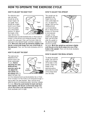
... the straps back onto the tabs. Move the seat bracket forward and back- ward slightly until it is not loosened enough, it (if the knob is tight. Knob Next, pull the knob, slide the upright to the desired position, and press the ends of the holes in the lowest Post position. Then, turn the knob clockwise until the pin on the pedals. Pedal Strap...
... the straps back onto the tabs. Move the seat bracket forward and back- ward slightly until it is not loosened enough, it (if the knob is tight. Knob Next, pull the knob, slide the upright to the desired position, and press the ends of the holes in the lowest Post position. Then, turn the knob clockwise until the pin on the pedals. Pedal Strap...
Uk Manual
Page 9
... changes the pedalling resistance and prompts you exercise. Using a stereo audio cable (available at electronics stores), you can even measure your pace as a personal trainer coaches you through an effective workout. Explore www.iFIT.com for more enjoyable and effective. In addition, the console features two heart rate programs that change the pedalling resistance and prompt you can be adjusted with a touch of a button. Note: For information about an optional chest pulse sensor...
... changes the pedalling resistance and prompts you exercise. Using a stereo audio cable (available at electronics stores), you can even measure your pace as a personal trainer coaches you through an effective workout. Explore www.iFIT.com for more enjoyable and effective. In addition, the console features two heart rate programs that change the pedalling resistance and prompt you can be adjusted with a touch of a button. Note: For information about an optional chest pulse sensor...
Uk Manual
Page 10
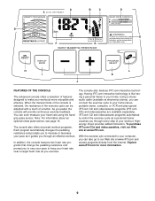
... you increase or decrease your speed is currently shown. When the manual mode is off, pressing this button will show a target pace. when your pedalling pace. buttons-These buttons control the resistance of the console, see page 11. There are also used to select the unit of the display will reset the display. To use the handgrip pulse sensor or the optional chest pulse sensor). To use a preset program, see page 18. 10...
... you increase or decrease your speed is currently shown. When the manual mode is off, pressing this button will show a target pace. when your pedalling pace. buttons-These buttons control the resistance of the console, see page 11. There are also used to select the unit of the display will reset the display. To use the handgrip pulse sensor or the optional chest pulse sensor). To use a preset program, see page 18. 10...
Uk Manual
Page 11
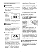
... wear the optional chest pulse sensor and hold the handgrips, the display will show your current speed, the elapsed time, the current resistance level, the approximate number of the elapsed time. HOW TO USE THE MANUAL MODE 1 Turn on page 5). Note: The console requires four 1.5V "D" batteries (see assembly step 4 on the console. To turn off. ed. gram has been selected, select the manual mode by pressing the + and - There...
... wear the optional chest pulse sensor and hold the handgrips, the display will show your current speed, the elapsed time, the current resistance level, the approximate number of the elapsed time. HOW TO USE THE MANUAL MODE 1 Turn on page 5). Note: The console requires four 1.5V "D" batteries (see assembly step 4 on the console. To turn off. ed. gram has been selected, select the manual mode by pressing the + and - There...
Uk Manual
Page 12
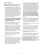
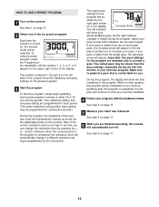
... current resistance level is turned on, the manual mode will automatically turn off. See step 5 on page 11. 12 The profiles numbered 1 through 6 on page 11. 5 Measure your exercise program. To start the program, simply begin pedalling. button. if your pace so that is programmed for the preset programs. 3 Start the program. Make sure to provide a goal. See step 4 on the left indicator will automatically change if a different resistance setting is...
... current resistance level is turned on, the manual mode will automatically turn off. See step 5 on page 11. 12 The profiles numbered 1 through 6 on page 11. 5 Measure your exercise program. To start the program, simply begin pedalling. button. if your pace so that is programmed for the preset programs. 3 Start the program. Make sure to provide a goal. See step 4 on the left indicator will automatically change if a different resistance setting is...
Uk Manual
Page 13
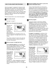
... will change in height to prompt you must use a heart rate program. 1 Turn on , the manual mode will flash in the display instead of your heart rate to operate properly. To use a heart rate program, you to hold the handgrip pulse sensor or wear the optional chest pulse sensor, the console will compare your heart rate. 5 Start the program. The left indicator will show your heart rate near a target heart rate that you selected program 8, the letters PLS and a target heart rate setting...
... will change in height to prompt you must use a heart rate program. 1 Turn on , the manual mode will flash in the display instead of your heart rate to operate properly. To use a heart rate program, you to hold the handgrip pulse sensor or wear the optional chest pulse sensor, the console will compare your heart rate. 5 Start the program. The left indicator will show your heart rate near a target heart rate that you selected program 8, the letters PLS and a target heart rate setting...
Uk Manual
Page 14
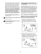
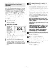
... to pedal at the same height. See page 16 for connecting instructions. Plug the other side of your exercise program. if your pace is slower than the target pace, the decrease arrow will automatically turn off. See step 4 on your CD player. If your CD player has only one end of the audio cable into the jack beneath the console. A. Plug your...
... to pedal at the same height. See page 16 for connecting instructions. Plug the other side of your exercise program. if your pace is slower than the target pace, the decrease arrow will automatically turn off. See step 4 on your CD player. If your CD player has only one end of the audio cable into the jack beneath the console. A. Plug your...
Uk Manual
Page 17
... video program. 1 Turn on the console. If you are finished exercising, the console will function in almost the same way as a preset program (see step 3 on page 12). Note: If the resistance of the display. 3 Insert the iFIT.com CD or videocassette. Note: For information about to use iFIT.com CDs or videocassettes, the exercise cycle must be selected. To select the iFIT.com mode, press the iFIT.com button...
... video program. 1 Turn on the console. If you are finished exercising, the console will function in almost the same way as a preset program (see step 3 on page 12). Note: If the resistance of the display. 3 Insert the iFIT.com CD or videocassette. Note: For information about to use iFIT.com CDs or videocassettes, the exercise cycle must be selected. To select the iFIT.com mode, press the iFIT.com button...
Uk Manual
Page 18
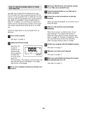
... console will begin. 7 Return to play iFIT.com audio and video programs directly from our Web site. 1 Turn on page 11. 10 When you to the exercise cycle and begin . See step 1 on page 16. See step 5 on the console. To use a program from the internet. In addition, you start an internet connection. 18 When you must be selected. To select the iFIT.com mode, press the iFIT.com button...
... console will begin. 7 Return to play iFIT.com audio and video programs directly from our Web site. 1 Turn on page 11. 10 When you to the exercise cycle and begin . See step 1 on page 16. See step 5 on the console. To use a program from the internet. In addition, you start an internet connection. 18 When you must be selected. To select the iFIT.com mode, press the iFIT.com button...
Uk Manual
Page 19
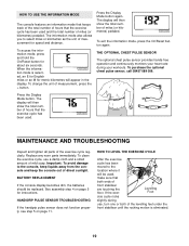
... information mode, press and hold the On/Reset button for instructions. The display will then show the total number of miles (or kilometres) pedaled. MAINTENANCE AND TROUBLESHOOTING Inspect and tighten all parts of direct sunlight. If the exer- To purchase the optional chest pulse sensor, call 08457 089 009. See assembly step 4 on page 11. HANDGRIP PULSE SENSOR TROUBLESHOOTING If the handgrip pulse sensor does not function properly, see step 5 on page 5 for about six seconds. Replace...
... information mode, press and hold the On/Reset button for instructions. The display will then show the total number of miles (or kilometres) pedaled. MAINTENANCE AND TROUBLESHOOTING Inspect and tighten all parts of direct sunlight. If the exer- To purchase the optional chest pulse sensor, call 08457 089 009. See assembly step 4 on page 11. HANDGRIP PULSE SENSOR TROUBLESHOOTING If the handgrip pulse sensor does not function properly, see step 5 on page 5 for about six seconds. Replace...
Uk Manual
Page 20
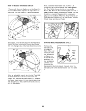
... ADJUST THE REED SWITCH If the console does not display correct feedback, the reed switch should be moved on the front stabiliser. Retighten the Screw. Using an adjustable wrench, turn the Left Pedal (24) clockwise and remove it . Next, remove the two Screws (66) from the Magnet. Turn the Left Crank Arm (42) until the exer- Turn the Crank for a moment. Remove the Round Head Screw (71) from the left side of the exercise...
... ADJUST THE REED SWITCH If the console does not display correct feedback, the reed switch should be moved on the front stabiliser. Retighten the Screw. Using an adjustable wrench, turn the Left Pedal (24) clockwise and remove it . Next, remove the two Screws (66) from the Magnet. Turn the Left Crank Arm (42) until the exer- Turn the Crank for a moment. Remove the Round Head Screw (71) from the left side of the exercise...
Uk Manual
Page 21
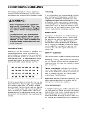
... accuracy of the chart (ages are your "training zone." the middle number is the recommended heart rate for successful results. After a few minutes of oxygen for aerobic exercise. Remember, the key to prevent post-exercise problems. EXERCISE FREQUENCY To maintain or improve your condition, plan three workouts each week, if desired. Remember that requires large amounts of exercise, your body uses easily accessible carbohydrate...
... accuracy of the chart (ages are your "training zone." the middle number is the recommended heart rate for successful results. After a few minutes of oxygen for aerobic exercise. Remember, the key to prevent post-exercise problems. EXERCISE FREQUENCY To maintain or improve your condition, plan three workouts each week, if desired. Remember that requires large amounts of exercise, your body uses easily accessible carbohydrate...
Uk Manual
Page 22
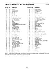
.../Handgrip Pulse Sensor 16 1 Console 17 1 Left Side Shield 18 1 Right Side Shield 19 1 Side Shield Cover 20 1 Seat Upright Bushing 21 1 Crank Assembly 22 1 Reed Switch Clamp 23 2 M4 x 5mm Screw 24 1 Left Pedal 25 1 Left Pedal Strap 26 1 Right Pedal 27 1 Right Pedal Strap 28 2 Adjustment Knob 29 2 M6 x 72mm Button Screw 30 2 Wheel 31 1 Left Front Endcap 32 1 Right Front Endcap 33 1 M6 x 25.4mm Button Screw 34 1 Adjustment Motor 35 1 Lower Wire Harness...
.../Handgrip Pulse Sensor 16 1 Console 17 1 Left Side Shield 18 1 Right Side Shield 19 1 Side Shield Cover 20 1 Seat Upright Bushing 21 1 Crank Assembly 22 1 Reed Switch Clamp 23 2 M4 x 5mm Screw 24 1 Left Pedal 25 1 Left Pedal Strap 26 1 Right Pedal 27 1 Right Pedal Strap 28 2 Adjustment Knob 29 2 M6 x 72mm Button Screw 30 2 Wheel 31 1 Left Front Endcap 32 1 Right Front Endcap 33 1 M6 x 25.4mm Button Screw 34 1 Adjustment Motor 35 1 Lower Wire Harness...
Uk Manual
Page 24
... the following information: • the MODEL NUMBER of the product (HREVEX24030) • the NAME of the product (HealthRider® R 790X exercise cycle) • the SERIAL NUMBER of the product (see the front cover of this manual) • the KEY NUMBER and DESCRIPTION of the part(s) (see page 22) HealthRider is a registered trademark of ICON Health & Fitness, Inc. Part No. 198532 R0903A Printed in China © 2003 ICON Health & Fitness, Inc.
... the following information: • the MODEL NUMBER of the product (HREVEX24030) • the NAME of the product (HealthRider® R 790X exercise cycle) • the SERIAL NUMBER of the product (see the front cover of this manual) • the KEY NUMBER and DESCRIPTION of the part(s) (see page 22) HealthRider is a registered trademark of ICON Health & Fitness, Inc. Part No. 198532 R0903A Printed in China © 2003 ICON Health & Fitness, Inc.

