

English Manual
Page 1
... instructions in the space above ) before using this equipment. HREL74907.0 Serial No. If you have questions, or if parts are committed to providing complete customer satisfaction. USER'S MANUAL Visit our website at www.healthrider.com new products, prizes, fitness tips, and much more! IMPORTANT: You must note the product model number and serial number (see the drawing above for future reference. MST Sat. 8 a.m.-4 p.m. Serial Number...
... instructions in the space above ) before using this equipment. HREL74907.0 Serial No. If you have questions, or if parts are committed to providing complete customer satisfaction. USER'S MANUAL Visit our website at www.healthrider.com new products, prizes, fitness tips, and much more! IMPORTANT: You must note the product model number and serial number (see the drawing above for future reference. MST Sat. 8 a.m.-4 p.m. Serial Number...

English Manual
Page 2
... this manual and request a free replacement decal. Apply the decal in the indicated location. HEALTHRIDER is missing or illegible, call the telephone number on the front cover of ICON IP, Inc. 2 TABLE OF CONTENTS WARNING DECAL PLACEMENT 2 IMPORTANT PRECAUTIONS 3 BEFORE YOU BEGIN 4 ASSEMBLY 5 HOW TO USE THE ELLIPTICAL EXERCISER 11 MAINTENANCE AND TROUBLESHOOTING 17 EXERCISE GUIDELINES 18 PART LIST 20 EXPLODED DRAWING 21 ORDERING REPLACEMENT PARTS Back Cover LIMITED WARRANTY Back Cover WARNING...
... this manual and request a free replacement decal. Apply the decal in the indicated location. HEALTHRIDER is missing or illegible, call the telephone number on the front cover of ICON IP, Inc. 2 TABLE OF CONTENTS WARNING DECAL PLACEMENT 2 IMPORTANT PRECAUTIONS 3 BEFORE YOU BEGIN 4 ASSEMBLY 5 HOW TO USE THE ELLIPTICAL EXERCISER 11 MAINTENANCE AND TROUBLESHOOTING 17 EXERCISE GUIDELINES 18 PART LIST 20 EXPLODED DRAWING 21 ORDERING REPLACEMENT PARTS Back Cover LIMITED WARRANTY Back Cover WARNING...

English Manual
Page 3
... and instructions in this manual. 3 Hold the handgrip pulse sensor or the handlebars when mounting, dismounting, or using your elliptical exerciser only as an exercise aid in determining heart rate trends in a commercial, rental, or institutional setting. 4. The pulse sensor is the responsibility of all users of the elliptical exerciser are adequately informed of the owner to a stop immediately and cool down. 14. The pulse sensor is enough clearance around your elliptical exerciser...
... and instructions in this manual. 3 Hold the handgrip pulse sensor or the handlebars when mounting, dismounting, or using your elliptical exerciser only as an exercise aid in determining heart rate trends in a commercial, rental, or institutional setting. 4. The pulse sensor is the responsibility of all users of the elliptical exerciser are adequately informed of the owner to a stop immediately and cool down. 14. The pulse sensor is enough clearance around your elliptical exerciser...
English Manual
Page 4
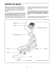
... any service needed under warranty, you must register the elliptical exerciser at home more effective and enjoyable. If you use the elliptical exerciser. Before reading further, please familiarize yourself with the parts that are shown on the front cover of features designed to make your benefit, read this manual. For your workouts at www.healthriderservice.com/registration. The model number and the location of this manual carefully...
... any service needed under warranty, you must register the elliptical exerciser at home more effective and enjoyable. If you use the elliptical exerciser. Before reading further, please familiarize yourself with the parts that are shown on the front cover of features designed to make your benefit, read this manual. For your workouts at www.healthriderservice.com/registration. The model number and the location of this manual carefully...
English Manual
Page 5
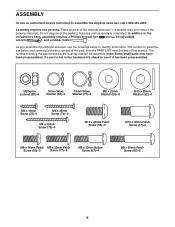
... packing materials until assembly is the quantity needed for assembly. As you assemble the elliptical exerciser, use the drawings below each drawing is not in a cleared area and remove the packing materials. If a part is the key number of the part, from the PART LIST near the end of the elliptical exerciser in the hardware kit, check to identify small parts. In addition to assemble the elliptical exerciser, call 1-800...
... packing materials until assembly is the quantity needed for assembly. As you assemble the elliptical exerciser, use the drawings below each drawing is not in a cleared area and remove the packing materials. If a part is the key number of the part, from the PART LIST near the end of the elliptical exerciser in the hardware kit, check to identify small parts. In addition to assemble the elliptical exerciser, call 1-800...

English Manual
Page 6
... grease to the Pivot Axle (41). Apply a generous amount of the Frame (1) with an M8 x 25mm Patch Screw (77), a Pivot Axle Cover (44), and an M8 x 25mm Washer (54). Slide the Right Upper Body Arm ...Wire Harness (73) upward through the Frame (1). Attach the Left Upper Body Arm (23) in the same way. 1 8 57 2. 1. To make assembly easier, read the 1 information on page 5 before you begin assembling the elliptical exerciser. Attach a Wheel (8) to one side of the included grease to a 16mm Wave Washer (66). Attach the Right Upper Body Arm with an M10 x 35mm Patch Screw...
... grease to the Pivot Axle (41). Apply a generous amount of the Frame (1) with an M8 x 25mm Patch Screw (77), a Pivot Axle Cover (44), and an M8 x 25mm Washer (54). Slide the Right Upper Body Arm ...Wire Harness (73) upward through the Frame (1). Attach the Left Upper Body Arm (23) in the same way. 1 8 57 2. 1. To make assembly easier, read the 1 information on page 5 before you begin assembling the elliptical exerciser. Attach a Wheel (8) to one side of the included grease to a 16mm Wave Washer (66). Attach the Right Upper Body Arm with an M10 x 35mm Patch Screw...
English Manual
Page 7
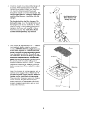
... the Wire Harness (73) during this , the console displays or other end of the power supply into an appropriate outlet that is properly installed in accordance with all the Patch Screws before inserting batteries into the Console. If you do not do this step. Then, slide the Upright Cover upward and attach the Upright to room temperature before tightening any of batteries. Note: The Console (4) can...
... the Wire Harness (73) during this , the console displays or other end of the power supply into an appropriate outlet that is properly installed in accordance with all the Patch Screws before inserting batteries into the Console. If you do not do this step. Then, slide the Upright Cover upward and attach the Upright to room temperature before tightening any of batteries. Note: The Console (4) can...
English Manual
Page 8
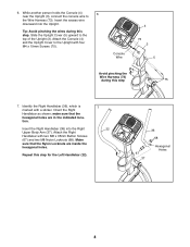
... Upright. Insert the excess wire downward into the Right Upper Body Arm (37). Identify the Right Handlebar (36), which is marked with four M4 x 19mm Screws (75). Orient the Right Handlebar as shown; Tip: Avoid pinching the wires during this step. Console Wire 4 73 3 5 Avoid pinching the Wire Harness (73) during this step 75 7. Attach the Console (4) and the Upright Cover to the Upright with a sticker. Attach...
... Upright. Insert the excess wire downward into the Right Upper Body Arm (37). Identify the Right Handlebar (36), which is marked with four M4 x 19mm Screws (75). Orient the Right Handlebar as shown; Tip: Avoid pinching the wires during this step. Console Wire 4 73 3 5 Avoid pinching the Wire Harness (73) during this step 75 7. Attach the Console (4) and the Upright Cover to the Upright with a sticker. Attach...
English Manual
Page 9
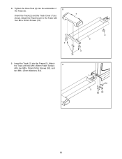
8. Attach 9 the Track with four M4 x 50mm Screws (76). 9 2 9 9 76 9. Attach the Track Cover to the Track with two M8 x 50mm Patch Screws (65), two M8 x 16mm Patch Screws (53), and two M8 x 25mm Washers (54). 1 54 2 65 53 9 Tighten the three Feet (9) into the Frame (1). Insert the Track (2) into the underside of 8 the Track (2). 7 Orient the Track (2) and the Track Cover (7) as shown.
8. Attach 9 the Track with four M4 x 50mm Screws (76). 9 2 9 9 76 9. Attach the Track Cover to the Track with two M8 x 50mm Patch Screws (65), two M8 x 16mm Patch Screws (53), and two M8 x 25mm Washers (54). 1 54 2 65 53 9 Tighten the three Feet (9) into the Frame (1). Insert the Track (2) into the underside of 8 the Track (2). 7 Orient the Track (2) and the Track Cover (7) as shown.

English Manual
Page 10
... Patch Screws (77), two Link Axle Covers (49), and two M8 x 25mm Washers (54). Also, apply a small amount of grease to a 16mm Wave Washer (66). Identify the Right Pedal Leg (38) and Right Link Arm (39) assembly, which are properly tightened. Apply a small amount of another person, slide the Right Pedal Leg (38) onto the right side of the elliptical exerciser. 37 Grease...
... Patch Screws (77), two Link Axle Covers (49), and two M8 x 25mm Washers (54). Also, apply a small amount of grease to a 16mm Wave Washer (66). Identify the Right Pedal Leg (38) and Right Link Arm (39) assembly, which are properly tightened. Apply a small amount of another person, slide the Right Pedal Leg (38) onto the right side of the elliptical exerciser. 37 Grease...
English Manual
Page 11
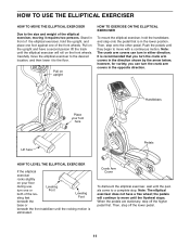
... move the elliptical exerciser to the desired location, and then lower it to the size and weight of the elliptical exerciser, moving it requires two persons. Pull on upright HOW TO EXERCISE ON THE ELLIPTICAL EXERCISER To mount the elliptical exerciser, hold the upright, and place one foot against one or both of the front wheels. Place your floor during use, Leveling turn in either direction. Note: The crank arm covers can turn the crank arm covers...
... move the elliptical exerciser to the desired location, and then lower it to the size and weight of the elliptical exerciser, moving it requires two persons. Pull on upright HOW TO EXERCISE ON THE ELLIPTICAL EXERCISER To mount the elliptical exerciser, hold the upright, and place one foot against one or both of the front wheels. Place your floor during use, Leveling turn in either direction. Note: The crank arm covers can turn the crank arm covers...

English Manual
Page 12
... make your heart rate using the handgrip pulse sensor. To use a calorie goal workout, see page 16. 12 When you use the manual mode of a button. The console has five calorie goal workouts designed to vary your pace while guiding you can even measure your workouts more effective and enjoyable. You can change the resistance of the pedals and prompt you to help you exercise, the console will display continuous exercise feedback...
... make your heart rate using the handgrip pulse sensor. To use a calorie goal workout, see page 16. 12 When you use the manual mode of a button. The console has five calorie goal workouts designed to vary your pace while guiding you can even measure your workouts more effective and enjoyable. You can change the resistance of the pedals and prompt you to help you exercise, the console will display continuous exercise feedback...

English Manual
Page 13
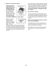
... the approximate number of calories you have pedaled and your pedaling pace, in revolutions per minute (rpm). As you have selected a workout, reselect the manual mode by pressing the Resistance increase and decrease buttons repeatedly. There are ten resistance levels. The right display- Follow your heart rate when you use the handgrip pulse sensor (see step 5 on the console, the displays will show the distance (total revolutions) you exercise, indicators will...
... the approximate number of calories you have pedaled and your pedaling pace, in revolutions per minute (rpm). As you have selected a workout, reselect the manual mode by pressing the Resistance increase and decrease buttons repeatedly. There are ten resistance levels. The right display- Follow your heart rate when you use the handgrip pulse sensor (see step 5 on the console, the displays will show the distance (total revolutions) you exercise, indicators will...
English Manual
Page 14
... pulse sensor, the display will be reset. 14 sor, remove the plas- Turn on the handgrip pulse sen- If the pedals do not move for up to squeeze the metal contacts tightly. If your heart rate, hold the contacts for about five minutes, the console will turn off automatically. The fan has high and low speed settings. Note: If the pedals do not move for several seconds, a series...
... pulse sensor, the display will be reset. 14 sor, remove the plas- Turn on the handgrip pulse sen- If the pedals do not move for up to squeeze the metal contacts tightly. If your heart rate, hold the contacts for about five minutes, the console will turn off automatically. The fan has high and low speed settings. Note: If the pedals do not move for several seconds, a series...

English Manual
Page 15
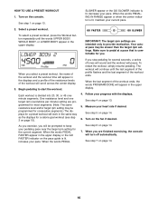
... resistance level and one target rpm (revolutions per minute) setting are finished exercising, the console will appear in the upper display. 4. See step 4 on the pace guide is comfortable for you are programmed for the current segment. When you . Press the Workout button repeatedly until the last segment of the profile flashes and the last segment of the pedals will pause. Each workout...
... resistance level and one target rpm (revolutions per minute) setting are finished exercising, the console will appear in the upper display. 4. See step 4 on the pace guide is comfortable for you are programmed for the current segment. When you . Press the Workout button repeatedly until the last segment of the profile flashes and the last segment of the pedals will pause. Each workout...
English Manual
Page 16
... stop pedaling for the current segment. See step 5 on page 14. 16 IMPORTANT: The target rpm settings are finished exercising, the console will continue until the words UPPER BODY, WHOLE BODY, or LOWER BODY appear in the upper display. 4. When the last segment of the workout ends. When you . Select a preset workout. Begin pedaling to keep your current pace. 2. The workout will turn off automatically. See step...
... stop pedaling for the current segment. See step 5 on page 14. 16 IMPORTANT: The target rpm settings are finished exercising, the console will continue until the words UPPER BODY, WHOLE BODY, or LOWER BODY appear in the upper display. 4. When the last segment of the workout ends. When you . Select a preset workout. Begin pedaling to keep your current pace. 2. The workout will turn off automatically. See step...

English Manual
Page 17
... crank arm cover. Loosen, but do not remove, the three 80 screws (A). Then, see the drawing below and locate the Reed Switch (21). ward between the Idler (12) and the pulley located on the Pulley (13). Pedal the elliptical exerciser until a thin film of the elliptical exerciser until the console displays correct feedback. wipe off any worn parts immediately. HOW TO ADJUST THE DRIVE BELT If the pedals slip while you hold the handgrip pulse sensor...
... crank arm cover. Loosen, but do not remove, the three 80 screws (A). Then, see the drawing below and locate the Reed Switch (21). ward between the Idler (12) and the pulley located on the Pulley (13). Pedal the elliptical exerciser until a thin film of the elliptical exerciser until the console displays correct feedback. wipe off any worn parts immediately. HOW TO ADJUST THE DRIVE BELT If the pedals slip while you hold the handgrip pulse sensor...

English Manual
Page 18
... minutes with your heart rate near the highest number in your body temperature, heart rate, and circulation in general. Training Zone Exercise-Exercise for successful results. During the first few months of regular exercise, you must exercise at least one day of time. Cooling down-Finish with pre-existing health problems. The pulse sensor is especially important for prolonged periods of rest between workouts. After a few...
... minutes with your heart rate near the highest number in your body temperature, heart rate, and circulation in general. Training Zone Exercise-Exercise for successful results. During the first few months of regular exercise, you must exercise at least one day of time. Cooling down-Finish with pre-existing health problems. The pulse sensor is especially important for prolonged periods of rest between workouts. After a few...

English Manual
Page 20
...Hex Key * - Grease Packet * - User's Manual Note: Specifications are not illustrated. 20 HREL74907.0 R1207A Key No. Qty. Description 1 1 Frame 2 1 Track 3 1 Upright 4 1 Console 5 1 Upright Cover 6 1 Water Bottle Holder 7 1 Track Cover 8 2 Wheel 9 3 Foot 10 1 Eddy Mechanism 11 1 Axle 12 1 Idler 13 1 Pulley 14 1 Crank 15 2 Crank Bearing 16 1 Resistance Motor 17 1 Resistance Cable 18 2 Magnet 19 2 Upper Body Bushing 20 1 Clamp 21 1 Reed Switch/Wire 22 1 Left Handlebar 23 1 Left Upper Body Arm 24 1 Left Pedal Leg...
...Hex Key * - Grease Packet * - User's Manual Note: Specifications are not illustrated. 20 HREL74907.0 R1207A Key No. Qty. Description 1 1 Frame 2 1 Track 3 1 Upright 4 1 Console 5 1 Upright Cover 6 1 Water Bottle Holder 7 1 Track Cover 8 2 Wheel 9 3 Foot 10 1 Eddy Mechanism 11 1 Axle 12 1 Idler 13 1 Pulley 14 1 Crank 15 2 Crank Bearing 16 1 Resistance Motor 17 1 Resistance Cable 18 2 Magnet 19 2 Upper Body Bushing 20 1 Clamp 21 1 Reed Switch/Wire 22 1 Left Handlebar 23 1 Left Upper Body Arm 24 1 Left Pedal Leg...

English Manual
Page 24
... specific legal rights. ICON is authorized by ICON. ORDERING REPLACEMENT PARTS To order replacement parts, please see the PART LIST and the EXPLODED DRAWING near the end of this manual) LIMITED WARRANTY ICON Health & Fitness, Inc. (ICON) warrants this product to you. There is limited in connection with the use or performance of the product or damages with respect to freight damage, abuse, misuse, improper or abnormal usage or repairs...
... specific legal rights. ICON is authorized by ICON. ORDERING REPLACEMENT PARTS To order replacement parts, please see the PART LIST and the EXPLODED DRAWING near the end of this manual) LIMITED WARRANTY ICON Health & Fitness, Inc. (ICON) warrants this product to you. There is limited in connection with the use or performance of the product or damages with respect to freight damage, abuse, misuse, improper or abnormal usage or repairs...


