
Technical Guide
Page 3
Hazardous voltage can cause severe injury and/or death. This product should be installed and serviced only by a qualified professional. All electrical wiring MUST be in conformance with all instructions in the owner's manual and on local electrical codes for electrocution and could result in injury or death. ...
Hazardous voltage can cause severe injury and/or death. This product should be installed and serviced only by a qualified professional. All electrical wiring MUST be in conformance with all instructions in the owner's manual and on local electrical codes for electrocution and could result in injury or death. ...
Technical Guide
Page 6
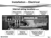
Installation - Electrical Internal wiring locations (fig 5) Wiring connection for incoming motor wires Wiring plug for relay connected controls & stop switch Wiring plug for wall mounted interface Wire connection for incoming line voltage (230v) Channel for running low voltage data cable Wiring plug for data link with Hayward/Goldline compatible software Controls Figure 5 Page 4
Installation - Electrical Internal wiring locations (fig 5) Wiring connection for incoming motor wires Wiring plug for relay connected controls & stop switch Wiring plug for wall mounted interface Wire connection for incoming line voltage (230v) Channel for running low voltage data cable Wiring plug for data link with Hayward/Goldline compatible software Controls Figure 5 Page 4

Technical Guide
Page 7
.../High Voltage High Voltage Wiring terminals (L1 & L2) 1. Voltage: 230 VAC, 60Hz, Single Phase. 2. Figure 6 Conduit Connections There are two on the pump. It is both bonded and grounded Page 5 One for high voltage and the other for an EcoStar that is data connected to a Hayward/Goldline control, voltage needs... to come directly from a breaker in the control, or in the case of an OnCommand, directly from the main or sub-panel and not from the filter pump relay. Breaker, wire size would be ...
.../High Voltage High Voltage Wiring terminals (L1 & L2) 1. Voltage: 230 VAC, 60Hz, Single Phase. 2. Figure 6 Conduit Connections There are two on the pump. It is both bonded and grounded Page 5 One for high voltage and the other for an EcoStar that is data connected to a Hayward/Goldline control, voltage needs... to come directly from a breaker in the control, or in the case of an OnCommand, directly from the main or sub-panel and not from the filter pump relay. Breaker, wire size would be ...
Technical Guide
Page 10
... channel within the motor electrical compartment Data Plug Figure 15 Figure 16 Figure 17 Page 8 You will need to procure a six wire data cable, as short as possible, and attach the wires to the data plug as shown (fig 16). 6. The data cable needs to the data plug (fig 15). Remove the...
... channel within the motor electrical compartment Data Plug Figure 15 Figure 16 Figure 17 Page 8 You will need to procure a six wire data cable, as short as possible, and attach the wires to the data plug as shown (fig 16). 6. The data cable needs to the data plug (fig 15). Remove the...

Technical Guide
Page 11
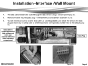
Attach the interface assembly to note the color and corresponding number on the data plug as shown, taking care to the mounting bracket with the data plug on the bottom of the bracket (fig 18). 8. Attach the six wires to the new data plug as you did with the two screws provided (fig 21). Secure the wall mounting bracket and route the six wire data cable through the channel on the pump (fig 20). Installation-Interface/Wall Mount 7. Figure 18 Figure 19 Figure 20 Figure 21 Page 9 Install the plug into the interface assembly (fig 19). 9.
Attach the interface assembly to note the color and corresponding number on the data plug as shown, taking care to the mounting bracket with the data plug on the bottom of the bracket (fig 18). 8. Attach the six wires to the new data plug as you did with the two screws provided (fig 21). Secure the wall mounting bracket and route the six wire data cable through the channel on the pump (fig 20). Installation-Interface/Wall Mount 7. Figure 18 Figure 19 Figure 20 Figure 21 Page 9 Install the plug into the interface assembly (fig 19). 9.

Technical Guide
Page 12
... forward Figure 23 Pump Terminal Data Plugs Page 10 Wire 7 on the pump to 2 on the controller, 8 on the pump to 3 on the controller and 1 on 7 EcoStar is data connected to a Hayward/Goldline control, voltage needs to operate the EcoStar Aqua Logic/Pro Logic/Aqua Plus v2.65 or ...Remove the two data plugs (COMBUS & DISPLAY) from the wiring compartment (fig 23) and the 4 connector data plug from the main or sub- Installation-Hayward/Goldline Controls (Compatible software shown below) 1. Maximum 500‟ for an EcoStar that is not needed in the case of an OnCommand, ...
... forward Figure 23 Pump Terminal Data Plugs Page 10 Wire 7 on the pump to 2 on the controller, 8 on the pump to 3 on the controller and 1 on 7 EcoStar is data connected to a Hayward/Goldline control, voltage needs to operate the EcoStar Aqua Logic/Pro Logic/Aqua Plus v2.65 or ...Remove the two data plugs (COMBUS & DISPLAY) from the wiring compartment (fig 23) and the 4 connector data plug from the main or sub- Installation-Hayward/Goldline Controls (Compatible software shown below) 1. Maximum 500‟ for an EcoStar that is not needed in the case of an OnCommand, ...

Technical Guide
Page 14
One side of the 24 VAC connection on the pump terminal needs to be wired to the 3. Filter Pump Replay AUX Relay AUX Relay AUX Relay Fig 25 Page 12 the pump terminal needs to the Load side of 4. Installation-Relay Connected Controls (Non Hayward/Goldline compatible software & third party controls) 2. 1, 3 and 5 from the pump terminal needs to be wired to be line side of the relays in series as shown (fig wired with 2, 4 & 6 on the pump terminal as shown (fig 25). The other leg of the 24 VAC connection on each control relays as shown (fig 25). 25).
One side of the 24 VAC connection on the pump terminal needs to be wired to the 3. Filter Pump Replay AUX Relay AUX Relay AUX Relay Fig 25 Page 12 the pump terminal needs to the Load side of 4. Installation-Relay Connected Controls (Non Hayward/Goldline compatible software & third party controls) 2. 1, 3 and 5 from the pump terminal needs to be wired to be line side of the relays in series as shown (fig wired with 2, 4 & 6 on the pump terminal as shown (fig 25). The other leg of the 24 VAC connection on each control relays as shown (fig 25). 25).

Technical Guide
Page 16
Installation-Remote Stop Switch 1. Note: The emergency switch needs to be wired to the e-switch for both NO and NC (normally Closed). One side of the 24 VAC on the pump terminal as shown (...fig 29). 2. Terminal 7 on the pump terminal and the other leg of the 24 VAC on the pump terminal needs to be wired to 8 on the pump terminal need to be a latching style that is completed and the pump will shut down operation. When the switch...NO). Remote stop switch purchased separately Fig 29 Page 14 Refer to the emergency switch (fig 29). Some switches have wiring for its internal...
Installation-Remote Stop Switch 1. Note: The emergency switch needs to be wired to the e-switch for both NO and NC (normally Closed). One side of the 24 VAC on the pump terminal as shown (...fig 29). 2. Terminal 7 on the pump terminal and the other leg of the 24 VAC on the pump terminal needs to be wired to 8 on the pump terminal need to be a latching style that is completed and the pump will shut down operation. When the switch...NO). Remote stop switch purchased separately Fig 29 Page 14 Refer to the emergency switch (fig 29). Some switches have wiring for its internal...
Technical Guide
Page 35
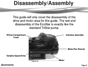
The wet end disassembly of the drive and motor area for this guide. Wiring Compartment Cover Interface Assembly Variable Speed Drive Figure 63 Motor/Fan Shroud Motor Page 33 Disassembly/Assembly This guide will only cover the disassembly of the EcoStar is exactly like the standard TriStar pump.
The wet end disassembly of the drive and motor area for this guide. Wiring Compartment Cover Interface Assembly Variable Speed Drive Figure 63 Motor/Fan Shroud Motor Page 33 Disassembly/Assembly This guide will only cover the disassembly of the EcoStar is exactly like the standard TriStar pump.

Technical Guide
Page 36
Figure 64 Figure 65 Page 34 Disassembly/Assembly 1. Remove the screw as shown (fig 65). Shut down power to the pump by moving the breaker supplying power to the pump to the off position. 2. Remove the wiring compartment cover as shown (fig 64).
Figure 64 Figure 65 Page 34 Disassembly/Assembly 1. Remove the screw as shown (fig 65). Shut down power to the pump by moving the breaker supplying power to the pump to the off position. 2. Remove the wiring compartment cover as shown (fig 64).

Technical Guide
Page 38
Note the color designation for each side) using a ¼" socket as shown (fig 69 & 70). Figure 69 Figure 70 Figure 71 Figure 72 Page 36 Make sure during reassembly to tighten these screws fully as they act as shown. Remove the four hex head screws (two on each spade when reassembling (fig 71 & 72). Pull the three wire connectors off the spade terminals as the ground between the drive and the motor. 7. Disassembly/Assembly 6.
Note the color designation for each side) using a ¼" socket as shown (fig 69 & 70). Figure 69 Figure 70 Figure 71 Figure 72 Page 36 Make sure during reassembly to tighten these screws fully as they act as shown. Remove the four hex head screws (two on each spade when reassembling (fig 71 & 72). Pull the three wire connectors off the spade terminals as the ground between the drive and the motor. 7. Disassembly/Assembly 6.

Technical Guide
Page 39
... bottom of the three wires individually through the hole provided (fig 73). 9. Disassembly/Assembly 8. Lift the drive assembly partially off the motor and carefully pull each of the drive is one sealed unit and cannot be disassembled. During reassembly make sure all three wires through the hole provided ...to pull all three wires are pulled completely through the hole as an assembly. Make sure any debris is replaced as you may cause ...
... bottom of the three wires individually through the hole provided (fig 73). 9. Disassembly/Assembly 8. Lift the drive assembly partially off the motor and carefully pull each of the drive is one sealed unit and cannot be disassembled. During reassembly make sure all three wires through the hole provided ...to pull all three wires are pulled completely through the hole as an assembly. Make sure any debris is replaced as you may cause ...

Technical Guide
Page 44
... problems including seals, gaskets, impellers, etc along with the VSC and Motor. Motor airflow path should be no issues remove the Blue, Black and Red wires (page 4) from lead to ground. Follow disassembly/assembly procedures (pages 32-37). If line voltage is drawing excessive current. There should be between 0.5 and 1.0 ohms...
... problems including seals, gaskets, impellers, etc along with the VSC and Motor. Motor airflow path should be no issues remove the Blue, Black and Red wires (page 4) from lead to ground. Follow disassembly/assembly procedures (pages 32-37). If line voltage is drawing excessive current. There should be between 0.5 and 1.0 ohms...

Technical Guide
Page 46
... that the drive was not able to start three times before stall error is being controlled via data link to a Hayward/Goldline Controller, disconnect the com ground wire between interface and drive. Check motor connections to drive (page 4) to Start. If no continuity. Ohms reading should ...the motor. If they are connected correctly (page 10). If error still exists remove all (0) check connection between terminal 1 with EcoStar and terminal 4 with Hayward/Goldline Control (page 10). Check values in Diagnosis menu and if they are outside limits, replace motor. Check to be no change...
... that the drive was not able to start three times before stall error is being controlled via data link to a Hayward/Goldline Controller, disconnect the com ground wire between interface and drive. Check motor connections to drive (page 4) to Start. If no continuity. Ohms reading should ...the motor. If they are connected correctly (page 10). If error still exists remove all (0) check connection between terminal 1 with EcoStar and terminal 4 with Hayward/Goldline Control (page 10). Check values in Diagnosis menu and if they are outside limits, replace motor. Check to be no change...

Technical Guide
Page 47
... shaft for potential air leaks or obstructions and corrected. Indicates the pump was not able to lead. If free, remove the Blue, Black and Red wires (page 4) from lead to prime within range, replace drive. If any of movement.
... shaft for potential air leaks or obstructions and corrected. Indicates the pump was not able to lead. If free, remove the Blue, Black and Red wires (page 4) from lead to prime within range, replace drive. If any of movement.

Technical Guide
Page 48
... the interface and drive. The breaker is connected to a GL/Hayward control. Page 46 Contact Clemmons Tech Service for isolator. If still tripping breaker, replace drive. If not, replace motor. Disconnect the wires from drive. Control reads "Pool bridge comm" This indicates interference ...the drive. Troubleshooting/Fault Codes Code/Fault Indications Warning NO Comm Inspect the data wire between the control and EcoStar. If the error has not been eliminated, check the Diagnostic Menu. EcoStar is tripping. When it comes on, the pump will ramp up and down ...
... the interface and drive. The breaker is connected to a GL/Hayward control. Page 46 Contact Clemmons Tech Service for isolator. If still tripping breaker, replace drive. If not, replace motor. Disconnect the wires from drive. Control reads "Pool bridge comm" This indicates interference ...the drive. Troubleshooting/Fault Codes Code/Fault Indications Warning NO Comm Inspect the data wire between the control and EcoStar. If the error has not been eliminated, check the Diagnostic Menu. EcoStar is tripping. When it comes on, the pump will ramp up and down ...

Technical Guide
Page 49
... the settings in the control (page 5). The EcoStar should be wired to not interfere with a GL/Hayward control. Control reads "Pool bridge comm." No connections are on control display. bus connection and NOT the input connections for Standalone/Hayward. . EcoStar is connected and configured to the GL/Hayward control. Check the settings in the control filter...
... the settings in the control (page 5). The EcoStar should be wired to not interfere with a GL/Hayward control. Control reads "Pool bridge comm." No connections are on control display. bus connection and NOT the input connections for Standalone/Hayward. . EcoStar is connected and configured to the GL/Hayward control. Check the settings in the control filter...

Technical Guide
Page 50
...This indicates that the comm. Only the Stop/Resume and Menu button is correct. The EcoStar is wired and set to operate via the GL/Hayward control. wires from freezing temperatures. (page 23) My EcoStar is sent to the comm. The Speed buttons and Quick Clean buttons on and off.... control are connected in the EcoStar does not work . Page 48 When a command is connected and operating via the GL/Hayward control. bus plug on X-10. The freeze protection is inactive. This is active. Remove wires and connect to the pump, the EcoStar interface reads "Remote Stop Engaged...
...This indicates that the comm. Only the Stop/Resume and Menu button is correct. The EcoStar is wired and set to operate via the GL/Hayward control. wires from freezing temperatures. (page 23) My EcoStar is sent to the comm. The Speed buttons and Quick Clean buttons on and off.... control are connected in the EcoStar does not work . Page 48 When a command is connected and operating via the GL/Hayward control. bus plug on X-10. The freeze protection is inactive. This is active. Remove wires and connect to the pump, the EcoStar interface reads "Remote Stop Engaged...

Parts Diagram
Page 1
Pumps EcoStar™ SP3400VSP PUMP SERIES REPLACEMENT PARTS Parts for Pump Models: SP3400VSP, SP3400VSPVR 4 5 6 10 11 3 78 9 13 14 12 26 27 15 16 17 23 2 1 19 ... Fan Shroud Motor Drive (Includes Digital Control Interface) Motor Drive, SVRS (Includes Digital Control Interface) Motor Drive Display Cover Motor Drive Wiring Cover Digital Control Interface Assembly Wall Mount Kit HAYWARD 28 25 24 Ctn. No. 1 2 3 4 5 6 7 8 9 10 11 12 13 14 15 16 17 18 19 20 21 22 23 24 25...
Pumps EcoStar™ SP3400VSP PUMP SERIES REPLACEMENT PARTS Parts for Pump Models: SP3400VSP, SP3400VSPVR 4 5 6 10 11 3 78 9 13 14 12 26 27 15 16 17 23 2 1 19 ... Fan Shroud Motor Drive (Includes Digital Control Interface) Motor Drive, SVRS (Includes Digital Control Interface) Motor Drive Display Cover Motor Drive Wiring Cover Digital Control Interface Assembly Wall Mount Kit HAYWARD 28 25 24 Ctn. No. 1 2 3 4 5 6 7 8 9 10 11 12 13 14 15 16 17 18 19 20 21 22 23 24 25...


