EcoStar Manual
Page 17
Hayward EcoStar Pump SP3400VSP Thursday 1:27p 1725rpm 380 Watts Timer 1 timer will end at 11:45p
Hayward EcoStar Pump SP3400VSP Thursday 1:27p 1725rpm 380 Watts Timer 1 timer will end at 11:45p

EcoStar Manual
Page 21
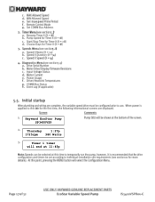
No bathers in Quick Clean mode. Input Voltage Within Range Motor Current 1.1A (0-13.0A) Power Usage 225W (0-2650W) Driver: 78C Heatsink: 67C Comm Bus Online (Addr: 1) Event log Press + to resume normal operation. press STOP/RESUME again to view Pump is stopped; SVRS inactive in water During Quick Clean
No bathers in Quick Clean mode. Input Voltage Within Range Motor Current 1.1A (0-13.0A) Power Usage 225W (0-2650W) Driver: 78C Heatsink: 67C Comm Bus Online (Addr: 1) Event log Press + to resume normal operation. press STOP/RESUME again to view Pump is stopped; SVRS inactive in water During Quick Clean
Technical Guide
Page 1
Variable Speed Pump and Drive Technical Guide © 2011 Hayward Pool Products Version 2 Drive FW 1.02 Interface FW 2.55 residential Interface FW 1.00 commercial
Variable Speed Pump and Drive Technical Guide © 2011 Hayward Pool Products Version 2 Drive FW 1.02 Interface FW 2.55 residential Interface FW 1.00 commercial

Technical Guide
Page 4
Existing Pools: When installing the EcoStar on a new pool, care should be taken to ensure proper pipe and equipment sizing to handle the maximum flow required (fig 1). Note: length of the ... 6fps * Refer to insure the maximum flow does not exceed the capacity of pipe (L) between pump suction port and first elbow or fitting should be at least 5 times pipe size. Installation - Plumbing New Pools: When installing the EcoStar on existing pools, care should be taken to equipment manuals for flow rates. 3" 184gpm...
Existing Pools: When installing the EcoStar on a new pool, care should be taken to ensure proper pipe and equipment sizing to handle the maximum flow required (fig 1). Note: length of the ... 6fps * Refer to insure the maximum flow does not exceed the capacity of pipe (L) between pump suction port and first elbow or fitting should be at least 5 times pipe size. Installation - Plumbing New Pools: When installing the EcoStar on existing pools, care should be taken to equipment manuals for flow rates. 3" 184gpm...

Technical Guide
Page 5
Figure 3 Figure 4 Page 3 Electrical Remove the electrical cover plate as shown below (fig 2, 3 & 4) Figure 2 Note: If power is removed from the pump, all settings will be protected for at least 5 years. Installation -
Figure 3 Figure 4 Page 3 Electrical Remove the electrical cover plate as shown below (fig 2, 3 & 4) Figure 2 Note: If power is removed from the pump, all settings will be protected for at least 5 years. Installation -

Technical Guide
Page 7
... Single Phase. 2. It is data connected to a Hayward/Goldline control, voltage needs to come directly from a breaker in the control, or in the case of an OnCommand, directly from the main or sub-panel and not from the filter pump relay. One for high voltage and the other for ... voltage data cable. Note: When connecting high voltage for an EcoStar that is below high voltage wires and should be determined by the NEC and local code requirements. Ground Wire Terminal. Figure 6 Conduit Connections There are two on the pump. Make sure the unit is both bonded and grounded Page ...
... Single Phase. 2. It is data connected to a Hayward/Goldline control, voltage needs to come directly from a breaker in the control, or in the case of an OnCommand, directly from the main or sub-panel and not from the filter pump relay. One for high voltage and the other for ... voltage data cable. Note: When connecting high voltage for an EcoStar that is below high voltage wires and should be determined by the NEC and local code requirements. Ground Wire Terminal. Figure 6 Conduit Connections There are two on the pump. Make sure the unit is both bonded and grounded Page ...

Technical Guide
Page 11
Attach the interface assembly to the mounting bracket with the data plug on the pump (fig 20). Figure 18 Figure 19 Figure 20 Figure 21 Page 9 Attach the six wires to note the color and corresponding number on the bottom of the bracket (fig 18). 8. Secure the wall mounting bracket and route the six wire data cable through the channel on the data plug as shown, taking care to the new data plug as you did with the two screws provided (fig 21). Install the plug into the interface assembly (fig 19). 9. Installation-Interface/Wall Mount 7.
Attach the interface assembly to the mounting bracket with the data plug on the pump (fig 20). Figure 18 Figure 19 Figure 20 Figure 21 Page 9 Attach the six wires to note the color and corresponding number on the bottom of the bracket (fig 18). 8. Secure the wall mounting bracket and route the six wire data cable through the channel on the data plug as shown, taking care to the new data plug as you did with the two screws provided (fig 21). Install the plug into the interface assembly (fig 19). 9. Installation-Interface/Wall Mount 7.

Technical Guide
Page 12
... and the 4 connector data plug from the filter pump relay. panel and not from the controller (fig 22). Wire 7 on the pump to 2 on the controller, 8 on the pump to 3 on the controller and 1 on 7 EcoStar is data connected to a Hayward/Goldline control, voltage needs to come directly from a ...breaker in the control, or in units 8 Mfg 5/19/11 1 going forward Figure 23 Pump Terminal Data Plugs ...
... and the 4 connector data plug from the filter pump relay. panel and not from the controller (fig 22). Wire 7 on the pump to 2 on the controller, 8 on the pump to 3 on the controller and 1 on 7 EcoStar is data connected to a Hayward/Goldline control, voltage needs to come directly from a ...breaker in the control, or in units 8 Mfg 5/19/11 1 going forward Figure 23 Pump Terminal Data Plugs ...

Technical Guide
Page 13
The "Load Out" side will feed the incoming high voltage for maximum voltage in the control box. Filter Pump Replay AUX Relay AUX Relay AUX Relay Fig 24 Page 11 Pump power (230 VAC) needs to be rated for the pump (fig 24). Installation-Relay Connected Controls (Non Hayward/Goldline compatible software & third party controls) 1. Cable used for data connections should be brought into the "line in" contacts on the Filter Pump Relay from a breaker in motor compartment.
The "Load Out" side will feed the incoming high voltage for maximum voltage in the control box. Filter Pump Replay AUX Relay AUX Relay AUX Relay Fig 24 Page 11 Pump power (230 VAC) needs to be rated for the pump (fig 24). Installation-Relay Connected Controls (Non Hayward/Goldline compatible software & third party controls) 1. Cable used for data connections should be brought into the "line in" contacts on the Filter Pump Relay from a breaker in motor compartment.

Technical Guide
Page 14
One side of the 24 VAC connection on the pump terminal needs to be wired to the Load side of 4. The other leg of the 24 VAC connection on each control relays as shown (fig 25). 25). Installation-Relay Connected Controls (Non Hayward/Goldline compatible software & third party controls) 2. 1, 3 and 5 from the pump terminal needs to be line side of the relays in series as shown (fig wired with 2, 4 & 6 on the pump terminal as shown (fig 25). the pump terminal needs to be wired to the 3. Filter Pump Replay AUX Relay AUX Relay AUX Relay Fig 25 Page 12
One side of the 24 VAC connection on the pump terminal needs to be wired to the Load side of 4. The other leg of the 24 VAC connection on each control relays as shown (fig 25). 25). Installation-Relay Connected Controls (Non Hayward/Goldline compatible software & third party controls) 2. 1, 3 and 5 from the pump terminal needs to be line side of the relays in series as shown (fig wired with 2, 4 & 6 on the pump terminal as shown (fig 25). the pump terminal needs to be wired to the 3. Filter Pump Replay AUX Relay AUX Relay AUX Relay Fig 25 Page 12

Technical Guide
Page 15
...Aux (1) Timer 1 Speed On Off Timer 2 Speed On On Fig 28 Page 13 Filter pump relay plus 2 aux relays allows control of aux relays used. Installation-Relay Connected Controls (Non Hayward/Goldline compatible software & third party controls) 5. As shown by the charts, the number ...of speeds available depends on the number of 4 speeds Filter Pump Relay 1st Aux (1) 2nd Aux (3) Timer 1 Speed On Off ...
...Aux (1) Timer 1 Speed On Off Timer 2 Speed On On Fig 28 Page 13 Filter pump relay plus 2 aux relays allows control of aux relays used. Installation-Relay Connected Controls (Non Hayward/Goldline compatible software & third party controls) 5. As shown by the charts, the number ...of speeds available depends on the number of 4 speeds Filter Pump Relay 1st Aux (1) 2nd Aux (3) Timer 1 Speed On Off ...

Technical Guide
Page 16
... 29). 2. Some switches have wiring for its internal wiring. Refer to the emergency switch (fig 29). Note: The emergency switch needs to 8 on the pump terminal needs to be wired to be wired to the e-switch for both NO and NC (normally Closed). When the switch is pressed the 24v... circuit is normally open (NO). One side of the 24 VAC on the pump terminal need to be a latching style that is completed and the pump will shut down operation. Installation-Remote Stop Switch 1. Remote stop switch purchased separately Fig 29 Page 14
... 29). 2. Some switches have wiring for its internal wiring. Refer to the emergency switch (fig 29). Note: The emergency switch needs to 8 on the pump terminal needs to be wired to be wired to the e-switch for both NO and NC (normally Closed). When the switch is pressed the 24v... circuit is normally open (NO). One side of the 24 VAC on the pump terminal need to be a latching style that is completed and the pump will shut down operation. Installation-Remote Stop Switch 1. Remote stop switch purchased separately Fig 29 Page 14

Technical Guide
Page 17
...between displays and to select parameters to run at a pre-determined speed for cleaning. It will blink when in the quick clean mode with pump (1 hour default timer). QUICK CLEAN Elevates the speed of time. Programming - The & buttons are used to max set speed for a certain ... change the parameters. LED will illuminate solid when there is an error condition. Page 15 CHECK SYSTEM LED LED will illuminate indicating the pump has stopped. TIMERS ACTIVE LED LED will resume normal operations. Places SVRS in a specific setup menu. User Interface PRESET SPEEDS 4 buttons ...
...between displays and to select parameters to run at a pre-determined speed for cleaning. It will blink when in the quick clean mode with pump (1 hour default timer). QUICK CLEAN Elevates the speed of time. Programming - The & buttons are used to max set speed for a certain ... change the parameters. LED will illuminate solid when there is an error condition. Page 15 CHECK SYSTEM LED LED will illuminate indicating the pump has stopped. TIMERS ACTIVE LED LED will resume normal operations. Places SVRS in a specific setup menu. User Interface PRESET SPEEDS 4 buttons ...
Technical Guide
Page 18
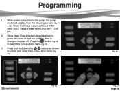
Since timer 1 has a factory default setting the pump will have default setting of 1750 RPM (50%), 7 days a week from 12:00 am - 11:45 pm. 2. Press the button (fig 32) to unlock and enter the Configuration menu (fig 33). Timer 1 will come on and run until the timer is supplied to the pump, the pump model will display, then the following screens (fig 31 & 32). When power is changed or set as shown to select the Configuration menu (fig 33). 3. Programming 1. Press and hold down the & buttons as off. Fig 31 Fig 32 Fig 33 Page 16
Since timer 1 has a factory default setting the pump will have default setting of 1750 RPM (50%), 7 days a week from 12:00 am - 11:45 pm. 2. Press the button (fig 32) to unlock and enter the Configuration menu (fig 33). Timer 1 will come on and run until the timer is supplied to the pump, the pump model will display, then the following screens (fig 31 & 32). When power is changed or set as shown to select the Configuration menu (fig 33). 3. Programming 1. Press and hold down the & buttons as off. Fig 31 Fig 32 Fig 33 Page 16

Technical Guide
Page 27
Note: All speed settings in Configuration. 1. Timer 1 will start and stop pump. Timer 1 can be changed as relays on control connected pumps. Press the button to run the pump if the data link fails on controller will be factory set to 1725 rpm (50%), 7 day operation from 12 am to the Max Settings set... speed be set as needed. . Compatible Software controller: No timer or speed settings necessary. Com bus address needs to be set. Programming-Timers Stand alone/Hayward Stand alone: Both times and speeds need to be set.
Note: All speed settings in Configuration. 1. Timer 1 will start and stop pump. Timer 1 can be changed as relays on control connected pumps. Press the button to run the pump if the data link fails on controller will be factory set to 1725 rpm (50%), 7 day operation from 12 am to the Max Settings set... speed be set as needed. . Compatible Software controller: No timer or speed settings necessary. Com bus address needs to be set. Programming-Timers Stand alone/Hayward Stand alone: Both times and speeds need to be set.
Technical Guide
Page 32
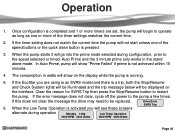
...settings matches the current time. 2. If the timer setting does not match the current time the pump will begin to the speed selected or timed. Once configuration is completed and 1 or more of... System lights will be replaced. 6. When the Low Temp Operation is activated you are set, the pump will not start unless one or more timers are using is an SVRS model and there is not ..., cycle off the power to restart the pump. Clear the reason for SVRS Trip then press the Stop/Resume button to the pump a few times. If the EcoStar you will be displayed on the display while...
...settings matches the current time. 2. If the timer setting does not match the current time the pump will begin to the speed selected or timed. Once configuration is completed and 1 or more of... System lights will be replaced. 6. When the Low Temp Operation is activated you are set, the pump will not start unless one or more timers are using is an SVRS model and there is not ..., cycle off the power to restart the pump. Clear the reason for SVRS Trip then press the Stop/Resume button to the pump a few times. If the EcoStar you will be displayed on the display while...

Technical Guide
Page 33
...adjusting speed will lock in the Speed Setup Menu. CHECK SYSTEM LED LED will illuminate solid when there is not running. Even if the pump is an error condition. LED will illuminate once the timers have been programmed. QUICK CLEAN Elevates the speed of the speed button will add...the „+‟ or‟-‟ key during a speed choice will resume normal operations. Pressed again the pump will raise or lower the speed. Each subsequent pressing of the pump to the speed and duration that was set speed for cleaning. Operation Display Screen Fig 62 STOP RESUME When ...
...adjusting speed will lock in the Speed Setup Menu. CHECK SYSTEM LED LED will illuminate solid when there is not running. Even if the pump is an error condition. LED will illuminate once the timers have been programmed. QUICK CLEAN Elevates the speed of the speed button will add...the „+‟ or‟-‟ key during a speed choice will resume normal operations. Pressed again the pump will raise or lower the speed. Each subsequent pressing of the pump to the speed and duration that was set speed for cleaning. Operation Display Screen Fig 62 STOP RESUME When ...

Technical Guide
Page 34
... are set to timer 8 speed at 3 pm. Page 32 Goes back to meet spa jet or any water feature requirement. Goes back to operate. Timer 8: Pump comes on at 6 am and goes off at 5:45 am Set to run the entire timing sequence at the low speed setting. 6 am... pump kicks into speed needed for solar operation. Timer 2: At 1 pm pump kicks into the speed needed for cleaner to timer 8 speed at 12 noon. Programming Scenarios Below is one possible Stand...
... are set to timer 8 speed at 3 pm. Page 32 Goes back to meet spa jet or any water feature requirement. Goes back to operate. Timer 8: Pump comes on at 6 am and goes off at 5:45 am Set to run the entire timing sequence at the low speed setting. 6 am... pump kicks into speed needed for solar operation. Timer 2: At 1 pm pump kicks into the speed needed for cleaner to timer 8 speed at 12 noon. Programming Scenarios Below is one possible Stand...

Technical Guide
Page 35
Disassembly/Assembly This guide will only cover the disassembly of the EcoStar is exactly like the standard TriStar pump. Wiring Compartment Cover Interface Assembly Variable Speed Drive Figure 63 Motor/Fan Shroud Motor Page 33 The wet end disassembly of the drive and motor area for this guide.
Disassembly/Assembly This guide will only cover the disassembly of the EcoStar is exactly like the standard TriStar pump. Wiring Compartment Cover Interface Assembly Variable Speed Drive Figure 63 Motor/Fan Shroud Motor Page 33 The wet end disassembly of the drive and motor area for this guide.

Technical Guide
Page 36
Figure 64 Figure 65 Page 34 Remove the screw as shown (fig 65). Disassembly/Assembly 1. Remove the wiring compartment cover as shown (fig 64). Shut down power to the pump by moving the breaker supplying power to the pump to the off position. 2.
Figure 64 Figure 65 Page 34 Remove the screw as shown (fig 65). Disassembly/Assembly 1. Remove the wiring compartment cover as shown (fig 64). Shut down power to the pump by moving the breaker supplying power to the pump to the off position. 2.


