
Technical Guide
Page 2
Table of Contents Safety Precautions Installation Programming Operation Programming Scenarios Disassembly/Assembly Password/Commercial Diagnostics/Troubleshooting Page 1 Page 2-14 Page 15-29 Page 30-31 Page 32 Page 33-38 Page 39-40 Page 41-48
Table of Contents Safety Precautions Installation Programming Operation Programming Scenarios Disassembly/Assembly Password/Commercial Diagnostics/Troubleshooting Page 1 Page 2-14 Page 15-29 Page 30-31 Page 32 Page 33-38 Page 39-40 Page 41-48

Technical Guide
Page 3
..., burn, and cause death or serious property damage. Provide a properly located electrical receptacle. Page 1 To reduce the risk of electric shock, see installation instructions and consult a professional electrician on the equipment. Also, contact a licensed electrician for information on drive or motor, turn off power supply to ... will increase risk for bonding requirements. Hazardous voltage can cause severe injury and/or death. This product should be installed and serviced only by a qualified professional. All electrical wiring MUST be in injury or death.
..., burn, and cause death or serious property damage. Provide a properly located electrical receptacle. Page 1 To reduce the risk of electric shock, see installation instructions and consult a professional electrician on the equipment. Also, contact a licensed electrician for information on drive or motor, turn off power supply to ... will increase risk for bonding requirements. Hazardous voltage can cause severe injury and/or death. This product should be installed and serviced only by a qualified professional. All electrical wiring MUST be in injury or death.

Technical Guide
Page 4
... the maximum flow required (fig 1). Note: length of the pipe and equipment* (fig 1). Plumbing New Pools: When installing the EcoStar on existing pools, care should be at least 5 times pipe size. Installation - Existing Pools: When installing the EcoStar on a new pool, care should be taken to insure the maximum flow does not exceed the capacity...
... the maximum flow required (fig 1). Note: length of the pipe and equipment* (fig 1). Plumbing New Pools: When installing the EcoStar on existing pools, care should be at least 5 times pipe size. Installation - Existing Pools: When installing the EcoStar on a new pool, care should be taken to insure the maximum flow does not exceed the capacity...

Technical Guide
Page 5
Figure 3 Figure 4 Page 3 Electrical Remove the electrical cover plate as shown below (fig 2, 3 & 4) Figure 2 Note: If power is removed from the pump, all settings will be protected for at least 5 years. Installation -
Figure 3 Figure 4 Page 3 Electrical Remove the electrical cover plate as shown below (fig 2, 3 & 4) Figure 2 Note: If power is removed from the pump, all settings will be protected for at least 5 years. Installation -
Technical Guide
Page 6
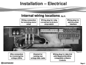
Electrical Internal wiring locations (fig 5) Wiring connection for incoming motor wires Wiring plug for relay connected controls & stop switch Wiring plug for wall mounted interface Wire connection for incoming line voltage (230v) Channel for running low voltage data cable Wiring plug for data link with Hayward/Goldline compatible software Controls Figure 5 Page 4 Installation -
Electrical Internal wiring locations (fig 5) Wiring connection for incoming motor wires Wiring plug for relay connected controls & stop switch Wiring plug for wall mounted interface Wire connection for incoming line voltage (230v) Channel for running low voltage data cable Wiring plug for data link with Hayward/Goldline compatible software Controls Figure 5 Page 4 Installation -

Technical Guide
Page 7
...NEC and local code requirements. Breaker, wire size would be connected first. One for high voltage and the other for an EcoStar that is data connected to a Hayward/Goldline control, voltage needs to come directly from a breaker in the control, or in the case of an OnCommand, ...directly from the main or sub-panel and not from the filter pump relay. It is both bonded and grounded Page 5 Figure 6 Conduit Connections There are two on the pump. Installation...
...NEC and local code requirements. Breaker, wire size would be connected first. One for high voltage and the other for an EcoStar that is data connected to a Hayward/Goldline control, voltage needs to come directly from a breaker in the control, or in the case of an OnCommand, ...directly from the main or sub-panel and not from the filter pump relay. It is both bonded and grounded Page 5 Figure 6 Conduit Connections There are two on the pump. Installation...

Technical Guide
Page 8
Remove the two screws as shown (fig 7, 9, 10 & 11) and re-secure with the two screws (fig 7). Reposition interface assembly as shown (fig 7). 2. Remove the interface assembly as shown (fig 8). 3. Figure 7 Figure 8 Figure 9 Figure 10 Figure 11 Page 6 Installation-Interface removal/positioning The interface assembly on the EcoStar can be configured in four different positions. 1.
Remove the two screws as shown (fig 7, 9, 10 & 11) and re-secure with the two screws (fig 7). Reposition interface assembly as shown (fig 7). 2. Remove the interface assembly as shown (fig 8). 3. Figure 7 Figure 8 Figure 9 Figure 10 Figure 11 Page 6 Installation-Interface removal/positioning The interface assembly on the EcoStar can be configured in four different positions. 1.

Technical Guide
Page 9
After removal of the interface assembly (Page 7) remove the plug connecting the drive to the interface assembly. Plug is included with the EcoStar and includes blank cover, mounting bracket and new terminal block for wall mount or control connection. 2. Figure 12 Figure 13 Figure 14 Page 7 Installation-Interface /Wall mount 1. Wall mount kit is permanently attached (fig 13), install the blank cover over the plug (fig 14). Maximum 500‟ for data cable used for connecting to the interface (fig 12). 3.
After removal of the interface assembly (Page 7) remove the plug connecting the drive to the interface assembly. Plug is included with the EcoStar and includes blank cover, mounting bracket and new terminal block for wall mount or control connection. 2. Figure 12 Figure 13 Figure 14 Page 7 Installation-Interface /Wall mount 1. Wall mount kit is permanently attached (fig 13), install the blank cover over the plug (fig 14). Maximum 500‟ for data cable used for connecting to the interface (fig 12). 3.
Technical Guide
Page 10
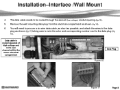
... corresponding number next to be routed through the second (low voltage) conduit opening (fig 15). 5. The data cable needs to the data plug (fig 15). Installation-Interface /Wall Mount 4.
... corresponding number next to be routed through the second (low voltage) conduit opening (fig 15). 5. The data cable needs to the data plug (fig 15). Installation-Interface /Wall Mount 4.

Technical Guide
Page 11
Installation-Interface/Wall Mount 7. Install the plug into the interface assembly (fig 19). 9. Attach the interface assembly to note the color and corresponding number on the data plug as you did with the two screws provided (fig 21). Attach the six wires to the new data plug as shown, taking care to the mounting bracket with the data plug on the bottom of the bracket (fig 18). 8. Figure 18 Figure 19 Figure 20 Figure 21 Page 9 Secure the wall mounting bracket and route the six wire data cable through the channel on the pump (fig 20).
Installation-Interface/Wall Mount 7. Install the plug into the interface assembly (fig 19). 9. Attach the interface assembly to note the color and corresponding number on the data plug as you did with the two screws provided (fig 21). Attach the six wires to the new data plug as shown, taking care to the mounting bracket with the data plug on the bottom of the bracket (fig 18). 8. Figure 18 Figure 19 Figure 20 Figure 21 Page 9 Secure the wall mounting bracket and route the six wire data cable through the channel on the pump (fig 20).

Technical Guide
Page 12
... or sub- Wire colors can be run through the second (data) conduit opening and channel (Page 8). 2. Control Data Plug Software versions necessary to operate the EcoStar Aqua Logic/Pro Logic/Aqua Plus v2.65 or higher OnCommand 1.00 or higher E-Command 4 (Original E-Command not compatible) v2.80 or higher 2 3 Figure 22... to point. Remove the two data plugs (COMBUS & DISPLAY) from the wiring compartment (fig 23) and the 4 connector data plug from the filter pump relay. Installation-Hayward/Goldline Controls (Compatible software shown below) 1.
... or sub- Wire colors can be run through the second (data) conduit opening and channel (Page 8). 2. Control Data Plug Software versions necessary to operate the EcoStar Aqua Logic/Pro Logic/Aqua Plus v2.65 or higher OnCommand 1.00 or higher E-Command 4 (Original E-Command not compatible) v2.80 or higher 2 3 Figure 22... to point. Remove the two data plugs (COMBUS & DISPLAY) from the wiring compartment (fig 23) and the 4 connector data plug from the filter pump relay. Installation-Hayward/Goldline Controls (Compatible software shown below) 1.

Technical Guide
Page 13
Cable used for data connections should be brought into the "line in" contacts on the Filter Pump Relay from a breaker in motor compartment. Installation-Relay Connected Controls (Non Hayward/Goldline compatible software & third party controls) 1. Filter Pump Replay AUX Relay AUX Relay AUX Relay Fig 24 Page 11 Pump power (230 VAC) needs to be rated for the pump (fig 24). The "Load Out" side will feed the incoming high voltage for maximum voltage in the control box.
Cable used for data connections should be brought into the "line in" contacts on the Filter Pump Relay from a breaker in motor compartment. Installation-Relay Connected Controls (Non Hayward/Goldline compatible software & third party controls) 1. Filter Pump Replay AUX Relay AUX Relay AUX Relay Fig 24 Page 11 Pump power (230 VAC) needs to be rated for the pump (fig 24). The "Load Out" side will feed the incoming high voltage for maximum voltage in the control box.

Technical Guide
Page 14
the pump terminal needs to be wired to the Load side of 4. One side of the 24 VAC connection on the pump terminal needs to be line side of the 24 VAC connection on the pump terminal as shown (fig 25). Installation-Relay Connected Controls (Non Hayward/Goldline compatible software & third party controls) 2. 1, 3 and 5 from the pump terminal needs to be wired to the 3. Filter Pump Replay AUX Relay AUX Relay AUX Relay Fig 25 Page 12 The other leg of the relays in series as shown (fig wired with 2, 4 & 6 on each control relays as shown (fig 25). 25).
the pump terminal needs to be wired to the Load side of 4. One side of the 24 VAC connection on the pump terminal needs to be line side of the 24 VAC connection on the pump terminal as shown (fig 25). Installation-Relay Connected Controls (Non Hayward/Goldline compatible software & third party controls) 2. 1, 3 and 5 from the pump terminal needs to be wired to the 3. Filter Pump Replay AUX Relay AUX Relay AUX Relay Fig 25 Page 12 The other leg of the relays in series as shown (fig wired with 2, 4 & 6 on each control relays as shown (fig 25). 25).

Technical Guide
Page 15
... 4 Speed On On On Fig 27 Note: The numbers in (blue) on each chart are the corresponding connecting points on the pump for each relay. Installation-Relay Connected Controls (Non Hayward/Goldline compatible software & third party controls) 5.
... 4 Speed On On On Fig 27 Note: The numbers in (blue) on each chart are the corresponding connecting points on the pump for each relay. Installation-Relay Connected Controls (Non Hayward/Goldline compatible software & third party controls) 5.

Technical Guide
Page 16
When the switch is pressed the 24v circuit is normally open (NO). Installation-Remote Stop Switch 1. One side of the 24 VAC on the pump terminal need to be wired to 8 on the pump terminal needs to the e-...
When the switch is pressed the 24v circuit is normally open (NO). Installation-Remote Stop Switch 1. One side of the 24 VAC on the pump terminal need to be wired to 8 on the pump terminal needs to the e-...

Technical Guide
Page 40
Note: The fan shown (fig 73) comes as shown (fig 76). Figure 75 Figure 76 Page 38 It should always be installed upside down. Square top section of shroud should also be noted that the fan shroud can be on each side of the motor assembly. Disassembly/Assembly 11. Remove the fan Shroud as part of the fan shroud as shown (fig 75). 12. Remove the two screws on the top section of motor.
Note: The fan shown (fig 73) comes as shown (fig 76). Figure 75 Figure 76 Page 38 It should always be installed upside down. Square top section of shroud should also be noted that the fan shroud can be on each side of the motor assembly. Disassembly/Assembly 11. Remove the fan Shroud as part of the fan shroud as shown (fig 75). 12. Remove the two screws on the top section of motor.

Technical Guide
Page 48
... breaker, replace drive. When it comes on the comm. Check input wiring and breaker. Install RS485 isolator, or new interface v2.55 rev. 1.1. The breaker is caused by frequency noise emitted from drive. EcoStar is connected to a GL/Hayward control. Disconnect the wires from the control. If the values are correct, replace the...
... breaker, replace drive. When it comes on the comm. Check input wiring and breaker. Install RS485 isolator, or new interface v2.55 rev. 1.1. The breaker is caused by frequency noise emitted from drive. EcoStar is connected to a GL/Hayward control. Disconnect the wires from the control. If the values are correct, replace the...


