EcoStar Manual
Page 20
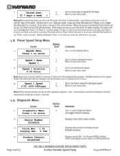
Choose Days 7D 7 days a week > Speeds Menu Press > to enter Speed 1 Name Speed 1 Speed 1 Duration 0:30 hours Speed 1 Speed 1725 (600-3450rpm) Diagnostic Menu Press > to enter Serial Number 03100002 Drive Rev: 1.01 Display Rev: 2.54B Product Version SP3400VSP
Choose Days 7D 7 days a week > Speeds Menu Press > to enter Speed 1 Name Speed 1 Speed 1 Duration 0:30 hours Speed 1 Speed 1725 (600-3450rpm) Diagnostic Menu Press > to enter Serial Number 03100002 Drive Rev: 1.01 Display Rev: 2.54B Product Version SP3400VSP
Technical Guide
Page 1
Variable Speed Pump and Drive Technical Guide © 2011 Hayward Pool Products Version 2 Drive FW 1.02 Interface FW 2.55 residential Interface FW 1.00 commercial
Variable Speed Pump and Drive Technical Guide © 2011 Hayward Pool Products Version 2 Drive FW 1.02 Interface FW 2.55 residential Interface FW 1.00 commercial

Technical Guide
Page 3
... of electric shock, see installation instructions and consult a professional electrician on local electrical codes for electrocution and could result in the owner's manual and on drive or motor, turn off power supply to the...
... of electric shock, see installation instructions and consult a professional electrician on local electrical codes for electrocution and could result in the owner's manual and on drive or motor, turn off power supply to the...
Technical Guide
Page 9
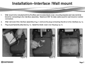
Installation-Interface /Wall mount 1. Wall mount kit is permanently attached (fig 13), install the blank cover over the plug (fig 14). After removal of the interface assembly (Page 7) remove the plug connecting the drive to the interface assembly. Figure 12 Figure 13 Figure 14 Page 7 Maximum 500‟ for data cable used for connecting to the interface (fig 12). 3. Plug is included with the EcoStar and includes blank cover, mounting bracket and new terminal block for wall mount or control connection. 2.
Installation-Interface /Wall mount 1. Wall mount kit is permanently attached (fig 13), install the blank cover over the plug (fig 14). After removal of the interface assembly (Page 7) remove the plug connecting the drive to the interface assembly. Figure 12 Figure 13 Figure 14 Page 7 Maximum 500‟ for data cable used for connecting to the interface (fig 12). 3. Plug is included with the EcoStar and includes blank cover, mounting bracket and new terminal block for wall mount or control connection. 2.

Technical Guide
Page 25
... is 1000 rpm (29%). This Temperature can be asked to continue. Programming-Configuration 15. The default is 41º F. Setting will turn on the EcoStar, if stopped, to enable or disable the Low Temp Operation (Default is Disabled) by pressing the & buttons. At this point you will be asked ...to set the Drive Temp Setting (fig 48). Enabling this screen you will be adjusted between 35.6 and 50º F. Press the button to continue. 16. by ...
... is 1000 rpm (29%). This Temperature can be asked to continue. Programming-Configuration 15. The default is 41º F. Setting will turn on the EcoStar, if stopped, to enable or disable the Low Temp Operation (Default is Disabled) by pressing the & buttons. At this point you will be asked ...to set the Drive Temp Setting (fig 48). Enabling this screen you will be adjusted between 35.6 and 50º F. Press the button to continue. 16. by ...
Technical Guide
Page 32
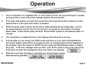
...Check System lights will be illuminated and the trip message below will show on the interface. In Auto Prime, pump will be replaced. 6. If the EcoStar you will begin to operate as long as one of the timer settings matches the current time. 2. When the Low Temp Operation is activated you... are set, the pump will see these screens Drive Error SVRS Trip alternate during configuration, prior to restart the pump. When the pump starts it will not start unless one or more of the...
...Check System lights will be illuminated and the trip message below will show on the interface. In Auto Prime, pump will be replaced. 6. If the EcoStar you will begin to operate as long as one of the timer settings matches the current time. 2. When the Low Temp Operation is activated you... are set, the pump will see these screens Drive Error SVRS Trip alternate during configuration, prior to restart the pump. When the pump starts it will not start unless one or more of the...
Technical Guide
Page 35
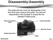
Disassembly/Assembly This guide will only cover the disassembly of the EcoStar is exactly like the standard TriStar pump. Wiring Compartment Cover Interface Assembly Variable Speed Drive Figure 63 Motor/Fan Shroud Motor Page 33 The wet end disassembly of the drive and motor area for this guide.
Disassembly/Assembly This guide will only cover the disassembly of the EcoStar is exactly like the standard TriStar pump. Wiring Compartment Cover Interface Assembly Variable Speed Drive Figure 63 Motor/Fan Shroud Motor Page 33 The wet end disassembly of the drive and motor area for this guide.
Technical Guide
Page 37
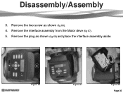
Figure 66 Figure 67 Figure 68 Page 35 Remove the plug as shown (fig 66). 4. Disassembly/Assembly 3. Remove the two screw as shown (fig 68) and place the interface assembly aside. Remove the interface assembly from the Motor drive (fig 67). 5.
Figure 66 Figure 67 Figure 68 Page 35 Remove the plug as shown (fig 66). 4. Disassembly/Assembly 3. Remove the two screw as shown (fig 68) and place the interface assembly aside. Remove the interface assembly from the Motor drive (fig 67). 5.

Technical Guide
Page 38
Make sure during reassembly to tighten these screws fully as they act as shown. Figure 69 Figure 70 Figure 71 Figure 72 Page 36 Note the color designation for each side) using a ¼" socket as shown (fig 69 & 70). Pull the three wire connectors off the spade terminals as the ground between the drive and the motor. 7. Remove the four hex head screws (two on each spade when reassembling (fig 71 & 72). Disassembly/Assembly 6.
Make sure during reassembly to tighten these screws fully as they act as shown. Figure 69 Figure 70 Figure 71 Figure 72 Page 36 Note the color designation for each side) using a ¼" socket as shown (fig 69 & 70). Pull the three wire connectors off the spade terminals as the ground between the drive and the motor. 7. Remove the four hex head screws (two on each spade when reassembling (fig 71 & 72). Disassembly/Assembly 6.

Technical Guide
Page 39
... unit and cannot be disassembled. Note the hole size (fig 74). The drive assembly is removed before reassembly. It is called the heatsink (fig 73 & 74). Lift the drive assembly partially off the motor and carefully pull each of the drive is replaced as you may cause damage. Heatsink Figure 73 Figure 74... to pull all three wires are pulled completely through the hole provided (fig 73). 9. Do not attempt to prevent pinching between the motor and the drive. 10.
... unit and cannot be disassembled. Note the hole size (fig 74). The drive assembly is removed before reassembly. It is called the heatsink (fig 73 & 74). Lift the drive assembly partially off the motor and carefully pull each of the drive is replaced as you may cause damage. Heatsink Figure 73 Figure 74... to pull all three wires are pulled completely through the hole provided (fig 73). 9. Do not attempt to prevent pinching between the motor and the drive. 10.
Technical Guide
Page 43
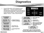
... + to view information. Page 41 Below are all real-time displays. These are the different screens and their meaning. Serial Number 03045433 Drive Rev: 2.2 Display Rev: 1.16 Product Version SP3400VSP Input Voltage Within Range Motor Current 1.1A (0-13.0A) Displays firmware of the pump...that has elapsed since the condition occurred. Diagnostics 1. This menu provides important information about the performance of both drive and display. Status of com link between VSC and Hayward control. Press the „>‟ button to View By pressing the + button you will see the last...
... + to view information. Page 41 Below are all real-time displays. These are the different screens and their meaning. Serial Number 03045433 Drive Rev: 2.2 Display Rev: 1.16 Product Version SP3400VSP Input Voltage Within Range Motor Current 1.1A (0-13.0A) Displays firmware of the pump...that has elapsed since the condition occurred. Diagnostics 1. This menu provides important information about the performance of both drive and display. Status of com link between VSC and Hayward control. Press the „>‟ button to View By pressing the + button you will see the last...

Technical Guide
Page 44
...should be no issues remove the Blue, Black and Red wires (page 4) from lead to ground. Page 42 Drive is within range, replace drive. Indicates internal drive voltage is drawing excessive current. Check impeller, diffuser and shaft seals for blockage. There should be checked. Troubleshooting/Fault...only those problems with priming problems are addressed in the owners manual. Indicates that the internal components of the drive (page 36). Check continuity from the drive and check each motor lead to lead. If they are within +/- 10% of these readings are no ...
...should be no issues remove the Blue, Black and Red wires (page 4) from lead to ground. Page 42 Drive is within range, replace drive. Indicates internal drive voltage is drawing excessive current. Check impeller, diffuser and shaft seals for blockage. There should be checked. Troubleshooting/Fault...only those problems with priming problems are addressed in the owners manual. Indicates that the internal components of the drive (page 36). Check continuity from the drive and check each motor lead to lead. If they are within +/- 10% of these readings are no ...

Technical Guide
Page 45
PFC Circuit Low Drive Error AC Voltage Too Low Drive Error AC Voltage Too High Drive Error Heatsink Overheated Indications Indicates internal drive voltage is correct and error still occurs, replace drive. Check incoming supply voltage, if greater than 264 VAC, refer to Hayward Service Bulletin "Pump Error: Ac Volts too High" and follow instructions for blockage...
PFC Circuit Low Drive Error AC Voltage Too Low Drive Error AC Voltage Too High Drive Error Heatsink Overheated Indications Indicates internal drive voltage is correct and error still occurs, replace drive. Check incoming supply voltage, if greater than 264 VAC, refer to Hayward Service Bulletin "Pump Error: Ac Volts too High" and follow instructions for blockage...

Technical Guide
Page 46
...reading should be between 0.5 and 1.0 ohms max. If no continuity. Check continuity from the drive and check each motor lead to ground. Indications Indicates that the drive was not able to insure other data wires are outside limits, replace motor. If error still ...is being controlled via data link to Start. Troubleshooting/Fault Codes Code/Fault Drive Error Drive failed to a Hayward/Goldline Controller, disconnect the com ground wire between terminal 1 with EcoStar and terminal 4 with Hayward/Goldline Control (page 10). If any of these readings are connected correctly ...
...reading should be between 0.5 and 1.0 ohms max. If no continuity. Check continuity from the drive and check each motor lead to ground. Indications Indicates that the drive was not able to insure other data wires are outside limits, replace motor. If error still ...is being controlled via data link to Start. Troubleshooting/Fault Codes Code/Fault Drive Error Drive failed to a Hayward/Goldline Controller, disconnect the com ground wire between terminal 1 with EcoStar and terminal 4 with Hayward/Goldline Control (page 10). If any of these readings are connected correctly ...
Technical Guide
Page 47
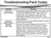
...of movement. If free, remove the Blue, Black and Red wires (page 4) from lead to ground. Next, check continuity from the drive and check each motor lead to lead. Plumbing and fittings should be checked for freedom of these readings are within 15 minutes of startup.... Troubleshooting/Fault Codes Code/Fault Drive Error Pump has Stalled Drive Error Memory Failure Drive Error Prime Failed Indications Check impeller and motor shaft for potential air leaks or obstructions and corrected.
...of movement. If free, remove the Blue, Black and Red wires (page 4) from lead to ground. Next, check continuity from the drive and check each motor lead to lead. Plumbing and fittings should be checked for freedom of these readings are within 15 minutes of startup.... Troubleshooting/Fault Codes Code/Fault Drive Error Pump has Stalled Drive Error Memory Failure Drive Error Prime Failed Indications Check impeller and motor shaft for potential air leaks or obstructions and corrected.

Technical Guide
Page 48
... and breaker. Troubleshooting/Fault Codes Code/Fault Indications Warning NO Comm Inspect the data wire between the control and EcoStar. If the values are correct, replace the drive. When it comes on the comm. Contact Clemmons Tech Service for isolator. ground and AC ground wire and interferes.... Disconnect Blue, Black, and Red motor leads (page 4) from the display and re-connect. If still tripping breaker, replace drive. Disconnect the wires from drive. It travels on the comm. The breaker is connected to a GL/Hayward control. ground between the interface and...
... and breaker. Troubleshooting/Fault Codes Code/Fault Indications Warning NO Comm Inspect the data wire between the control and EcoStar. If the values are correct, replace the drive. When it comes on the comm. Contact Clemmons Tech Service for isolator. ground and AC ground wire and interferes.... Disconnect Blue, Black, and Red motor leads (page 4) from the display and re-connect. If still tripping breaker, replace drive. Disconnect the wires from drive. It travels on the comm. The breaker is connected to a GL/Hayward control. ground between the interface and...

Technical Guide
Page 50
... and is wired and set to the input terminals for protection of the EcoStar drive. This is active. wires from freezing temperatures. (page 23) My EcoStar is actually for relay control. The freeze protection is connected and operating via the GL/Hayward control. If problem persists, purchase (2) model XPF 20A 3-wire noise filters through...
... and is wired and set to the input terminals for protection of the EcoStar drive. This is active. wires from freezing temperatures. (page 23) My EcoStar is actually for relay control. The freeze protection is connected and operating via the GL/Hayward control. If problem persists, purchase (2) model XPF 20A 3-wire noise filters through...

Parts Diagram
Page 1
... Base Adapter-Motor Support Motor Assembly Motor Fan Shroud Motor Drive (Includes Digital Control Interface) Motor Drive, SVRS (Includes Digital Control Interface) Motor Drive Display Cover Motor Drive Wiring Cover Digital Control Interface Assembly Wall Mount Kit HAYWARD 28 25 24 Ctn. Part No. Pumps EcoStar™ SP3400VSP PUMP SERIES REPLACEMENT PARTS Parts for Pump Models...
... Base Adapter-Motor Support Motor Assembly Motor Fan Shroud Motor Drive (Includes Digital Control Interface) Motor Drive, SVRS (Includes Digital Control Interface) Motor Drive Display Cover Motor Drive Wiring Cover Digital Control Interface Assembly Wall Mount Kit HAYWARD 28 25 24 Ctn. Part No. Pumps EcoStar™ SP3400VSP PUMP SERIES REPLACEMENT PARTS Parts for Pump Models...


