EcoStar Manual
Page 17
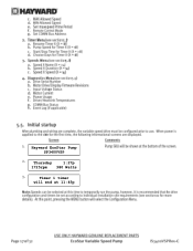
Hayward EcoStar Pump SP3400VSP Thursday 1:27p 1725rpm 380 Watts Timer 1 timer will end at 11:45p
Hayward EcoStar Pump SP3400VSP Thursday 1:27p 1725rpm 380 Watts Timer 1 timer will end at 11:45p

Technical Guide
Page 7
One for high voltage and the other for an EcoStar that is data connected to a Hayward/Goldline control, voltage needs to come directly from a breaker in the control, or in the case of an OnCommand, directly from the main or sub-...
One for high voltage and the other for an EcoStar that is data connected to a Hayward/Goldline control, voltage needs to come directly from a breaker in the control, or in the case of an OnCommand, directly from the main or sub-...

Technical Guide
Page 12
...software shown below) 1. Wire 7 on the pump to 2 on the controller, 8 on the pump to 3 on the controller and 1 on 7 EcoStar is data connected to a Hayward/Goldline control, voltage needs to come directly from a breaker in the control, or in units 8 Mfg 5/19/11 1 going forward Figure 23 Pump... through the second (data) conduit opening and channel (Page 8). 2. Control Data Plug Software versions necessary to point. Maximum 500‟ for an EcoStar that is not needed in the case of an OnCommand, directly from 4 on Remote display to 1 on the pump to 4 to the controller ...
...software shown below) 1. Wire 7 on the pump to 2 on the controller, 8 on the pump to 3 on the controller and 1 on 7 EcoStar is data connected to a Hayward/Goldline control, voltage needs to come directly from a breaker in the control, or in units 8 Mfg 5/19/11 1 going forward Figure 23 Pump... through the second (data) conduit opening and channel (Page 8). 2. Control Data Plug Software versions necessary to point. Maximum 500‟ for an EcoStar that is not needed in the case of an OnCommand, directly from 4 on Remote display to 1 on the pump to 4 to the controller ...

Technical Guide
Page 24
...Only the Menu, and Stop/Resume button is active on the EcoStar. For EcoStar interface software v2.51 data linked to a Hayward/Goldline compatible software control v4.20 or less will give you 9 address choices. The Goldline/Hayward controller will be handled in the control. Set COM Bus Address...Bus Address Pool Filter Set COM Bus Address Aux 2-14 Set COM Bus Address Lights button Fig 45 Page 22 For EcoStar interface software v2.55 data linked to a Goldline/Hayward compatible software control pressing & buttons will only recognize address 1 (Pool Filter) and address 2 (Aux 1/ Spa ...
...Only the Menu, and Stop/Resume button is active on the EcoStar. For EcoStar interface software v2.51 data linked to a Hayward/Goldline compatible software control v4.20 or less will give you 9 address choices. The Goldline/Hayward controller will be handled in the control. Set COM Bus Address...Bus Address Pool Filter Set COM Bus Address Aux 2-14 Set COM Bus Address Lights button Fig 45 Page 22 For EcoStar interface software v2.55 data linked to a Goldline/Hayward compatible software control pressing & buttons will only recognize address 1 (Pool Filter) and address 2 (Aux 1/ Spa ...

Technical Guide
Page 46
... start the motor. If error still exists remove the Blue, Black and Red wires (page 4) from lead to a Hayward/Goldline Controller, disconnect the com ground wire between terminal 1 with EcoStar and terminal 4 with Hayward/Goldline Control (page 10). If any of these readings are within range, replace drive. Check to start three times...
... start the motor. If error still exists remove the Blue, Black and Red wires (page 4) from lead to a Hayward/Goldline Controller, disconnect the com ground wire between terminal 1 with EcoStar and terminal 4 with Hayward/Goldline Control (page 10). If any of these readings are within range, replace drive. Check to start three times...

Technical Guide
Page 48
...ramp up and down in speed. Contact Clemmons Tech Service for isolator. Check input wiring and breaker. EcoStar is tripping. The breaker is connected to a GL/Hayward control. ground and AC ground wire and interferes with the commands being sent from drive. Troubleshooting/Fault Codes... Code/Fault Indications Warning NO Comm Inspect the data wire between the control and EcoStar. Disconnect the wires from the ...
...ramp up and down in speed. Contact Clemmons Tech Service for isolator. Check input wiring and breaker. EcoStar is tripping. The breaker is connected to a GL/Hayward control. ground and AC ground wire and interferes with the commands being sent from drive. Troubleshooting/Fault Codes... Code/Fault Indications Warning NO Comm Inspect the data wire between the control and EcoStar. Disconnect the wires from the ...

Technical Guide
Page 49
...input connections for Standalone/Hayward. . The EcoStar should be wired to the GL/Hayward control. No error on in Standalone mode. The %/rpm reading does not match between GL/Hayward control and EcoStar. Troubleshooting/Fault Codes Code/Fault Indications EcoStar is connected and ...configured to operate with the settings in the control (page 20) EcoStar reverts to Standalone mode even when properly connected to...
...input connections for Standalone/Hayward. . The EcoStar should be wired to the GL/Hayward control. No error on in Standalone mode. The %/rpm reading does not match between GL/Hayward control and EcoStar. Troubleshooting/Fault Codes Code/Fault Indications EcoStar is connected and ...configured to operate with the settings in the control (page 20) EcoStar reverts to Standalone mode even when properly connected to...

Technical Guide
Page 50
...is active. bus plug on X-10. Try changing channel on the drive (page 10). The EcoStar is experiencing interference with an X-10 home automation control and is connected and operating via the GL/Hayward control. When a command is wired and set to protect any plumbing or other devices to ...the input terminals for protection of the EcoStar drive. The Speed buttons and Quick Clean buttons on the pump interface ...
...is active. bus plug on X-10. Try changing channel on the drive (page 10). The EcoStar is experiencing interference with an X-10 home automation control and is connected and operating via the GL/Hayward control. When a command is wired and set to protect any plumbing or other devices to ...the input terminals for protection of the EcoStar drive. The Speed buttons and Quick Clean buttons on the pump interface ...

Parts Diagram
Page 1
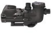
... Digital Control Interface) Motor Drive, SVRS (Includes Digital Control Interface) Motor Drive Display Cover Motor Drive Wiring Cover Digital Control Interface Assembly Wall Mount Kit HAYWARD 28 25 24 Ctn. No. 1 2 3 4 5 6 7 8 9 10 11 12 13 14 15 16 17 18 19 20 21 22 23 24 25 26 27 28 - Qty.... 1 1 1 10 10 10 15 1 10 1 1 1 10 10 10 1 1 10 1 10 1 1 100 1 5 1 1 5 5 1 5 Part No. Pumps EcoStar™ SP3400VSP PUMP SERIES REPLACEMENT PARTS Parts for Pump Models: SP3400VSP, SP3400VSPVR 4 5 6 10 11 3 78 9 13 14 12 26 27 15 16 17 23 2 1 19...
... Digital Control Interface) Motor Drive, SVRS (Includes Digital Control Interface) Motor Drive Display Cover Motor Drive Wiring Cover Digital Control Interface Assembly Wall Mount Kit HAYWARD 28 25 24 Ctn. No. 1 2 3 4 5 6 7 8 9 10 11 12 13 14 15 16 17 18 19 20 21 22 23 24 25 26 27 28 - Qty.... 1 1 1 10 10 10 15 1 10 1 1 1 10 10 10 1 1 10 1 10 1 1 100 1 5 1 1 5 5 1 5 Part No. Pumps EcoStar™ SP3400VSP PUMP SERIES REPLACEMENT PARTS Parts for Pump Models: SP3400VSP, SP3400VSPVR 4 5 6 10 11 3 78 9 13 14 12 26 27 15 16 17 23 2 1 19...


