Hayward EcoStar Support Question
Hayward EcoStar Support Question
Find answers below for this question about Hayward EcoStar.Need a Hayward EcoStar manual? We have 3 online manuals for this item!
Question posted by mkfj on June 28th, 2012
Turning Hayward Ecostar Off And On
when i push the on -off button it does not turn off. do i need to hold the button down or push it together with another button?
Current Answers
Related Hayward EcoStar Manual Pages
EcoStar Manual - Page 17
Hayward EcoStar Pump SP3400VSP
Thursday
1:27p
1725rpm 380 Watts
Timer 1 timer will end at 11:45p
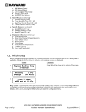
EcoStar Manual - Page 18

to adjust, > go to enter
Use + / - Configuration Menu Locked
Configuration Menu press > to next item Time: Th 1:27PM
+ change or > skip
Set Day and Time Thursday 1:27p
Speed Selection rpm
MAX allowed speed 3450 (600-3450rpm)
MIN allowed speed 600 (600-3450rpm)
Set max-speed Prime Period: Auto Sense
Remote Control Mode Standalone/Hayward
Set COMM Bus Address Pool Filter
Technical Guide - Page 1
Variable Speed Pump and Drive Technical Guide
© 2011 Hayward Pool Products
Version 2 Drive FW 1.02 Interface FW 2.55 residential Interface FW 1.00 commercial
Technical Guide - Page 3

...of electric shock, see installation instructions and consult a professional electrician on drive or motor, turn off power supply to the drive.
Failure to bond drive to follow all ... and the National Electric Code (NEC).
Provide a properly located electrical receptacle. Failure to pool structure will increase risk for electrocution and could result in the owner's manual and on...
Technical Guide - Page 4

...
38gpm 6fps
63gpm 6fps
89gpm 6fps
* Refer to handle the maximum flow required (fig 1). Existing Pools: When installing the EcoStar on a new pool, care should be at least 5 times pipe size. Plumbing
New Pools:
When installing the EcoStar on existing pools, care should be taken to ensure proper pipe and equipment sizing to equipment manuals for...
Technical Guide - Page 7

...). Figure 6
Conduit Connections
There are two on the pump. Voltage: 230 VAC, 60Hz, Single Phase. 2. Bonding Lug
8 AWG (6 AWG for an EcoStar that is data connected to a Hayward/Goldline control, voltage needs to come directly from a breaker in the control, or in the case of an OnCommand, directly from the main or sub...
Technical Guide - Page 8

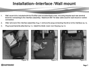
Installation-Interface removal/positioning
The interface assembly on the EcoStar can be configured in
four different positions.
1. Figure 7
Figure 8
Figure 9
Figure 10
Figure 11 Page 6 Remove the interface assembly as shown (fig 7, 9, 10 & 11) and re-secure with the two screws
(fig 7). Reposition interface assembly as shown (fig 8).
3. Remove the two screws as shown (fig 7).
2.
Technical Guide - Page 9
Plug is included with the EcoStar and includes blank cover, mounting bracket and new terminal block for wall mount or control connection.
2. Figure 12
Figure 13
Figure 14 Page 7 After removal ...
Technical Guide - Page 12

...conduit opening and channel (Page 8).
2.
Maximum 500‟ for an EcoStar that is not
needed in the case of an OnCommand, directly from a breaker in the ... 3 on the controller and 1 on
7
EcoStar is data connected to a Hayward/Goldline control, voltage
needs to
the controller as they match point
to point. Installation-Hayward/Goldline Controls
(Compatible software shown below)
1. ...
Technical Guide - Page 24

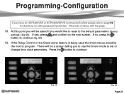
...(Pool Filter) and address 2 (Aux 1/ Spa Filter). Note: In the Hayward/Goldline compatible software mode the timers do not need to individual relays/Auxiliaries (fig 45).
For EcoStar interface software v2.51 data linked to continue.
14. Press the button to a Goldline/Hayward compatible software control pressing & buttons will only recognize address 1 (Pool Filter) and address 2 (Dual Spa...
Technical Guide - Page 25

...Default is Disabled) by pressing the & buttons.(fig 46).
Press the button to continue.
17. Press the button to continue.
16. by pressing the & buttons. Press the button to protect the drive . This speed ... asked to set the Drive Temp Setting (fig 48). Enabling this point you will turn on the EcoStar, if stopped, to continue. If the Low Temp Operation is 41º F. Default is...
Technical Guide - Page 26
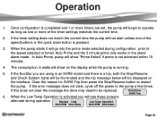
... 49). There will be asked if you would be a screen telling you have an HCP3400VSP or HCP3400VSPVR commercial EcoStar please refer to page 39 for directions on the next screen. At this page.
18. If no, press the button to continue. If yes, press and confirm on setting password protection.
Press the...
Technical Guide - Page 32
... and the trip message below will be replaced. 6. If the EcoStar you are set, the pump will go into the prime mode selected...If this does not clear the message the drive may need to restart
the pump. When the Low Temp Operation is pressed.
.../Resume button to be displayed on the display while the pump is completed and 1 or more of the speed buttons or the quick clean button is activated...
Technical Guide - Page 35
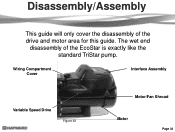
Disassembly/Assembly
This guide will only cover the disassembly of the EcoStar is exactly like the standard TriStar pump. The wet end
disassembly of the drive and motor area for this guide. Wiring Compartment Cover
Interface Assembly
Variable Speed Drive
Figure 63
Motor/Fan Shroud
Motor
Page 33
Technical Guide - Page 41

... and HCP3400VSPVR
Figure 79 Page 39 If you have a commercial EcoStar you can enable or disable the Password Protection feature by pressing the & button. If you enable this feature and the timeout has elapsed the... will see this point (fig 78) you will be prompted to 3 hrs by pressing the & button. At this point (fig 79) you can set . At this point you will be prompted to...
Technical Guide - Page 46

...reading should be between 0.5 and 1.0 ohms max. Indications
Indicates that the drive was not able to a Hayward/Goldline Controller, disconnect the com ground wire between interface and drive.
If any of these readings are connected... remove all (0) check connection between terminal 1 with EcoStar and terminal 4 with Hayward/Goldline Control (page 10).
Check to be sure motor shaft...
Technical Guide - Page 48

...Pool bridge comm"
This indicates interference on , the
pump will ramp up and down in speed. Install RS485 isolator, or new interface v2.55 rev. 1.1.
Page 46 ground and AC ground wire and interferes with the commands being sent from drive. Check input wiring and breaker.
EcoStar...wire between the control and EcoStar. This is connected to a GL/Hayward control. It travels on the...
Technical Guide - Page 49

... the maximum (3450rpm/100%) so as to not interfere with a GL/Hayward control.
Be sure they are made to
the GL/Hayward control. Page 47 Control reads "Pool bridge comm." Check comm. bus connection and NOT the input connections for Standalone/Hayward. . Be sure EcoStar is configured for relay control (page 10) .
Check the settings...
Technical Guide - Page 50

... wired and set to operate via the GL/Hayward control. When the control is operating the EcoStar, the Speed buttons and the Quick Clean button is sent to the input terminals for protection of the EcoStar drive.
When a command is inactive.
Only the Stop/Resume and
Menu button is actually for relay control.
If problem persists...
Parts Diagram - Page 1

... (Includes Digital Control Interface) Motor Drive Display Cover Motor Drive Wiring Cover Digital Control Interface Assembly Wall Mount Kit
HAYWARD
28
25
24
Ctn.
Qty. 1 1 1 10 10 10 15 1 10 1 1 1 10 10 ..., Lock Ring, O-Ring) Strainer Cover Kit (Biguanide Sanitizer Applications Only; Pumps
EcoStar™
SP3400VSP PUMP SERIES REPLACEMENT PARTS
Parts for Pump Models: SP3400VSP, SP3400VSPVR
4...
Similar Questions

How To Fix Ecostar Comm Bus Offline & Pro Logic Vsp Comm Error?
I cannot get my Hayward Pro Logic board to communicate with my Hayward Ecostar VSP pump. The pump sa...
I cannot get my Hayward Pro Logic board to communicate with my Hayward Ecostar VSP pump. The pump sa...
(Posted by m72422 7 years ago)


Swimming Pool Dome Sand Filter/how Much Sand Is Needed
(Posted by jespradap 10 years ago)
Dual Pool Spa System But The Settings Menu Doesn't Show Pool Heater Only Spa Hea
(Posted by Anonymous-39619 12 years ago)