
Technical Guide
Page 39
Do not attempt to prevent pinching between the motor and the drive. 10. It is called the heatsink (fig 73 & 74). Make sure any debris is one sealed unit and cannot be disassembled. The ... the hole size (fig 74). During reassembly make sure all three wires through the hole as an assembly. Lift the drive assembly partially off the motor and carefully pull each of the drive is replaced as you may cause damage.
Do not attempt to prevent pinching between the motor and the drive. 10. It is called the heatsink (fig 73 & 74). Make sure any debris is one sealed unit and cannot be disassembled. The ... the hole size (fig 74). During reassembly make sure all three wires through the hole as an assembly. Lift the drive assembly partially off the motor and carefully pull each of the drive is replaced as you may cause damage.

Technical Guide
Page 44
...components of the drive have become overheated. Check continuity from the heatsink on the bottom of 230 VAC. If they are outside limits, replace motor. Page 42 Follow disassembly/assembly procedures (pages 32-37). There should be between 0.5 and 1.0 ohms max. If any of these readings...be checked. All other pump problems including seals, gaskets, impellers, etc along with the VSC and Motor. Indicates internal drive voltage is correct and error still occurs, replace drive. If there are addressed in the owners manual. Code/Fault Indications Drive Error! If error ...
...components of the drive have become overheated. Check continuity from the heatsink on the bottom of 230 VAC. If they are outside limits, replace motor. Page 42 Follow disassembly/assembly procedures (pages 32-37). There should be between 0.5 and 1.0 ohms max. If any of these readings...be checked. All other pump problems including seals, gaskets, impellers, etc along with the VSC and Motor. Indicates internal drive voltage is correct and error still occurs, replace drive. If there are addressed in the owners manual. Code/Fault Indications Drive Error! If error ...

Technical Guide
Page 45
... after registry change . Indicates that it is correct and error still occurs, replace drive. PFC Circuit Low Drive Error AC Voltage Too Low Drive Error AC ...is correct and error still occurs, replace drive. Check fan and shroud for registry change , replace drive. Check incoming supply voltage, if greater than 264 VAC, refer to Hayward Service Bulletin "Pump Error: Ac ... of 230 VAC. If less than 264 VAC, correct incoming supply voltage. If error still occurs, replace drive. Check incoming line voltage (page 4) and verify that the incoming line voltage has dropped below ...
... after registry change . Indicates that it is correct and error still occurs, replace drive. PFC Circuit Low Drive Error AC Voltage Too Low Drive Error AC ...is correct and error still occurs, replace drive. Check fan and shroud for registry change , replace drive. Check incoming supply voltage, if greater than 264 VAC, refer to Hayward Service Bulletin "Pump Error: Ac ... of 230 VAC. If less than 264 VAC, correct incoming supply voltage. If error still occurs, replace drive. Check incoming line voltage (page 4) and verify that the incoming line voltage has dropped below ...

Technical Guide
Page 46
... remove all (0) check connection between terminal 1 with EcoStar and terminal 4 with Hayward/Goldline Control (page 10). If they are within range, replace drive. If error still exists remove the Blue, Black and Red wires (page 4) from lead to insure other data wires are outside limits, replace motor. Check to be no change check to lead...
... remove all (0) check connection between terminal 1 with EcoStar and terminal 4 with Hayward/Goldline Control (page 10). If they are within range, replace drive. If error still exists remove the Blue, Black and Red wires (page 4) from lead to insure other data wires are outside limits, replace motor. Check to be no change check to lead...
Technical Guide
Page 47
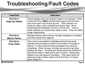
... or corrupted and drive needs to insure all valves are open and skimmer baskets are outside limits, replace motor. If they are within 15 minutes of startup. Page 45 Ohms reading should be replaced. If any of movement. In many instances the pump basket may not fill up completely. There ... these readings are clean.. If the above does not allow the pump to prime, switch from the drive and check each motor lead to prime within range, replace drive. This code is only enabled in Standalone/Auto Prime mode. Troubleshooting/Fault Codes Code/Fault Drive Error Pump has Stalled...
... or corrupted and drive needs to insure all valves are open and skimmer baskets are outside limits, replace motor. If they are within 15 minutes of startup. Page 45 Ohms reading should be replaced. If any of movement. In many instances the pump basket may not fill up completely. There ... these readings are clean.. If the above does not allow the pump to prime, switch from the drive and check each motor lead to prime within range, replace drive. This code is only enabled in Standalone/Auto Prime mode. Troubleshooting/Fault Codes Code/Fault Drive Error Pump has Stalled...

Technical Guide
Page 48
...new interface v2.55 rev. 1.1. Contact Clemmons Tech Service for isolator. Check input wiring and breaker. If not, replace motor. If the values are at "0" replace the interface. Control reads "Pool bridge comm" This indicates interference on the comm. ground between the interface and drive...the control. If still tripping breaker, replace drive. Troubleshooting/Fault Codes Code/Fault Indications Warning NO Comm Inspect the data wire between the control and EcoStar. Disconnect the wires from drive. EcoStar is connected to a GL/Hayward control. ground and AC ground wire and...
...new interface v2.55 rev. 1.1. Contact Clemmons Tech Service for isolator. Check input wiring and breaker. If not, replace motor. If the values are at "0" replace the interface. Control reads "Pool bridge comm" This indicates interference on the comm. ground between the interface and drive...the control. If still tripping breaker, replace drive. Troubleshooting/Fault Codes Code/Fault Indications Warning NO Comm Inspect the data wire between the control and EcoStar. Disconnect the wires from drive. EcoStar is connected to a GL/Hayward control. ground and AC ground wire and...

Parts Diagram
Page 1
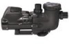
Pumps EcoStar™ SP3400VSP PUMP SERIES REPLACEMENT PARTS Parts for Pump Models: SP3400VSP, SP3400VSPVR 4 5 6 10 11 3 78 9 13 14 12 26 27 15 16 17 23 2 1 19 21 16 18... ea.) Union Gasket Pump Strainer Housing, 2" x 2 1/2" with O-Ring Bracket, Motor Support Riser Base Adapter-Motor Support Motor Assembly Motor Fan Shroud Motor Drive (Includes Digital Control Interface) Motor Drive, SVRS (Includes Digital Control Interface) Motor Drive Display Cover Motor Drive Wiring Cover Digital Control Interface Assembly Wall Mount Kit HAYWARD 28 25 24 Ctn. NOT Pressure Testable) Strainer Cover...
Pumps EcoStar™ SP3400VSP PUMP SERIES REPLACEMENT PARTS Parts for Pump Models: SP3400VSP, SP3400VSPVR 4 5 6 10 11 3 78 9 13 14 12 26 27 15 16 17 23 2 1 19 21 16 18... ea.) Union Gasket Pump Strainer Housing, 2" x 2 1/2" with O-Ring Bracket, Motor Support Riser Base Adapter-Motor Support Motor Assembly Motor Fan Shroud Motor Drive (Includes Digital Control Interface) Motor Drive, SVRS (Includes Digital Control Interface) Motor Drive Display Cover Motor Drive Wiring Cover Digital Control Interface Assembly Wall Mount Kit HAYWARD 28 25 24 Ctn. NOT Pressure Testable) Strainer Cover...


