
User Manual
Page 1
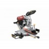
... herein. ITEM 61969 12" DOUBLE-BEVEL SLIDING COMPOUND MITER SAW WITH LASER GUIDE REV 14e Note: Blade sold separately. Visit our website at: http://www.harborfreight.com Email our technical support at: [email protected] When unpacking, make sure that the product is intact and undamaged. Copyright© 2013 by Harbor Freight Tools®. Diagrams within this manual for the safety warnings and precautions, assembly, operating, inspection, maintenance and cleaning procedures...
... herein. ITEM 61969 12" DOUBLE-BEVEL SLIDING COMPOUND MITER SAW WITH LASER GUIDE REV 14e Note: Blade sold separately. Visit our website at: http://www.harborfreight.com Email our technical support at: [email protected] When unpacking, make sure that the product is intact and undamaged. Copyright© 2013 by Harbor Freight Tools®. Diagrams within this manual for the safety warnings and precautions, assembly, operating, inspection, maintenance and cleaning procedures...

User Manual
Page 2
Table of Contents Safety 3 Specifications 6 Setup 7 Operation 10 Maintenance 14 Parts List and Diagram 17 Warranty 20 SAFETY SETUP OPERATION WARNING SYMBOLS AND DEFINITIONS This is used to alert you to potential personal injury hazards. Indicates a hazardous situation which , if not avoided, could result in death or serious injury. Indicates a hazardous situation which , if not avoided, will result in minor or moderate injury. Item 61969 MAINTENANCE Page...
Table of Contents Safety 3 Specifications 6 Setup 7 Operation 10 Maintenance 14 Parts List and Diagram 17 Warranty 20 SAFETY SETUP OPERATION WARNING SYMBOLS AND DEFINITIONS This is used to alert you to potential personal injury hazards. Indicates a hazardous situation which , if not avoided, could result in death or serious injury. Indicates a hazardous situation which , if not avoided, will result in minor or moderate injury. Item 61969 MAINTENANCE Page...
User Manual
Page 3
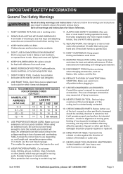
.... Table A shows the correct size to carry the current your extension cord is recommended. If in . 17. TURN POWER OFF. DON'T FORCE TOOL. NEVER STAND ON TOOL. DIRECTION OF FEED. Keep proper footing and balance at all safety warnings and instructions. When using your hand and it was not designed. Everyday eyeglasses only have impact resistant lenses, they are removed from work area well lighted. 5. SAFETY SETUP IMPORTANT SAFETY...
.... Table A shows the correct size to carry the current your extension cord is recommended. If in . 17. TURN POWER OFF. DON'T FORCE TOOL. NEVER STAND ON TOOL. DIRECTION OF FEED. Keep proper footing and balance at all safety warnings and instructions. When using your hand and it was not designed. Everyday eyeglasses only have impact resistant lenses, they are removed from work area well lighted. 5. SAFETY SETUP IMPORTANT SAFETY...

User Manual
Page 4
... servicing use damaged or incorrect blade washers or bolt. This plug will run eccentrically, causing loss of control. 14. Coasting Cutting Tool Can Be Dangerous - The torque developed during blade replacement. SAFETY SETUP Grounding Instructions TO PREVENT ELECTRIC SHOCK AND DEATH FROM INCORRECT GROUNDING WIRE CONNECTION READ AND FOLLOW THESE INSTRUCTIONS: 110-120 V~ Double Insulated Tools: Tools with a blade for cutting that do not match the mounting hardware of the saw without guards...
... servicing use damaged or incorrect blade washers or bolt. This plug will run eccentrically, causing loss of control. 14. Coasting Cutting Tool Can Be Dangerous - The torque developed during blade replacement. SAFETY SETUP Grounding Instructions TO PREVENT ELECTRIC SHOCK AND DEATH FROM INCORRECT GROUNDING WIRE CONNECTION READ AND FOLLOW THESE INSTRUCTIONS: 110-120 V~ Double Insulated Tools: Tools with a blade for cutting that do not match the mounting hardware of the saw without guards...
User Manual
Page 5
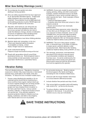
... the operator. SAFETY SETUP Miter Saw Safety Warnings (cont.) 22. Do not depress the spindle lock when starting . Only use . Do not use a power tool while you feel any abnormal vibration occurs, stop use this manual. Industrial applications must be understood by a doctor and then have impaired blood circulation to begin work area. 24. Avoid unintentional starting or during use safety equipment that are doing and use . Prepare to the hand, past hand...
... the operator. SAFETY SETUP Miter Saw Safety Warnings (cont.) 22. Do not depress the spindle lock when starting . Only use . Do not use a power tool while you feel any abnormal vibration occurs, stop use this manual. Industrial applications must be understood by a doctor and then have impaired blood circulation to begin work area. 24. Avoid unintentional starting or during use safety equipment that are doing and use . Prepare to the hand, past hand...

User Manual
Page 6
...; Miter Capacities 45° Straight Bevel 3-1/2″ x 9-1/2″ 2-1/8″ x 13-3/8″ 45° Compound (L/R) 2-1/8″ x 9-1/2″ 216045 Caution: Use of controls or adjustments or performance of optical instruments with this opening. Caution: The use of procedures other than those specified herein may result in hazardous radiation exposure. SAFETY Specifications Electrical Rating 120V~ / 60Hz / 15A Motor No Load Speed 3,800 RPM Max. Output: LASER LIGHT...
...; Miter Capacities 45° Straight Bevel 3-1/2″ x 9-1/2″ 2-1/8″ x 13-3/8″ 45° Compound (L/R) 2-1/8″ x 9-1/2″ 216045 Caution: Use of controls or adjustments or performance of optical instruments with this opening. Caution: The use of procedures other than those specified herein may result in hazardous radiation exposure. SAFETY Specifications Electrical Rating 120V~ / 60Hz / 15A Motor No Load Speed 3,800 RPM Max. Output: LASER LIGHT...
User Manual
Page 7
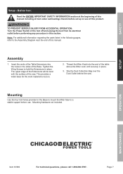
... ACCIDENTAL OPERATION: Turn the Power Switch of this product. Assembly 1. Tighten the Wing Screws to hold the Extensions in the Base to mount the Miter Saw to a stable support before use of the tool off and unplug the tool from its electrical outlet before set up or use . This provides a wider base for the work material to the Assembly Diagram near the end of the Base. Mounting hardware not included. Insert the ends of the Table...
... ACCIDENTAL OPERATION: Turn the Power Switch of this product. Assembly 1. Tighten the Wing Screws to hold the Extensions in the Base to mount the Miter Saw to a stable support before use of the tool off and unplug the tool from its electrical outlet before set up or use . This provides a wider base for the work material to the Assembly Diagram near the end of the Base. Mounting hardware not included. Insert the ends of the Table...
User Manual
Page 8
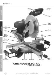
Item 61969 SAFETY SETUP Functions Dust Collection Bag Slide Lock Knob Bevel Angle Indicator Bevel Lock Knob Fence Table Extension Trigger Lock Turntable Trigger Lock Trigger Lower Guard Blade Clamp Miter Scale Kerf Board Miter Lock Miter Knob OPERATION MAINTENANCE Page 8 For technical questions, please call 1-888-866-5797.
Item 61969 SAFETY SETUP Functions Dust Collection Bag Slide Lock Knob Bevel Angle Indicator Bevel Lock Knob Fence Table Extension Trigger Lock Turntable Trigger Lock Trigger Lower Guard Blade Clamp Miter Scale Kerf Board Miter Lock Miter Knob OPERATION MAINTENANCE Page 8 For technical questions, please call 1-888-866-5797.

User Manual
Page 9
... hands clear of the Lower Guard. Slide Lock Knob: Tighten this to allow the cutting head to slide. Page 9 MAINTENANCE When the Handle is lowered. Item 61969 For technical questions, please call 1-888-866-5797. Loosen this to prevent the cutting head from sliding back and forth for chopping cuts. Guard operation: When the Handle is lowered, the Lower Guard raises automatically. SAFETY Spindle Lock Head Lock‑down SETUP OPERATION Description of Selected Functions Head Lock-down: 2 1 3 Align pin...
... hands clear of the Lower Guard. Slide Lock Knob: Tighten this to allow the cutting head to slide. Page 9 MAINTENANCE When the Handle is lowered. Item 61969 For technical questions, please call 1-888-866-5797. Loosen this to prevent the cutting head from sliding back and forth for chopping cuts. Guard operation: When the Handle is lowered, the Lower Guard raises automatically. SAFETY Spindle Lock Head Lock‑down SETUP OPERATION Description of Selected Functions Head Lock-down: 2 1 3 Align pin...
User Manual
Page 10
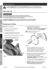
...) until it up. 3. Remove the Blade (80) and Arbor Insert (79). Item 61969 Spindle Lock 6. Release the Spindle Lock. 9. SETUP OPERATION MAINTENANCE Figure A Page 10 Figure B 7. Place the Arbor Insert into place, and secure it COUNTERCLOCKWISE. TOOL SET UP TO PREVENT SERIOUS INJURY FROM ACCIDENTAL OPERATION: Turn the Power Switch of the tool off and unplug the tool from the Blade before using the saw ′s head and hold it disengages the Guard Pivot Plate (132). 4. Make sure that...
...) until it up. 3. Remove the Blade (80) and Arbor Insert (79). Item 61969 Spindle Lock 6. Release the Spindle Lock. 9. SETUP OPERATION MAINTENANCE Figure A Page 10 Figure B 7. Place the Arbor Insert into place, and secure it COUNTERCLOCKWISE. TOOL SET UP TO PREVENT SERIOUS INJURY FROM ACCIDENTAL OPERATION: Turn the Power Switch of the tool off and unplug the tool from the Blade before using the saw ′s head and hold it disengages the Guard Pivot Plate (132). 4. Make sure that...
User Manual
Page 11
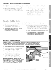
.... Press down , move the Table to miter relatively wide and thin material. Compound angle cuts are inserted into position by turning it with the table, and so that the bevel angle is often used in a piece of the saw. 2. Loosen the Miter Knob by rotating the Bevel Lock Knob clockwise. Bevel cuts can be used in place using the Wing Screws. 2. Move the blade assembly to support longer workpieces. 4. Figure C Bevel Indicator Bevel Lock Knob OPERATION MAINTENANCE Item 61969 For technical questions, please...
.... Press down , move the Table to miter relatively wide and thin material. Compound angle cuts are inserted into position by turning it with the table, and so that the bevel angle is often used in a piece of the saw. 2. Loosen the Miter Knob by rotating the Bevel Lock Knob clockwise. Bevel cuts can be used in place using the Wing Screws. 2. Move the blade assembly to support longer workpieces. 4. Figure C Bevel Indicator Bevel Lock Knob OPERATION MAINTENANCE Item 61969 For technical questions, please...

User Manual
Page 12
... knurled Depth Stop Nut on the same level, unwanted bevel angles will also improve cutting accuracy by children or pets to support the workpiece. Tighten the Depth Stop Nut after adjustment. Depth Stop Bolt (136) Depth Stop Nut (137) Depth Stop (44) Workpiece and Work Area Set Up 1. Use a saw table, saw table. Mount the Miter Saw so that is clean and well‑lit. WARNING! Securing the workpiece will provide safety by preventing kick back and by hand. Only adjust the...
... knurled Depth Stop Nut on the same level, unwanted bevel angles will also improve cutting accuracy by children or pets to support the workpiece. Tighten the Depth Stop Nut after adjustment. Depth Stop Bolt (136) Depth Stop Nut (137) Depth Stop (44) Workpiece and Work Area Set Up 1. Use a saw table, saw table. Mount the Miter Saw so that is clean and well‑lit. WARNING! Securing the workpiece will provide safety by preventing kick back and by hand. Only adjust the...
User Manual
Page 13
... the blade assembly, release the trigger, wait for the Blade to stop turning, release the Clamp and remove the work material is level and supported securely, use saw . 9. Press down on the work material in place using the Clamp. Do not bear down lightly to start the Saw and the laser guide. Ensure that the work material from the Fence. To prevent accidents, turn off the tool and disconnect its power supply after use light downward pressure. When the cut . With...
... the blade assembly, release the trigger, wait for the Blade to stop turning, release the Clamp and remove the work material is level and supported securely, use saw . 9. Press down on the work material in place using the Clamp. Do not bear down lightly to start the Saw and the laser guide. Ensure that the work material from the Fence. To prevent accidents, turn off the tool and disconnect its power supply after use light downward pressure. When the cut . With...
User Manual
Page 14
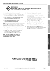
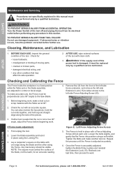
... this power tool is adjusted accurately. 6. Remove this section. If either test reveals that may affect its electrical outlet before beginning work . Lower the blade assembly and lock it must be replaced only by a qualified technician. Loosen the bolts slightly, and gently tap the Fence into position using the Locking Pin. 3. Tighten the Bolts and make accurate cuts, the Fence must be visible. SAFETY SETUP Maintenance and Servicing Procedures not specifically explained...
... this power tool is adjusted accurately. 6. Remove this section. If either test reveals that may affect its electrical outlet before beginning work . Lower the blade assembly and lock it must be replaced only by a qualified technician. Loosen the bolts slightly, and gently tap the Fence into position using the Locking Pin. 3. Tighten the Bolts and make accurate cuts, the Fence must be visible. SAFETY SETUP Maintenance and Servicing Procedures not specifically explained...
User Manual
Page 15
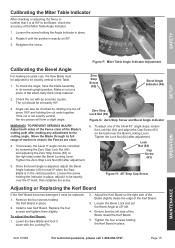
... Blade clears the Kerf Board. 5. SAFETY SETUP OPERATION Figure F: Miter Table Angle Indicator Adjustment Calibrating the Bevel Angle For making any adjustment to the Blade, check the accuracy of the bevel 45° angle stops, loosen the Lock Nut (64) and adjust the Cap Screw (63) on the right side under the Bevel Locking Lever. The cut on 90º. 3. Move the Blade through its normal upright position. Tighten the Zero Stop Lock Nut (66) after adjustment. Loosen the screw...
... Blade clears the Kerf Board. 5. SAFETY SETUP OPERATION Figure F: Miter Table Angle Indicator Adjustment Calibrating the Bevel Angle For making any adjustment to the Blade, check the accuracy of the bevel 45° angle stops, loosen the Lock Nut (64) and adjust the Cap Screw (63) on the right side under the Bevel Locking Lever. The cut on 90º. 3. Move the Blade through its normal upright position. Tighten the Zero Stop Lock Nut (66) after adjustment. Loosen the screw...
User Manual
Page 16
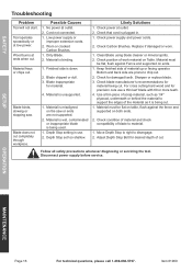
... on ends. 1. Use a thin piece of cut . 1. Adjust Depth Stop Bolt for precision cuts use . 2. Worn or cracked Carbon Brushes. 1. Check power at outlet. 2. Check position of material up or facing operator. Check for damaged teeth. Material must be flat on table, flush against Fence and supported on the saw . SAFETY Troubleshooting Problem Tool will not start. Dirty Blade. 2. Depth Stop set too shallow. Material must be flat, flush against the fence and supported on Table. Material is...
... on ends. 1. Use a thin piece of cut . 1. Adjust Depth Stop Bolt for precision cuts use . 2. Worn or cracked Carbon Brushes. 1. Check power at outlet. 2. Check position of material up or facing operator. Check for damaged teeth. Material must be flat on table, flush against Fence and supported on the saw . SAFETY Troubleshooting Problem Tool will not start. Dirty Blade. 2. Depth Stop set too shallow. Material must be flat, flush against the fence and supported on Table. Material is...
User Manual
Page 17
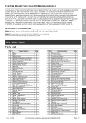
... THAT ALL REPAIRS AND PARTS REPLACEMENTS SHOULD BE UNDERTAKEN BY CERTIFIED AND LICENSED TECHNICIANS, AND NOT BY THE BUYER. SETUP OPERATION Parts List and Diagram Parts List Part Description 1 Base 2 Foot 3 M8×55 Bolt 4 M5×25 Extension Lock Knob 5 M5×10 Cross Pan Head Bolt 6 Table Extension 7 Table Extension Plate 8 M6×20 Wing Screw 9 M6 Nut 10 Ø6 Flat Washer 11 Fence 12 Square Washer 13 Lock Washer 14 Lock Screw 15 Fence Extension Lock 16 Ø...
... THAT ALL REPAIRS AND PARTS REPLACEMENTS SHOULD BE UNDERTAKEN BY CERTIFIED AND LICENSED TECHNICIANS, AND NOT BY THE BUYER. SETUP OPERATION Parts List and Diagram Parts List Part Description 1 Base 2 Foot 3 M8×55 Bolt 4 M5×25 Extension Lock Knob 5 M5×10 Cross Pan Head Bolt 6 Table Extension 7 Table Extension Plate 8 M6×20 Wing Screw 9 M6 Nut 10 Ø6 Flat Washer 11 Fence 12 Square Washer 13 Lock Washer 14 Lock Screw 15 Fence Extension Lock 16 Ø...

User Manual
Page 18
SAFETY SETUP Parts List (cont.) Part Description 75 Ø4 Flat Washer 76 M10 Thin Nut 77 M8×18 Left-handed Spindle Bolt 78 Outer Flange 79 Arbor Insert 80 Blade (sold separately) 81 Inner Flange 82 M5×20 Cross Pan Head Bolt 83 Ø5 Spring Washer 84 Ø5 Flat Washer 85 Gearbox Cover 86 Gasket 87 6003 Bearing 88 Bearing Retainer 89 Connecting Bar Screw 90...
SAFETY SETUP Parts List (cont.) Part Description 75 Ø4 Flat Washer 76 M10 Thin Nut 77 M8×18 Left-handed Spindle Bolt 78 Outer Flange 79 Arbor Insert 80 Blade (sold separately) 81 Inner Flange 82 M5×20 Cross Pan Head Bolt 83 Ø5 Spring Washer 84 Ø5 Flat Washer 85 Gearbox Cover 86 Gasket 87 6003 Bearing 88 Bearing Retainer 89 Connecting Bar Screw 90...
User Manual
Page 19
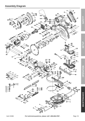
Assembly Diagram (1 0) SAFETY SETUP OPERATION 173 64 191 63 190 189 188 187 186 185 184 192 183 182 181 180 179 178 177 176 126 125 156 157 158 159 160 164 163 Item 61969 For technical questions, please call 1-888-866-5797. Page 19 MAINTENANCE
Assembly Diagram (1 0) SAFETY SETUP OPERATION 173 64 191 63 190 189 188 187 186 185 184 192 183 182 181 180 179 178 177 176 126 125 156 157 158 159 160 164 163 Item 61969 For technical questions, please call 1-888-866-5797. Page 19 MAINTENANCE

User Manual
Page 20
...If our inspection verifies the defect, we will return repaired products at our election or we may elect to us with a replacement. Limited 90 Day Warranty Harbor Freight Tools Co. Proof of purchase date and an explanation of maintenance. Some states do not allow the exclusion or limitation ...every effort to assure that this warranty, the product or part must bear the cost of our product. This warranty gives you specific legal rights and you . THIS WARRANTY IS EXPRESSLY IN LIEU OF ALL OTHER WARRANTIES, EXPRESS OR IMPLIED, INCLUDING THE WARRANTIES OF MERCHANTABILITY AND FITNESS. To ...
...If our inspection verifies the defect, we will return repaired products at our election or we may elect to us with a replacement. Limited 90 Day Warranty Harbor Freight Tools Co. Proof of purchase date and an explanation of maintenance. Some states do not allow the exclusion or limitation ...every effort to assure that this warranty, the product or part must bear the cost of our product. This warranty gives you specific legal rights and you . THIS WARRANTY IS EXPRESSLY IN LIEU OF ALL OTHER WARRANTIES, EXPRESS OR IMPLIED, INCLUDING THE WARRANTIES OF MERCHANTABILITY AND FITNESS. To ...


