Harbor Freight Tools 34706 - 12'' x 33-3/8'' Wood Lathe Support and Manuals
Get Help and Manuals for this Harbor Freight Tools item
View All Support Options Below
Free Harbor Freight Tools 34706 manuals!
Problems with Harbor Freight Tools 34706?
Ask a Question
Free Harbor Freight Tools 34706 manuals!
Problems with Harbor Freight Tools 34706?
Ask a Question
Most Recent Harbor Freight Tools 34706 Questions

Fuse
Is there an inline fuse on this lathe? My lathe has stopped, and doesn't seem to be getting power..
Is there an inline fuse on this lathe? My lathe has stopped, and doesn't seem to be getting power..
(Posted by bigtex0904 1 year ago)
Popular Harbor Freight Tools 34706 Manual Pages
User Manual - Page 2

... 9 12 13
14
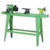
I . Technical data
VARIABLE SPEED WOOD LATHE
MODEL NUMBER
T34706
MOTOR SPEEDS SWITCH DISTANCE BETWEEN CENTERS SWING OVER BED DRIVE ...RIGHT HAND THREAD 3/8" 3/8" 2-1/4" SPUR CENTER - Table of contents
SECTION
I . Electrical information V. Operation IX. Specific safety rules for the wood lathe IV. MORSE #2 TAPER BALL BEARING CENTER - General safety rules III. Assembly ...
User Manual - Page 3
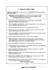
... CONDITIONS. Make sure that are removed from the electrical outlet when making adjustments, changing parts, cleaning or working on floor surfaces that the power switch is accidentally hit. Serious ...it was not designed.
7.
ALWAYS MAKE SURE all tools are slippery with this entire instruction manual. Turn the power switch to a complete stop.
13. DO NOT FORCE THE ...
User Manual - Page 4
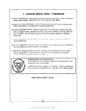
... PROTECTION. ALWAYS wear safety goggles (not glasses).
Follow instructions for alignment of moving parts, binding of moving parts, breakage of parts, improper mounting or any drugs, alcohol or medication that... properly.
19.WARNING: Dust generated from certain materials can be properly repaired or replaced before use.
17. Use dust collection systems whenever possible. Ordinary eyeglasses...
User Manual - Page 5
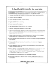
...the turning tools to the wood lathe.
8. For your own safety, read the entire instruction manual before operating.
5. Read the warning label attached to bite into the wood. Always ...thrown out of stock.
12. Specific safety rules for the wood lathe
WARNING: DO NOT OPERATE YOUR WOOD LATHE UNTIL IT IS COMPLETELY
ASSEMBLED AND INSTALLED ACCORDING TO THE INSTRUCTIONS. 1. Do not mount a...
User Manual - Page 6
...is equipped with ALL local codes and ordinances. If it ...installed by a qualified electrician. Always make safety come to select them from the lathe.
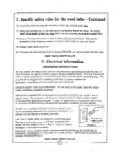
If repair or replacement of the electric cord or plug is necessary, DO NOT connect the equipment grounding conductor to reduce the risk of least resistance for the wood .lathe Continued
16. Electrical information
GROUNDING INSTRUCTIONS...
User Manual - Page 7
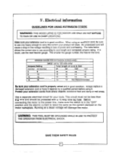
... as the current stamped on the motor nameplate. When using an extension cord, be protected with a 15 Amp time lag fuse. Always replace a damaged extension cord or have it repaired by a qualified person before using 120 volts only)
Ampere Rating
Total length of power and overheating. Use a separate electrical circuit for your...
User Manual - Page 9
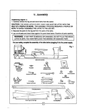
... TO SAFELY ASSEMBLE THE LATHE TO THE LEG SET. 2. VI . Lay out all parts carefully. Examine all parts and check them against the parts listed below.
Fig. 1
ld
LJ\
Lathe bed assembly
(I Extension bed w/hex bolts & washers
4 hex keys 3.4,8,8 mm
o a
Faceplate
.c:0 tri'
Spindle handle w/spring & screw
Instruction manual
Headstock spur center
Push rod
Tailstock cup center...
User Manual - Page 10
... the
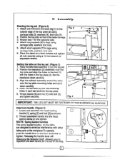
top plate and align the holes in the bed [3]
with other lathe parts or the workpiece.To operate, push the handle lever in each bed and into... washers [4], and nuts [5]. 2. Repeat step 1 for the opposite side. 4. Attach short supports [7] to the
outside edge of the way.
4 0
2 3 1
1
Fig. 4
Set the
headstock down carefully.
3
4. Thread washer [6] and nut [7] onto bolt [5], and ...
User Manual - Page 11

... separate the faceplate from the spindle. 2. Fig. 8
I
3
6 4 Fig. 7
5 4 2 3
WARNING: DO NOT OPERATE YOUR WOOD LATHE UNTIL IT IS COMPLETELY
ASSEMBLED AND ADJUSTED ACCORDING TO THE INSTRUCTIONS.
11
To remove either the headstock spur or the tailstock center, insert the push-out rod [5] into the hole [6] at the opposite end of the...
User Manual - Page 12
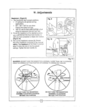
...WARNING: DO NOT TURN THE HEADSTOCK ASSEMBLY MORE THAN 180° CLOCKWISE FROM THE SPINDLE SETTING POSITION OR DAMAGE TO WIRING MAY OCCUR.
0 a
DO NOT TURN THE HEADSTOCK ASSEMBLY ...the lock handle [1]. Pull out the headstock release [2]. The headstock has 5 preset positions.
• 0° setting for all spindle turning applications.
• 60° / 90° / 120° for use when ...
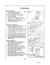
User Manual - Page 13
... the switch
housing.
Opp
L
3 Fig. 15 4 1 2 Store it has
come to the lowest speed setting before operating lathe.
3. Fig. 13 2
Fig. 14
Tailstock (Figure 15)
1. You can extend up to...2. Turn the lever clockwise to increase the speed and counterclockwise to choose lathe speed.
3. To set the speed, pull back on the bed. Lock levers [4] and [2]
before turning the switch...
User Manual - Page 14
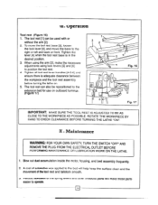
...MAINTENANCE OR LUBRICATION WORK ON THE LATHE.
. Periodic lubrication of the spring levers and other threaded parts will help keep the surface clean and the movement of automotive wax applied to the bed will... make the necessary
adjustments using the arm [21, make these parts easier to the right or left and back or front. VI. Tighten the lever [4] when ...
User Manual - Page 16

...MOTOR ANGULAR SETTING ASSEMBLY
1 MK 1 M65. 1 M66. 3
LOGO LABEL WARNING LABEL SPEED LABLE
M36.
STAND LONG CROSS SUPPORT
1 M54-5. STAND SHORT-CROSS SUPPORT
2
M24....
TOOL REST BODY
1
1 IWO.
PULLEY-SPINDLE (RIGHT)
M13• V-BELT M23
M14. MEDIUM WOODWORKING LATHE PARTS LIST
INDEX NO PARTS DESCRIPTION Q'TY 'INDEX NO PARTS...
User Manual - Page 17
...this warranty , the product or part nos? Proof
of purchase date and an explanation of the complaint must bear the cost of retuning the product.
4
This warranty gives you specific legal rights and you . Pt,...warrants to you may also have other parts and components of our product. If Gilt inspWioa vedites the
defect, we will either repair or replace the product at our expense,but ...
User Manual - Page 18
... AND/OR DISTRIBUTOR EXPRESSLY STATES THAT ALL REPAIRS AND PARTS REPLACEMENTS SHOULD BE
UNDERTAKEN BY CERTIFIED AND LICENSED TECHNICIANS AND NOT BY THE BUYER, THE BUYER ASSUMES ALL RISK AND LIABILITY ARISING OUT OF HIS OR HER REPAIRS TO THE
ORIGINAL PRODUCT OR REPLACEMENT PARTS THER IO, OR
ARISING OW OF HIS OR HER INSTALLATION OF REPLACEMENT PARTS THERETO.
Harbor Freight Tools 34706 Reviews
We have not received any reviews for Harbor Freight Tools yet.