User Manual
Page 1
iCENTRAL MACHINERYC® 12"X36" WOOD LATHE W/REV HEAD SKU I l : T34706 CENTRAL PURCHASING I INC 3491 MISSION OAKS BOULEVARD CAMARILLO ,CALIFORNIA. 93011 1 800 444 3353
iCENTRAL MACHINERYC® 12"X36" WOOD LATHE W/REV HEAD SKU I l : T34706 CENTRAL PURCHASING I INC 3491 MISSION OAKS BOULEVARD CAMARILLO ,CALIFORNIA. 93011 1 800 444 3353

User Manual
Page 2
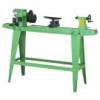
Adjustments VIII. Electrical information V. Technical data VARIABLE SPEED WOOD LATHE MODEL NUMBER T34706 MOTOR SPEEDS SWITCH DISTANCE BETWEEN CENTERS SWING OVER BED DRIVE SPINDLE DRIVE SPINDLE THROUGH HOLE TAILSTOCK SPINDLE THROUGH HOLE TAILSTOCK SPINDLE TRAVEL HEADSTOCK SPUR TAILSTOCK CENTER OVERALL SIZE WEIGHT 120 V,60Hz,1700 RPM (no load) 600 - 2400 RPM REMOVABLE KEY TYPE 33-1/2" 12" 1" DIAMETER, 8 RIGHT HAND THREAD 3/8" 3/8" 2-1/4" SPUR CENTER - MORSE #2 TAPER 60 x 15 x 45-1/2" 177 LBS. Operation IX. Table of contents SECTION I . Technical data...
Adjustments VIII. Electrical information V. Technical data VARIABLE SPEED WOOD LATHE MODEL NUMBER T34706 MOTOR SPEEDS SWITCH DISTANCE BETWEEN CENTERS SWING OVER BED DRIVE SPINDLE DRIVE SPINDLE THROUGH HOLE TAILSTOCK SPINDLE THROUGH HOLE TAILSTOCK SPINDLE TRAVEL HEADSTOCK SPUR TAILSTOCK CENTER OVERALL SIZE WEIGHT 120 V,60Hz,1700 RPM (no load) 600 - 2400 RPM REMOVABLE KEY TYPE 33-1/2" 12" 1" DIAMETER, 8 RIGHT HAND THREAD 3/8" 3/8" 2-1/4" SPUR CENTER - MORSE #2 TAPER 60 x 15 x 45-1/2" 177 LBS. Operation IX. Table of contents SECTION I . Technical data...

User Manual
Page 3
..." position before turning it on tool. 10. DO NOT FORCE THE TOOL to do a job for which it has come to a complete stop. 13. AVOID ACCIDENTAL START-UPS. REMOVE ADJUSTING TOOLS. DO NOT store anything above or near the tool. 6. Keep work on floor surfaces that the power switch is operating. DRESS FOR SAFETY. ALWAYS keep your wood lathe works. ALWAYS remove the power cord plug from the wood lathe before plugging...
..." position before turning it on tool. 10. DO NOT FORCE THE TOOL to do a job for which it has come to a complete stop. 13. AVOID ACCIDENTAL START-UPS. REMOVE ADJUSTING TOOLS. DO NOT store anything above or near the tool. 6. Keep work on floor surfaces that the power switch is operating. DRESS FOR SAFETY. ALWAYS keep your wood lathe works. ALWAYS remove the power cord plug from the wood lathe before plugging...
User Manual
Page 4
...'T OVERREACH. Follow instructions for proper dust removal. A wood lathe can be properly repaired or replaced before use. 17. they ARE NOT safety goggles. times. Keep proper footing and balance at al! CHECK DAMAGED PARTS. SAVE THESE SAFETY RULES 4 Check for alignment of moving parts, binding of moving parts, breakage of parts, improper mounting or any drugs, alcohol or medication that may affect the tool's operation. Use dust collection systems...
...'T OVERREACH. Follow instructions for proper dust removal. A wood lathe can be properly repaired or replaced before use. 17. they ARE NOT safety goggles. times. Keep proper footing and balance at al! CHECK DAMAGED PARTS. SAVE THESE SAFETY RULES 4 Check for alignment of moving parts, binding of moving parts, breakage of parts, improper mounting or any drugs, alcohol or medication that may affect the tool's operation. Use dust collection systems...

User Manual
Page 5
... wood. . Specific safety rules for the wood lathe WARNING: DO NOT OPERATE YOUR WOOD LATHE UNTIL IT IS COMPLETELY ASSEMBLED AND INSTALLED ACCORDING TO THE INSTRUCTIONS. 1. Do not allow the turning tools to the faceplate. Remove all locks before mounting it vibrates, there is being thrown from the lathe. 11. For your own safety, read the entire instruction manual before turning on the faceplate. Use the lowest speed when starting a new workpiece. 7. If the lathe...
... wood. . Specific safety rules for the wood lathe WARNING: DO NOT OPERATE YOUR WOOD LATHE UNTIL IT IS COMPLETELY ASSEMBLED AND INSTALLED ACCORDING TO THE INSTRUCTIONS. 1. Do not allow the turning tools to the faceplate. Remove all locks before mounting it vibrates, there is being thrown from the lathe. 11. For your own safety, read the entire instruction manual before turning on the faceplate. Use the lowest speed when starting a new workpiece. 7. If the lathe...
User Manual
Page 6
... the grounding instructions, or if you remove them . 18. SAVE THESE SAFETY RULES N . The plug MUST be plugged into a matching outlet that has an equipment grounding conductor and a grounding plug. CHECK with ALL local codes and ordinances. Complete the hand-sanding of the cutting tool at all workpieces BEFORE you are found. 19. A. Repair or replace damaged or worn cord immediately...
... the grounding instructions, or if you remove them . 18. SAVE THESE SAFETY RULES N . The plug MUST be plugged into a matching outlet that has an equipment grounding conductor and a grounding plug. CHECK with ALL local codes and ordinances. Complete the hand-sanding of the cutting tool at all workpieces BEFORE you are found. 19. A. Repair or replace damaged or worn cord immediately...

User Manual
Page 7
... motor to carry the current your extension cord is in good condition. Use a separate electrical circuit for your extension cords from sharp objects, excessive heat and damp or wet areas. Protect your tools. Running at a lower voltage will draw. The table below shows the correct size to use one heavy enough to the power line, make sure the switch is properly wired...
... motor to carry the current your extension cord is in good condition. Use a separate electrical circuit for your extension cords from sharp objects, excessive heat and damp or wet areas. Protect your tools. Running at a lower voltage will draw. The table below shows the correct size to use one heavy enough to the power line, make sure the switch is properly wired...

User Manual
Page 8
Headstock Speed control ON-OFF switch w/key Headstock release 3 eadstock spindle Spur center Tool rest arm Motor Extension bed Head lock Tool rest base Bed Base lock lever Spindle lock Tailstock lock Tool rest Tailstock spindle Cup center 1 L11 Tool rest lock lever Arm lock lever ©© 'ad Faceplate Hand wheel Tailstock Legs © ti o O ro. cV Wrenches Push out rod
Headstock Speed control ON-OFF switch w/key Headstock release 3 eadstock spindle Spur center Tool rest arm Motor Extension bed Head lock Tool rest base Bed Base lock lever Spindle lock Tailstock lock Tool rest Tailstock spindle Cup center 1 L11 Tool rest lock lever Arm lock lever ©© 'ad Faceplate Hand wheel Tailstock Legs © ti o O ro. cV Wrenches Push out rod
User Manual
Page 9
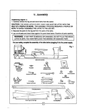
.... 1 ld LJ\ Lathe bed assembly (I Extension bed w/hex bolts & washers 4 hex keys 3.4,8,8 mm o a Faceplate .c:0 tri' Spindle handle w/spring & screw Instruction manual Headstock spur center Push rod Tailstock cup center 2 - 32mm flat wrenches 32 nuts 24 flat washers 8 lock washers 11///1 24 carriage bolts itilMINNUN 8 hex bolts 2 long leg supports a 2 front legs & 2 rear legs 9 o o a a a a a 2 short leg supports 2 top leg plates Lay out all parts carefully. Carefully remove the leg set from the...
.... 1 ld LJ\ Lathe bed assembly (I Extension bed w/hex bolts & washers 4 hex keys 3.4,8,8 mm o a Faceplate .c:0 tri' Spindle handle w/spring & screw Instruction manual Headstock spur center Push rod Tailstock cup center 2 - 32mm flat wrenches 32 nuts 24 flat washers 8 lock washers 11///1 24 carriage bolts itilMINNUN 8 hex bolts 2 long leg supports a 2 front legs & 2 rear legs 9 o o a a a a a 2 short leg supports 2 top leg plates Lay out all parts carefully. Carefully remove the leg set from the...
User Manual
Page 10
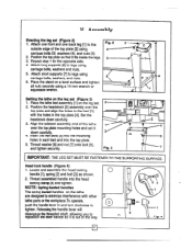
... THE SUPPORTING SURFACE. NOTE: Spring loaded handles The spring loaded handles on the leg 'set (Figure 3) 1. Place the lathe bed assembly [1] on the lathe are designed to legs using carriage bolts, washers, and nuts. 6. Repeat step 1 for the opposite side. 4. Insert the hex bolts [5] into the head locking clamp [4] and tighten. Locate and assemble the head locking handle [1], spring [2] and bolt [3] as shown. 2. Set the headstock down carefully. 3 4. Thread assembled handle into the mounting / 47 0 holes in and turn...
... THE SUPPORTING SURFACE. NOTE: Spring loaded handles The spring loaded handles on the leg 'set (Figure 3) 1. Place the lathe bed assembly [1] on the lathe are designed to legs using carriage bolts, washers, and nuts. 6. Repeat step 1 for the opposite side. 4. Insert the hex bolts [5] into the head locking clamp [4] and tighten. Locate and assemble the head locking handle [1], spring [2] and bolt [3] as shown. 2. Set the headstock down carefully. 3 4. Thread assembled handle into the mounting / 47 0 holes in and turn...

User Manual
Page 11
... with the flat head brass wood screws. Remove the headstock spur from the headstock spindle using the two wrenches provided [2] to the spindle. 3. The extension bed is attached to the bed, align the bolt holes [2] with the hex key provided. Fig. 8 I 3 6 4 Fig. 7 5 4 2 3 WARNING: DO NOT OPERATE YOUR WOOD LATHE UNTIL IT IS COMPLETELY ASSEMBLED AND ADJUSTED ACCORDING TO THE INSTRUCTIONS. 11 To remove either the headstock...
... with the flat head brass wood screws. Remove the headstock spur from the headstock spindle using the two wrenches provided [2] to the spindle. 3. The extension bed is attached to the bed, align the bolt holes [2] with the hex key provided. Fig. 8 I 3 6 4 Fig. 7 5 4 2 3 WARNING: DO NOT OPERATE YOUR WOOD LATHE UNTIL IT IS COMPLETELY ASSEMBLED AND ADJUSTED ACCORDING TO THE INSTRUCTIONS. 11 To remove either the headstock...
User Manual
Page 12
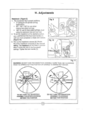
... use for face plate turnings when using the extension bed and tool rest. 2. Tighten the lock handle [1]. Fig. 9 2 Fig. 10 2 oi Fig. 11 WARNING: DO NOT TURN THE HEADSTOCK ASSEMBLY MORE THAN 180° CLOCKWISE FROM THE SPINDLE SETTING POSITION OR DAMAGE TO WIRING MAY OCCUR. 0 a DO NOT TURN THE HEADSTOCK ASSEMBLY COUNTERCLOCKWISE BEYOND THIS POSITION DO NOT TURN THE HEADSTOCK ASSEMBLY CLOCKWISE BEYOND THIS POSITION 12 Adjustments Headstock...
... use for face plate turnings when using the extension bed and tool rest. 2. Tighten the lock handle [1]. Fig. 9 2 Fig. 10 2 oi Fig. 11 WARNING: DO NOT TURN THE HEADSTOCK ASSEMBLY MORE THAN 180° CLOCKWISE FROM THE SPINDLE SETTING POSITION OR DAMAGE TO WIRING MAY OCCUR. 0 a DO NOT TURN THE HEADSTOCK ASSEMBLY COUNTERCLOCKWISE BEYOND THIS POSITION DO NOT TURN THE HEADSTOCK ASSEMBLY CLOCKWISE BEYOND THIS POSITION 12 Adjustments Headstock...
User Manual
Page 13
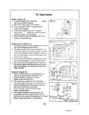
... the spindle lock lever [4] and then turning the 5 hand wheel [5]. Lock levers [4] and [2] before turning the switch off (Figure 14), otherwise the motor may not start. Never leave the lathe unattended until it in the "OFF" position, remove the switch key from the switch housing. You must be accessed from the tailstock housing. Operation Switch (Figure 12) 1. Turn the lever clockwise to increase the speed and counterclockwise to choose lathe speed. 3. You can use the speed control lever...
... the spindle lock lever [4] and then turning the 5 hand wheel [5]. Lock levers [4] and [2] before turning the switch off (Figure 14), otherwise the motor may not start. Never leave the lathe unattended until it in the "OFF" position, remove the switch key from the switch housing. You must be accessed from the tailstock housing. Operation Switch (Figure 12) 1. Turn the lever clockwise to increase the speed and counterclockwise to choose lathe speed. 3. You can use the speed control lever...
User Manual
Page 14
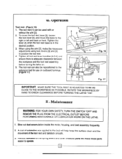
... OWN SAFETY, TURN THE SWITCH "OFF" AND REMOVE THE PLUG FROM THE ELECTRICAL OUTLET BEFORE PERFORMING MAINTENANCE OR LUBRICATION WORK ON THE LATHE. . A coat of the tool rest and tailstock smooth. 3. The tool rest [1] can also be used with or without the arm [2]. 2. Tighten the lever [4] when the tool rest base is adequate clearance between the workpiece and the tool rest assembly before turning the lathe on outboard turnings. (Figure...
... OWN SAFETY, TURN THE SWITCH "OFF" AND REMOVE THE PLUG FROM THE ELECTRICAL OUTLET BEFORE PERFORMING MAINTENANCE OR LUBRICATION WORK ON THE LATHE. . A coat of the tool rest and tailstock smooth. 3. The tool rest [1] can also be used with or without the arm [2]. 2. Tighten the lever [4] when the tool rest base is adequate clearance between the workpiece and the tool rest assembly before turning the lathe on outboard turnings. (Figure...

User Manual
Page 16
.... MOTOR NNE PLATE FOR MOTOR COVER-MOTOR ANGULAR SETTING ASSEMBLY 1 MK 1 M65. 1 M66. 3 LOGO LABEL WARNING LABEL SPEED LABLE M36. STAND SWITCH LEG 1 M21-1. SCREW I . HEX KIT M18 2 M8. RACK 1 M54-I M54 4. WRENCH M26. WASHER 24 M31. POWER CORD 1 M33. SCREW M1OX 25 2 M18. PULLEY-SPINDLE(LEFT) M15. 5-24 1 M48-I M55. EXTENSION BED 1 M17. SLEEVE I . TOOL REST BODY 1 1 IWO. MEDIUM WOODWORKING LATHE PARTS LIST INDEX NO PARTS DESCRIPTION Q'TY 'INDEX NO PARTS...
.... MOTOR NNE PLATE FOR MOTOR COVER-MOTOR ANGULAR SETTING ASSEMBLY 1 MK 1 M65. 1 M66. 3 LOGO LABEL WARNING LABEL SPEED LABLE M36. STAND SWITCH LEG 1 M21-1. SCREW I . HEX KIT M18 2 M8. RACK 1 M54-I M54 4. WRENCH M26. WASHER 24 M31. POWER CORD 1 M33. SCREW M1OX 25 2 M18. PULLEY-SPINDLE(LEFT) M15. 5-24 1 M48-I M55. EXTENSION BED 1 M17. SLEEVE I . TOOL REST BODY 1 1 IWO. MEDIUM WOODWORKING LATHE PARTS LIST INDEX NO PARTS DESCRIPTION Q'TY 'INDEX NO PARTS...

User Manual
Page 17
... inspWioa vedites the defect, we will either repair or replace the product at our expense,but if we...parts and components of retuning the product. 4 This warranty gives you specific legal rights and you with transpot laden otiarges prepaid. Pt, •;PA t . ' :113. • .1 -7,- - This warranty...replac-ernent. Box 6009 • Camarilla,CA93011 • (800)444-3353 • fi• te'44 1 41;-,7\ 2rD ,. •$ • 41 F Harbor Freight Tool company also warrants to refund the purchase price it we is determine there is free from the use of our warranty...
... inspWioa vedites the defect, we will either repair or replace the product at our expense,but if we...parts and components of retuning the product. 4 This warranty gives you specific legal rights and you with transpot laden otiarges prepaid. Pt, •;PA t . ' :113. • .1 -7,- - This warranty...replac-ernent. Box 6009 • Camarilla,CA93011 • (800)444-3353 • fi• te'44 1 41;-,7\ 2rD ,. •$ • 41 F Harbor Freight Tool company also warrants to refund the purchase price it we is determine there is free from the use of our warranty...
User Manual
Page 18
... THE FOLLOWING CAREFULLY THE MANUFACTURE AND/OR DISTRIBUTOR HAS PROVIDED THE FARTS DIAGRAM IN THIS MANUAL AS A RE;ERENCE TOOL ON;_Y. IN FACT, THE MANUFACTURER AND/OR DISTRIBUTOR EXPRESSLY STATES THAT ALL REPAIRS AND PARTS REPLACEMENTS SHOULD BE UNDERTAKEN BY CERTIFIED AND LICENSED TECHNICIANS AND NOT BY THE... AND LIABILITY ARISING OUT OF HIS OR HER REPAIRS TO THE ORIGINAL PRODUCT OR REPLACEMENT PARTS THER IO, OR ARISING OW OF HIS OR HER INSTALLATION OF REPLACEMENT PARTS THERETO. NEITHER THE MANUFACTURER NOR DISTRIBUTOR MAKES ANY REPRESENTATION OR WARRANTY OF ANY KIND TO THE BUYER THAT HE ...
... THE FOLLOWING CAREFULLY THE MANUFACTURE AND/OR DISTRIBUTOR HAS PROVIDED THE FARTS DIAGRAM IN THIS MANUAL AS A RE;ERENCE TOOL ON;_Y. IN FACT, THE MANUFACTURER AND/OR DISTRIBUTOR EXPRESSLY STATES THAT ALL REPAIRS AND PARTS REPLACEMENTS SHOULD BE UNDERTAKEN BY CERTIFIED AND LICENSED TECHNICIANS AND NOT BY THE... AND LIABILITY ARISING OUT OF HIS OR HER REPAIRS TO THE ORIGINAL PRODUCT OR REPLACEMENT PARTS THER IO, OR ARISING OW OF HIS OR HER INSTALLATION OF REPLACEMENT PARTS THERETO. NEITHER THE MANUFACTURER NOR DISTRIBUTOR MAKES ANY REPRESENTATION OR WARRANTY OF ANY KIND TO THE BUYER THAT HE ...


