
User Manual
Page 2
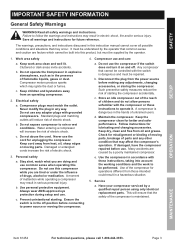
Item 61454 Indicates a hazardous situation which, if not avoided, will result in minor or moderate injury. Indicates a hazardous situation which , if not avoided... a hazardous situation which , if not avoided, could result in death or serious injury. SETUP OPERATION MAINTENANCE Page 2 For technical questions, please call 1-800-444-3353. SAFETY Table of Contents Safety 2 Setup 6 Specifications 6 Operation 11 Maintenance 14 Parts List and Diagram 18 Warranty 20 WARNING SYMBOLS AND DEFINITIONS This is used to alert you to potential personal injury hazards. It is the...
Item 61454 Indicates a hazardous situation which, if not avoided, will result in minor or moderate injury. Indicates a hazardous situation which , if not avoided... a hazardous situation which , if not avoided, could result in death or serious injury. SETUP OPERATION MAINTENANCE Page 2 For technical questions, please call 1-800-444-3353. SAFETY Table of Contents Safety 2 Setup 6 Specifications 6 Operation 11 Maintenance 14 Parts List and Diagram 18 Warranty 20 WARNING SYMBOLS AND DEFINITIONS This is used to alert you to potential personal injury hazards. It is the...
User Manual
Page 3
... from the power source before use the compressor if the switch does not turn it . c. Store an idle compressor out of the reach of inattention while operating a compressor may affect the compressor's operation. Maintain the compressor. Keep the compressor clean for lubricating and changing accessories. Follow instructions for better and safer performance. Check for operations different from oil and grease. e. Service a. This will reduce risk of electric shock. 3. Page...
... from the power source before use the compressor if the switch does not turn it . c. Store an idle compressor out of the reach of inattention while operating a compressor may affect the compressor's operation. Maintain the compressor. Keep the compressor clean for lubricating and changing accessories. Follow instructions for better and safer performance. Check for operations different from oil and grease. e. Service a. This will reduce risk of electric shock. 3. Page...

User Manual
Page 4
... not cover compressor during operation. If you choose to persons. 14. b. Maintain labels and nameplates on level surface. If unreadable or missing, contact Harbor Freight Tools for a minimum working . 6. Check oil level daily and fill to supply breathing air. 5. OPERATION MAINTENANCE Page 4 For technical questions, please call 1-800-444-3353. Item 61454 do not adjust regulator higher than marked maximum pressure of power and...
... not cover compressor during operation. If you choose to persons. 14. b. Maintain labels and nameplates on level surface. If unreadable or missing, contact Harbor Freight Tools for a minimum working . 6. Check oil level daily and fill to supply breathing air. 5. OPERATION MAINTENANCE Page 4 For technical questions, please call 1-800-444-3353. Item 61454 do not adjust regulator higher than marked maximum pressure of power and...
User Manual
Page 5
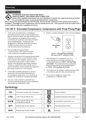
... Item 61454 For technical questions, please call 1-800-444-3353. Do not modify the power cord plug provided with Three Prong Plugs 1. if it repaired by a qualified electrician. 3. Check with all local codes and ordinances. 2. Use only 3-wire extension cords that have the proper outlet installed by a service facility before use the compressor if the power cord or plug is properly grounded. 5. Page 5 MAINTENANCE Never remove...
... Item 61454 For technical questions, please call 1-800-444-3353. Do not modify the power cord plug provided with Three Prong Plugs 1. if it repaired by a qualified electrician. 3. Check with all local codes and ordinances. 2. Use only 3-wire extension cords that have the proper outlet installed by a service facility before use the compressor if the power cord or plug is properly grounded. 5. Page 5 MAINTENANCE Never remove...

User Manual
Page 6
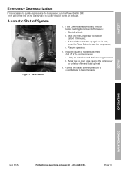
...) - SAFETY SETUP Specifications Electrical Rating Air Outlet Size Air Pressure Shut-off Restart Air Tank Capacity Air Flow Capacity Oil Capacity Oil Type Sound Level 120V~ / 60Hz / 14A (Dedicated circuit recommended) 1/4″ -18 NPT 125 PSI 95 PSI 21 Gallons 4.7 CFM @ 90 PSI 5.8 CFM @ 40 PSI 5.6 oz. for putting into use of this product. Note: For additional information regarding the parts listed in -line shutoff valve, air hose and tool Pressure Switch (54) OFF ON/OFF Pressure Power Regulator Lever (74) Safety Valve...
...) - SAFETY SETUP Specifications Electrical Rating Air Outlet Size Air Pressure Shut-off Restart Air Tank Capacity Air Flow Capacity Oil Capacity Oil Type Sound Level 120V~ / 60Hz / 14A (Dedicated circuit recommended) 1/4″ -18 NPT 125 PSI 95 PSI 21 Gallons 4.7 CFM @ 90 PSI 5.8 CFM @ 40 PSI 5.6 oz. for putting into use of this product. Note: For additional information regarding the parts listed in -line shutoff valve, air hose and tool Pressure Switch (54) OFF ON/OFF Pressure Power Regulator Lever (74) Safety Valve...
User Manual
Page 7
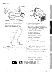
.... f. SAFETY SETUP Assembly Tank (70) Cylinder Head (7) Nut (24) Hex Nut (65) Foot Pad (67) Figure C Wheel (63) Washer (68) Sleeve (64a) Screw (69) Washer (64b) Bolt (64) 1. Attach the Wheels (63) to the bottom of the Cylinder Head (7). 4. Attach the Foot Pads (67) to the Tank (70), using the Screws (69) and Washers (68). Turn the Power Switch ON. Let the unit run for needed accessories. Turn the Power Switch OFF. Unplug the Power Cord and remove...
.... f. SAFETY SETUP Assembly Tank (70) Cylinder Head (7) Nut (24) Hex Nut (65) Foot Pad (67) Figure C Wheel (63) Washer (68) Sleeve (64a) Screw (69) Washer (64b) Bolt (64) 1. Attach the Wheels (63) to the bottom of the Cylinder Head (7). 4. Attach the Foot Pads (67) to the Tank (70), using the Screws (69) and Washers (68). Turn the Power Switch ON. Let the unit run for needed accessories. Turn the Power Switch OFF. Unplug the Power Cord and remove...
User Manual
Page 8
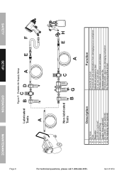
SAFETY SETUP OPERATION MAINTENANCE Page 8 Figure F: Portable Air Supply Setup Lubricated Tools BC D A E F A For technical questions, please call 1-800-444-3353. Non-lubricated Tools C EH BG A Description A Air Hose B Filter C Regulator D Lubricator (optional) E Coupler and Plug F Leader Hose (optional) G Air Cleaner / Dryer (optional) H Air Adjusting Valve (optional) Function Connects air to tool Prevents dirt and condensation from damaging tool or workpiece Adjusts air pressure to tool For air tool lubrication Provides quick connection and release Increases coupler...
SAFETY SETUP OPERATION MAINTENANCE Page 8 Figure F: Portable Air Supply Setup Lubricated Tools BC D A E F A For technical questions, please call 1-800-444-3353. Non-lubricated Tools C EH BG A Description A Air Hose B Filter C Regulator D Lubricator (optional) E Coupler and Plug F Leader Hose (optional) G Air Cleaner / Dryer (optional) H Air Adjusting Valve (optional) Function Connects air to tool Prevents dirt and condensation from damaging tool or workpiece Adjusts air pressure to tool For air tool lubrication Provides quick connection and release Increases coupler...
User Manual
Page 9
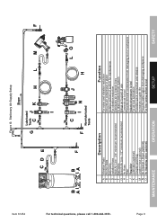
... Pads B Anchor Bolts C Ball Valve D Isolation Hose E Main Air Line - 3/4″ minimum recommended F Ball Valve G Branch Air Line -1/2″ minimum recommended H Air Hose I For technical questions, please call 1-800-444-3353. Item 61454 Figure G: Stationary Air Supply Setup Slope Lubricated G Tools C J K H L M F CD E I Filter J Regulator K Lubricator (optional) L Coupler and Plug M Leader Hose (optional) N Air Cleaner / Dryer (optional) O Air Adjusting Valve (optional) MAINTENANCE OPERATION Function For noise and vibration reduction Secures air compressor...
... Pads B Anchor Bolts C Ball Valve D Isolation Hose E Main Air Line - 3/4″ minimum recommended F Ball Valve G Branch Air Line -1/2″ minimum recommended H Air Hose I For technical questions, please call 1-800-444-3353. Item 61454 Figure G: Stationary Air Supply Setup Slope Lubricated G Tools C J K H L M F CD E I Filter J Regulator K Lubricator (optional) L Coupler and Plug M Leader Hose (optional) N Air Cleaner / Dryer (optional) O Air Adjusting Valve (optional) MAINTENANCE OPERATION Function For noise and vibration reduction Secures air compressor...
User Manual
Page 10
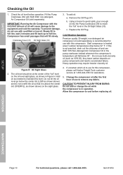
... damage to the equipment and void the warranty. Allow the compressor to accelerated failure. SAFETY Checking the Oil 1. IMPORTANT: Running the Air Compressor with this compressor. Crankcase Cover (31) Oil Sight Glass (33) OIL LEVEL OVERFILL FULL LOW Tank (70) Figure H: Oil Sight Glass 2. Start compressor in Figure H. SETUP OPERATION MAINTENANCE Page 10 For technical questions, please call Harbor Freight Tools customer service at the center of the "full...
... damage to the equipment and void the warranty. Allow the compressor to accelerated failure. SAFETY Checking the Oil 1. IMPORTANT: Running the Air Compressor with this compressor. Crankcase Cover (31) Oil Sight Glass (33) OIL LEVEL OVERFILL FULL LOW Tank (70) Figure H: Oil Sight Glass 2. Start compressor in Figure H. SETUP OPERATION MAINTENANCE Page 10 For technical questions, please call Harbor Freight Tools customer service at the center of the "full...
User Manual
Page 11
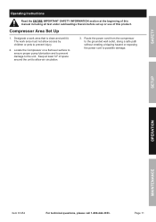
SAFETY Operating Instructions Read the ENTIRE IMPORTANT SAFETY INFORMATION section at least 12″ of this manual including all text under subheadings therein before set up or use of space around the unit to allow access by children or pets to prevent injury. 2. Compressor Area Set Up 1. Keep at the beginning of this product. Page 11 SETUP OPERATION MAINTENANCE Item 61454 For technical questions...
SAFETY Operating Instructions Read the ENTIRE IMPORTANT SAFETY INFORMATION section at least 12″ of this manual including all text under subheadings therein before set up or use of space around the unit to allow access by children or pets to prevent injury. 2. Compressor Area Set Up 1. Keep at the beginning of this product. Page 11 SETUP OPERATION MAINTENANCE Item 61454 For technical questions...
User Manual
Page 12
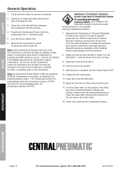
..., turn off automatically when the air pressure reaches 125 PSI. Unplug the Air Compressor. 13. Bleed air from the tool then disconnect the tool. 15. Do not remove the Drain Valve. 16. SAFETY General Operation 1. Any change to the automatic pressure levels may cause excess pressure to decrease pressure. Note: As long as needed. 11. WARNING! Open the in -line Shutoff Valve between the compressor and the air hose. 4. Item 61454 Check for air leaks...
..., turn off automatically when the air pressure reaches 125 PSI. Unplug the Air Compressor. 13. Bleed air from the tool then disconnect the tool. 15. Do not remove the Drain Valve. 16. SAFETY General Operation 1. Any change to the automatic pressure levels may cause excess pressure to decrease pressure. Note: As long as needed. 11. WARNING! Open the in -line Shutoff Valve between the compressor and the air hose. 4. Item 61454 Check for air leaks...
User Manual
Page 13
... use to avoid damage to quickly release stored air pressure. d. Resume operation. 2. Correct any issues before reaching its own, press the Reset Button to quickly depressurize the Compressor, turn the Power Switch OFF. Page 13 Wait until the Compressor cools down (about 10 minutes); b. c. Then, pull on the ring on its normal cutoff pressure: a. Using an extension cord that is necessary to start up heat. 3. b. SETUP OPERATION MAINTENANCE Item 61454...
... use to avoid damage to quickly release stored air pressure. d. Resume operation. 2. Correct any issues before reaching its own, press the Reset Button to quickly depressurize the Compressor, turn the Power Switch OFF. Page 13 Wait until the Compressor cools down (about 10 minutes); b. c. Then, pull on the ring on its normal cutoff pressure: a. Using an extension cord that is necessary to start up heat. 3. b. SETUP OPERATION MAINTENANCE Item 61454...
User Manual
Page 14
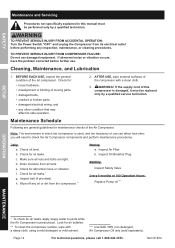
... further use damaged equipment. SAFETY SETUP Maintenance and Servicing Procedures not specifically explained in which the compressor is used, and the frequency of the Air Compressor. Check for abnormal noise or vibration. If the supply cord of moving parts, • damaged belts, • cracked or broken parts, • damaged electrical wiring, and • any oil or dirt from air tank. Item 61454 TO PREVENT SERIOUS INJURY FROM ACCIDENTAL OPERATION: Turn the Power Switch...
... further use damaged equipment. SAFETY SETUP Maintenance and Servicing Procedures not specifically explained in which the compressor is used, and the frequency of the Air Compressor. Check for abnormal noise or vibration. If the supply cord of moving parts, • damaged belts, • cracked or broken parts, • damaged electrical wiring, and • any oil or dirt from air tank. Item 61454 TO PREVENT SERIOUS INJURY FROM ACCIDENTAL OPERATION: Turn the Power Switch...
User Manual
Page 15
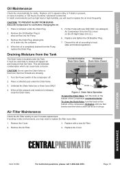
... need to release all the pressure and moisture is located under the Tank. It must be used daily to replace the oil more frequently. SAFETY SETUP Oil Maintenance Check the oil periodically for clarity. Place a container under the Drain Valve. 3. Remove the Oil Breather Plug to the FULL level on the bottom of the compressor off. 2. CAUTION! Replace with new SAE 30W, non-detergent, Air Compressor Oil to allow air...
... need to release all the pressure and moisture is located under the Tank. It must be used daily to replace the oil more frequently. SAFETY SETUP Oil Maintenance Check the oil periodically for clarity. Place a container under the Drain Valve. 3. Remove the Oil Breather Plug to the FULL level on the bottom of the compressor off. 2. CAUTION! Replace with new SAE 30W, non-detergent, Air Compressor Oil to allow air...
User Manual
Page 16
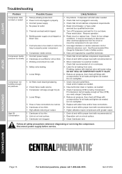
...-3353. Reset circuit or replace fuse. Crankcase oil overfilled or oil too thick. 3. Hose or hose connections too narrow. 6. Check if accessory CFM is in properly. 3. No problem. Check that circuit matches compressor requirements. 4. Check Valve needs service. 3. Item 61454 Drain oil and refill to proper level with a soap solution for air leaks and tighten as needed . 2. SAFETY SETUP Troubleshooting Problem Compressor does not start when needed . Check that recommended oil is met by Compressor. Working environment...
...-3353. Reset circuit or replace fuse. Crankcase oil overfilled or oil too thick. 3. Hose or hose connections too narrow. 6. Check if accessory CFM is in properly. 3. No problem. Check that circuit matches compressor requirements. 4. Check Valve needs service. 3. Item 61454 Drain oil and refill to proper level with a soap solution for air leaks and tighten as needed . 2. SAFETY SETUP Troubleshooting Problem Compressor does not start when needed . Check that recommended oil is met by Compressor. Working environment...
User Manual
Page 17
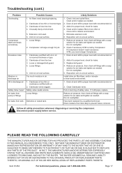
... Compressor. Extension cord used. 6. Reposition unit on a level surface. 1. Unusually dusty environment. 5. Compressor not large enough for leaks. 4. Loose fittings. Check inlet and outlet filters. Reduce air pressure, then check all safety precautions whenever diagnosing or servicing the compressor. Replace belt guard. 4. Drain moisture from tank Possible Causes 1. OPERATION MAINTENANCE PLEASE READ THE FOLLOWING CAREFULLY THE MANUFACTURER AND/OR DISTRIBUTOR HAS PROVIDED THE PARTS LIST AND ASSEMBLY DIAGRAM...
... Compressor. Extension cord used. 6. Reposition unit on a level surface. 1. Unusually dusty environment. 5. Compressor not large enough for leaks. 4. Loose fittings. Check inlet and outlet filters. Reduce air pressure, then check all safety precautions whenever diagnosing or servicing the compressor. Replace belt guard. 4. Drain moisture from tank Possible Causes 1. OPERATION MAINTENANCE PLEASE READ THE FOLLOWING CAREFULLY THE MANUFACTURER AND/OR DISTRIBUTOR HAS PROVIDED THE PARTS LIST AND ASSEMBLY DIAGRAM...
User Manual
Page 18
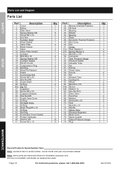
... 1 63 Wheel 2 64 Bolt M12 x 55 1 64a Sleeve 1 64b Washer 12 1 65 Hex Nut M12 1 66 Drain Valve 1 67 Foot Pad 1 68 Washer 1 69 Screw M6 x 25 1 70 Tank 1 71 Bolt M6 x 10 1 72 Handle 1 73 Safety Valve 1 74 Pressure Regulator 1 75 Motor Cord 1 76 Quick Coupler 10 77 Output Pressure Gauge 10 78 Plug Qty 1 1 1 1 1 1 1 1 1 1 4 4 4 1 1 1 1 1 1 1 2 2 1 1 2 2 2 2 2 1 2 2 2 1 4 1 1 1 1 1 1 1 OPERATION MAINTENANCE Record Product's Serial Number Here: Note: If product has no serial number, record...
... 1 63 Wheel 2 64 Bolt M12 x 55 1 64a Sleeve 1 64b Washer 12 1 65 Hex Nut M12 1 66 Drain Valve 1 67 Foot Pad 1 68 Washer 1 69 Screw M6 x 25 1 70 Tank 1 71 Bolt M6 x 10 1 72 Handle 1 73 Safety Valve 1 74 Pressure Regulator 1 75 Motor Cord 1 76 Quick Coupler 10 77 Output Pressure Gauge 10 78 Plug Qty 1 1 1 1 1 1 1 1 1 1 4 4 4 1 1 1 1 1 1 1 2 2 1 1 2 2 2 2 2 1 2 2 2 1 4 1 1 1 1 1 1 1 OPERATION MAINTENANCE Record Product's Serial Number Here: Note: If product has no serial number, record...
User Manual
Page 19
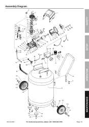
Assembly Diagram SAFETY SETUP OPERATION MAINTENANCE b a a b Item 61454 For technical questions, please call 1-800-444-3353. Page 19
Assembly Diagram SAFETY SETUP OPERATION MAINTENANCE b a a b Item 61454 For technical questions, please call 1-800-444-3353. Page 19
User Manual
Page 20
..., repairs or alterations outside our facilities, criminal activity, improper installation, normal wear and tear, or to us with a replacement. Proof of purchase date and an explanation of the complaint must be liable for incidental, contingent, special or consequential damages arising from causes not within the scope of our warranty, then you . Limited 90 Day Warranty Harbor Freight Tools...
..., repairs or alterations outside our facilities, criminal activity, improper installation, normal wear and tear, or to us with a replacement. Proof of purchase date and an explanation of the complaint must be liable for incidental, contingent, special or consequential damages arising from causes not within the scope of our warranty, then you . Limited 90 Day Warranty Harbor Freight Tools...


