Manual
Page 3
Table of Contents Box Contents...4 MSH61DI Motherboard Layout 5 Chapter 1 Hardware Installation 7 1-1 Installation Precautions 7 1-2 Product Specifications 8 1-3 Installing the CPU and CPU Cooler 10 1-3-1 Installing the CPU...10 1-3-2 Installing the CPU Cooler 12 1-4 Installing the Memory 13 1-4-1 Dual Channel ...1-6 Internal Connectors 17 Chapter 2 BIOS Setup 27 2-1 The Main Menu 29 2-2 Advanced Menu 31 2-2-1 ACPI Settings...32 2-2-2 CPU Configuration 33 2-2-3 SATA Configuration 35 2-2-4 Intel TXT(LT) Configuration 37 2-2-5 USB Configuration 38 2-2-6 H/W Monitor...40 2-3 Chipset ...
Table of Contents Box Contents...4 MSH61DI Motherboard Layout 5 Chapter 1 Hardware Installation 7 1-1 Installation Precautions 7 1-2 Product Specifications 8 1-3 Installing the CPU and CPU Cooler 10 1-3-1 Installing the CPU...10 1-3-2 Installing the CPU Cooler 12 1-4 Installing the Memory 13 1-4-1 Dual Channel ...1-6 Internal Connectors 17 Chapter 2 BIOS Setup 27 2-1 The Main Menu 29 2-2 Advanced Menu 31 2-2-1 ACPI Settings...32 2-2-2 CPU Configuration 33 2-2-3 SATA Configuration 35 2-2-4 Intel TXT(LT) Configuration 37 2-2-5 USB Configuration 38 2-2-6 H/W Monitor...40 2-3 Chipset ...
Manual
Page 6
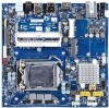
... Touch panel USB connector TV tuner USB connector Back Light switch Front panelconnector SATA cable connectors Hard disk power connector USB connector Audio cable connector CPU fan connector Intel LGA1155 socket System fan connector Flat Panel Display connector LVDS connector Digital Mic connector WEBCAM connector DDR3 SO-DIMM slot (channel B-1 ) DDR3...
... Touch panel USB connector TV tuner USB connector Back Light switch Front panelconnector SATA cable connectors Hard disk power connector USB connector Audio cable connector CPU fan connector Intel LGA1155 socket System fan connector Flat Panel Display connector LVDS connector Digital Mic connector WEBCAM connector DDR3 SO-DIMM slot (channel B-1 ) DDR3...
Manual
Page 7
...; Do not place the computer system in a high-temperature environment. • Turning on the computer power during the installation process can become damaged as a motherboard, CPU or memory.
...; Do not place the computer system in a high-temperature environment. • Turning on the computer power during the installation process can become damaged as a motherboard, CPU or memory.
Manual
Page 8
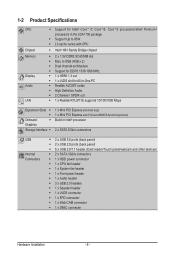
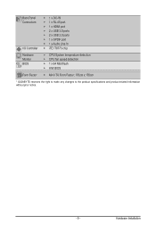
...; 5 x USB 2.0/1.1 header (Card reader/Touch panel/webcam and other devices) ŠŠ 2 x SATA 3Gb/s connectors ŠŠ 1 x HDD power connector ŠŠ 1 x CPU fan header ŠŠ 1 x System fan header ŠŠ 1 x Front panel header ŠŠ 1 x Audio header ŠŠ 3 x USB 2.0 headers ŠŠ ...x FPD connector ŠŠ 1 x Web CAM connector ŠŠ 1 x DMIC connector Hardware Installation - 8 - to 95W ŠŠ L3 cache varies with CPU ŠŠ Intel® H61 Sandy Bridge chipset ŠŠ 2 x 1.5V DDR3 SO-DIMM slot ŠŠ Max.
...; 5 x USB 2.0/1.1 header (Card reader/Touch panel/webcam and other devices) ŠŠ 2 x SATA 3Gb/s connectors ŠŠ 1 x HDD power connector ŠŠ 1 x CPU fan header ŠŠ 1 x System fan header ŠŠ 1 x Front panel header ŠŠ 1 x Audio header ŠŠ 3 x USB 2.0 headers ŠŠ ...x FPD connector ŠŠ 1 x Web CAM connector ŠŠ 1 x DMIC connector Hardware Installation - 8 - to 95W ŠŠ L3 cache varies with CPU ŠŠ Intel® H61 Sandy Bridge chipset ŠŠ 2 x 1.5V DDR3 SO-DIMM slot ŠŠ Max.
Manual
Page 9
... ŠŠ 2 x USB 2.0 ports ŠŠ 1 x SPDIF port ŠŠ 1 x Audio Line In ŠŠ iTE IT8773 chip Hardware Monitor BIOS ŠŠ CPU/System temperature detection ŠŠ CPU fan speed detection ŠŠ 1 x 64 Mbit flash ŠŠ AMI BIOS Form Factor ŠŠ Mini ITX Form Factor; 170cm x 170cm...
... ŠŠ 2 x USB 2.0 ports ŠŠ 1 x SPDIF port ŠŠ 1 x Audio Line In ŠŠ iTE IT8773 chip Hardware Monitor BIOS ŠŠ CPU/System temperature detection ŠŠ CPU fan speed detection ŠŠ 1 x 64 Mbit flash ŠŠ AMI BIOS Form Factor ŠŠ Mini ITX Form Factor; 170cm x 170cm...
Manual
Page 10
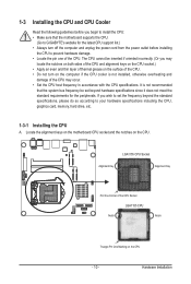
... not turn on the computer if the CPU cooler is not recommended that the motherboard supports the CPU. (Go to GIGABYTE's website for the peripherals. It is not installed, otherwise overheating and damage of the CPU Socket LGA1155 CPU Notch Notch Triangle Pin One Marking on the CPU. LGA1155 CPU Socket Alignment Key Alignment Key Pin One...
... not turn on the computer if the CPU cooler is not recommended that the motherboard supports the CPU. (Go to GIGABYTE's website for the peripherals. It is not installed, otherwise overheating and damage of the CPU Socket LGA1155 CPU Notch Notch Triangle Pin One Marking on the CPU. LGA1155 CPU Socket Alignment Key Alignment Key Pin One...
Manual
Page 11
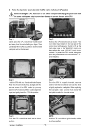
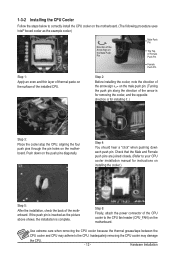
...inserted, use one corner of the load plate is not installed.) Step 3: Hold the CPU with your thumb to lift up the front edge (next to the CPU. Step 5: Push the CPU socket lever back into the motherboard CPU socket. Follow the steps below to lightly replace the load plate. NOTE: Hold the... to prevent damage to the "REMOVE" mark) and then remove the cover. (DO NOT touch socket contacts. Before installing the CPU, make sure the front end of the CPU socket (or you may align the CPU notches with the pin one hand to hold the socket lever and use your finger.
...inserted, use one corner of the load plate is not installed.) Step 3: Hold the CPU with your thumb to lift up the front edge (next to the CPU. Step 5: Push the CPU socket lever back into the motherboard CPU socket. Follow the steps below to lightly replace the load plate. NOTE: Hold the... to prevent damage to the "REMOVE" mark) and then remove the cover. (DO NOT touch socket contacts. Before installing the CPU, make sure the front end of the CPU socket (or you may align the CPU notches with the pin one hand to hold the socket lever and use your finger.
Manual
Page 12
... Hardware Installation Push down each push pin. Check that the Male and Female push pins are joined closely. (Refer to the CPU fan header (CPU_FAN) on installing the cooler.) Step 5: After the installation, check the back of the motherboard. Use extreme care when ...removing the CPU cooler because the thermal grease/tape between the CPU cooler and CPU may damage the CPU. - 12 - Inadequately removing the CPU cooler may adhere to correctly install the CPU cooler on the motherboard. (The following procedure uses Intel® ...
... Hardware Installation Push down each push pin. Check that the Male and Female push pins are joined closely. (Refer to the CPU fan header (CPU_FAN) on installing the cooler.) Step 5: After the installation, check the back of the motherboard. Use extreme care when ...removing the CPU cooler because the thermal grease/tape between the CPU cooler and CPU may damage the CPU. - 12 - Inadequately removing the CPU cooler may adhere to correctly install the CPU cooler on the motherboard. (The following procedure uses Intel® ...
Manual
Page 13
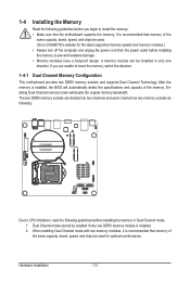
...The two DDR3 memory sockets are divided into two channels and each channel has two memory sockets as following: SODIMMB1 SODIMMA1 Due to CPU limitations, read the following guidelines before you are unable to prevent hardware damage. • Memory modules have a foolproof design. If ... to install the memory: • Make sure that memory of the same capacity, brand, speed, and chips be used . (Go to GIGABYTE's website for optimum performance. Enabling Dual Channel memory mode will automatically detect the specifications and capacity of the same capacity, brand, speed, and chips...
...The two DDR3 memory sockets are divided into two channels and each channel has two memory sockets as following: SODIMMB1 SODIMMA1 Due to CPU limitations, read the following guidelines before you are unable to prevent hardware damage. • Memory modules have a foolproof design. If ... to install the memory: • Make sure that memory of the same capacity, brand, speed, and chips be used . (Go to GIGABYTE's website for optimum performance. Enabling Dual Channel memory mode will automatically detect the specifications and capacity of the same capacity, brand, speed, and chips...
Manual
Page 22
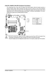
...insertion design. Overheating may hang. • These fan headers are not configuration jumper blocks. The motherboard supports CPU fan speed control, which requires the use of a CPU fan with fan speed control design. Do not place a jumper cap on the headers. For optimum heat ...dissipation, it in damage to prevent your CPU and system from overheating. Hardware Installation - 22 - 9/10) CPU_FAN/SYS_FAN (CPU Fan/System Fan Headers) The motherboard has a 4-pin CPU fan header (CPU_FAN) headers. SYS_FAN Pin No. When connecting a fan cable,...
...insertion design. Overheating may hang. • These fan headers are not configuration jumper blocks. The motherboard supports CPU fan speed control, which requires the use of a CPU fan with fan speed control design. Do not place a jumper cap on the headers. For optimum heat ...dissipation, it in damage to prevent your CPU and system from overheating. Hardware Installation - 22 - 9/10) CPU_FAN/SYS_FAN (CPU Fan/System Fan Headers) The motherboard has a 4-pin CPU fan header (CPU_FAN) headers. SYS_FAN Pin No. When connecting a fan cable,...
Manual
Page 32
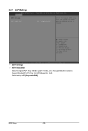
Suspend Disabled/S1 (CPU Stop Clock)/S3 (Suspend to RAM). Default setting is pressed. BIOS Setup - 32 - 2-2-1 ACPI Settings ACPI Settings ACPI Sleep State Select the highest ACPI sleep state the system will enter, when the suspend button is S3 (Suspend to RAM).
Suspend Disabled/S1 (CPU Stop Clock)/S3 (Suspend to RAM). Default setting is pressed. BIOS Setup - 32 - 2-2-1 ACPI Settings ACPI Settings ACPI Sleep State Select the highest ACPI sleep state the system will enter, when the suspend button is S3 (Suspend to RAM).
Manual
Page 33
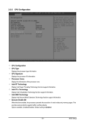
... processor core. This provides some protection against buffer overflow attacks. Intel HT Technology Display Intel Hyper Threading Technology function support information. Options available: Enabled/Disabled. CPU Signature Displays the processor ID information. Default setting is Enabled. - 33 - Intel SMX Technology Display Intel Secure Mode Extensions Technology function support information...
... processor core. This provides some protection against buffer overflow attacks. Intel HT Technology Display Intel Hyper Threading Technology function support information. Options available: Enabled/Disabled. CPU Signature Displays the processor ID information. Default setting is Enabled. - 33 - Intel SMX Technology Display Intel Secure Mode Extensions Technology function support information...

Manual
Page 34
... about Intel CPUs' unique features, please visit Intel's website. For more enhanced power-saving state than C1. CPU C3/C6 Support (Note) Allows you install a CPU that supports this setting. The C3/C6 state is ACPI C2. Auto lets the BIOS automatically configure this feature... information of Recommended short duration power limit. (Note) This item is Disabled. Options available for CPU C6 Report: Enabled/Disabled. BIOS Setup - 34 - Options available for CPU C3 Report: ACPI C2/ACPI C3/Disabled. Default setting is Enabled. Intel Virtualization Technology Select whether...
... about Intel CPUs' unique features, please visit Intel's website. For more enhanced power-saving state than C1. CPU C3/C6 Support (Note) Allows you install a CPU that supports this setting. The C3/C6 state is ACPI C2. Auto lets the BIOS automatically configure this feature... information of Recommended short duration power limit. (Note) This item is Disabled. Options available for CPU C6 Report: Enabled/Disabled. BIOS Setup - 34 - Options available for CPU C3 Report: ACPI C2/ACPI C3/Disabled. Default setting is Enabled. Intel Virtualization Technology Select whether...
Manual
Page 40
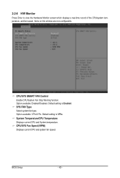
... Fan Stop Warning function. Option available: Enabled/Disabled. Option available: 3 Pin/4 Pin. CPU/SYS Fan Speed (RPM) Displays current CPU and system fan speed. SYS FAN Type Select system fan type. Default setting is 3 Pin. System Temperature/CPU Temperature Displays current CPU and System temperature. Default setting is Enabled. BIOS Setup - 40 - 2-2-6 H/W Monitor Press...
... Fan Stop Warning function. Option available: Enabled/Disabled. Option available: 3 Pin/4 Pin. CPU/SYS Fan Speed (RPM) Displays current CPU and system fan speed. SYS FAN Type Select system fan type. Default setting is 3 Pin. System Temperature/CPU Temperature Displays current CPU and System temperature. Default setting is Enabled. BIOS Setup - 40 - 2-2-6 H/W Monitor Press...


