Manual
Page 3
... Box Contents...4 MSH61DI Motherboard Layout 5 Chapter 1 Hardware Installation 7 1-1 Installation Precautions 7 1-2 Product Specifications 8 1-3 Installing the CPU and CPU Cooler 10 1-3-1 Installing the CPU...10 1-3-2 Installing the CPU Cooler 12 1-4 Installing the Memory 13 1-4-1 Dual Channel Memory Configuration 13 1-4-2 Installing a Memory 14 1-5 Back Panel Connectors 15 1-6 Internal Connectors 17 Chapter 2 BIOS Setup 27 2-1 The...
... Box Contents...4 MSH61DI Motherboard Layout 5 Chapter 1 Hardware Installation 7 1-1 Installation Precautions 7 1-2 Product Specifications 8 1-3 Installing the CPU and CPU Cooler 10 1-3-1 Installing the CPU...10 1-3-2 Installing the CPU Cooler 12 1-4 Installing the Memory 13 1-4-1 Dual Channel Memory Configuration 13 1-4-2 Installing a Memory 14 1-5 Back Panel Connectors 15 1-6 Internal Connectors 17 Chapter 2 BIOS Setup 27 2-1 The...
Manual
Page 9
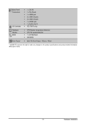
...; 1 x Audio Line In ŠŠ iTE IT8773 chip Hardware Monitor BIOS ŠŠ CPU/System temperature detection ŠŠ CPU fan speed detection ŠŠ 1 x 64 Mbit flash ŠŠ AMI BIOS Form Factor ŠŠ Mini ITX Form Factor; 170cm x 170cm * GIGABYTE reserves the right to make any changes to the product...
...; 1 x Audio Line In ŠŠ iTE IT8773 chip Hardware Monitor BIOS ŠŠ CPU/System temperature detection ŠŠ CPU fan speed detection ŠŠ 1 x 64 Mbit flash ŠŠ AMI BIOS Form Factor ŠŠ Mini ITX Form Factor; 170cm x 170cm * GIGABYTE reserves the right to make any changes to the product...
Manual
Page 13
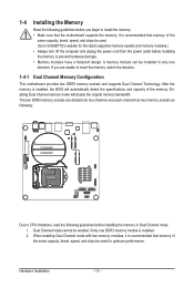
..., it is installed, the BIOS will double the original memory bandwidth. If you begin to prevent hardware damage. • Memory modules have a foolproof design. Hardware Installation - 13 - After the memory is recommended that memory of the same capacity, brand, speed, and chips be used . (Go to GIGABYTE's website for optimum performance. The...
..., it is installed, the BIOS will double the original memory bandwidth. If you begin to prevent hardware damage. • Memory modules have a foolproof design. Hardware Installation - 13 - After the memory is recommended that memory of the same capacity, brand, speed, and chips be used . (Go to GIGABYTE's website for optimum performance. The...
Manual
Page 15
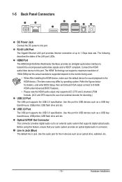
... port for decoding.) USB 2.0 Port The USB port supports the USB 2.0 specification. Use this port for details.), and enter BIOS Setup, then set Onboard VGA output connect to D-SUB/ HDMI under Advanced BIOS Features.. • Please note the HDMI audio output only supports AC3, DTS and 2-channel-LPCM formats. (AC3 and DTS...
... port for decoding.) USB 2.0 Port The USB port supports the USB 2.0 specification. Use this port for details.), and enter BIOS Setup, then set Onboard VGA output connect to D-SUB/ HDMI under Advanced BIOS Features.. • Please note the HDMI audio output only supports AC3, DTS and 2-channel-LPCM formats. (AC3 and DTS...
Manual
Page 26
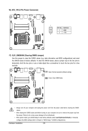
... on the two pins to temporarily short the two pins or use a metal object like a screwdriver to Chapter 2, "BIOS Setup," for a few seconds. date information and BIOS configurations) and reset the CMOS values to clear the CMOS values (e.g. Failure to do so may cause damage to the... motherboard. • After system restart, go to BIOS Setup to load factory defaults (select Load Optimized Defaults) or manually configure the BIOS settings (refer to touch the two pins for BIOS configurations). 16) ATX_19V (2 Pin Power Connector) 1 Pin No.
... on the two pins to temporarily short the two pins or use a metal object like a screwdriver to Chapter 2, "BIOS Setup," for a few seconds. date information and BIOS configurations) and reset the CMOS values to clear the CMOS values (e.g. Failure to do so may cause damage to the... motherboard. • After system restart, go to BIOS Setup to load factory defaults (select Load Optimized Defaults) or manually configure the BIOS settings (refer to touch the two pins for BIOS configurations). 16) ATX_19V (2 Pin Power Connector) 1 Pin No.
Manual
Page 27
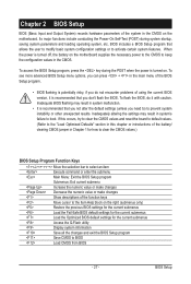
... current submenus Access the Q-Flash utility Display system information Save all the changes and exit the BIOS Setup program Save CMOS to BIOS Load CMOS from BIOS - 27 - BIOS includes a BIOS Setup program that you do it is recommended that allows the user to modify basic system configuration... settings or to the "Load Optimized Defaults" section in this chapter or introductions of using the current BIOS version, it with caution. To flash the BIOS, do not encounter problems of the battery/ clearing CMOS jumper in the CMOS on the motherboard. If this...
... current submenus Access the Q-Flash utility Display system information Save all the changes and exit the BIOS Setup program Save CMOS to BIOS Load CMOS from BIOS - 27 - BIOS includes a BIOS Setup program that you do it is recommended that allows the user to modify basic system configuration... settings or to the "Load Optimized Defaults" section in this chapter or introductions of using the current BIOS version, it with caution. To flash the BIOS, do not encounter problems of the battery/ clearing CMOS jumper in the CMOS on the motherboard. If this...
Manual
Page 28
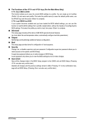
... The Functions of the and keys (For the Main Menu Only) F11: Save CMOS to BIOS This function allows you to save the current BIOS settings to the CMOS and exit BIOS Setup. (Pressing can also carry out this task.) Abandon all changes and the previous settings remain in effect.... A user password only allows you to 8 profiles (Profile 1-8) and name each profile. A supervisor password allows you to view the BIOS settings but not to make changes in the BIOS Setup program to a profile. You can create up to make changes. Save & Exit Save all the changes made in...
... The Functions of the and keys (For the Main Menu Only) F11: Save CMOS to BIOS This function allows you to save the current BIOS settings to the CMOS and exit BIOS Setup. (Pressing can also carry out this task.) Abandon all changes and the previous settings remain in effect.... A user password only allows you to 8 profiles (Profile 1-8) and name each profile. A supervisor password allows you to view the BIOS settings but not to make changes in the BIOS Setup program to a profile. You can create up to make changes. Save & Exit Save all the changes made in...
Manual
Page 29
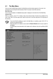
...Help) of the Main Menu. Press to display a help screen. Help for reference only and may differ by BIOS version. - 29 - BIOS Setup 2-1 The Main Menu Once you want in the Main Menu or a submenu, press + to access more...the menu. Use arrow keys to move among the items and press to its defaults. • The BIOS Setup menus described in this chapter are for each item is in the Item Help block on the right ...side of the submenu. • If you do not find the settings you enter the BIOS Setup program, the Main Menu (as usual, select the Restore Defaults item to set your system to ...
...Help) of the Main Menu. Press to display a help screen. Help for reference only and may differ by BIOS version. - 29 - BIOS Setup 2-1 The Main Menu Once you want in the Main Menu or a submenu, press + to access more...the menu. Use arrow keys to move among the items and press to its defaults. • The BIOS Setup menus described in this chapter are for each item is in the Item Help block on the right ...side of the submenu. • If you do not find the settings you enter the BIOS Setup program, the Main Menu (as usual, select the Restore Defaults item to set your system to ...
Manual
Page 30
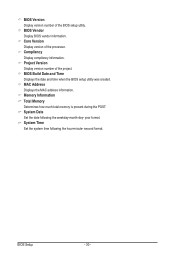
... version number of the project. System Time Set the system time following the weekday-month-day- BIOS Setup - 30 - Project Version Display version number of the BIOS setup utility. MAC Address Displays the MAC address information. Compliency Display compliency information. Core Version Display version of the processor. Memory ...how much total memory is present during the POST. second format. System Date Set the date following the hour-minute- year format. BIOS Vendor Display BIOS vendor information. BIOS Build Date and Time Displays the date and time when the...
... version number of the project. System Time Set the system time following the weekday-month-day- BIOS Setup - 30 - Project Version Display version number of the BIOS setup utility. MAC Address Displays the MAC address information. Compliency Display compliency information. Core Version Display version of the processor. Memory ...how much total memory is present during the POST. second format. System Date Set the date following the hour-minute- year format. BIOS Vendor Display BIOS vendor information. BIOS Build Date and Time Displays the date and time when the...
Manual
Page 31
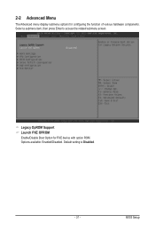
2-2 Advanced Menu The Advanced menu display submenu options for PXE device with option ROM. Legacy OpROM Support Launch PXE OPROM Enable/Disable Boot Option for configuring the function of various hardware components. BIOS Setup Options available: Enabled/Disabled. Select a submenu item, then press Enter to access the related submenu screen. Default setting is Disabled. - 31 -
2-2 Advanced Menu The Advanced menu display submenu options for PXE device with option ROM. Legacy OpROM Support Launch PXE OPROM Enable/Disable Boot Option for configuring the function of various hardware components. BIOS Setup Options available: Enabled/Disabled. Select a submenu item, then press Enter to access the related submenu screen. Default setting is Disabled. - 31 -
Manual
Page 32
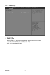
Default setting is pressed. 2-2-1 ACPI Settings ACPI Settings ACPI Sleep State Select the highest ACPI sleep state the system will enter, when the suspend button is S3 (Suspend to RAM). BIOS Setup - 32 - Suspend Disabled/S1 (CPU Stop Clock)/S3 (Suspend to RAM).
Default setting is pressed. 2-2-1 ACPI Settings ACPI Settings ACPI Sleep State Select the highest ACPI sleep state the system will enter, when the suspend button is S3 (Suspend to RAM). BIOS Setup - 32 - Suspend Disabled/S1 (CPU Stop Clock)/S3 (Suspend to RAM).
Manual
Page 33
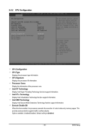
BIOS Setup Processor Cores Display the information of code in data-only memory pages. This provides some protection against buffer overflow attacks. Intel VT-x Technology Display ...
BIOS Setup Processor Cores Display the information of code in data-only memory pages. This provides some protection against buffer overflow attacks. Intel VT-x Technology Display ...

Manual
Page 34
Default setting is Enabled. Auto lets the BIOS automatically configure this feature. Options available for CPU C6 Report: Enabled/Disabled. For more enhanced power-saving state than C1. Display the information of Recommended ...short duration power limit. (Note) This item is present only if you to determine whether to decrease power consumption. Default setting is Disabled. BIOS Setup - 34 - When enabled, the CPU core frequency and voltage will be reduced during system halt state to let the CPU enter C3/C6 mode...
Default setting is Enabled. Auto lets the BIOS automatically configure this feature. Options available for CPU C6 Report: Enabled/Disabled. For more enhanced power-saving state than C1. Display the information of Recommended ...short duration power limit. (Note) This item is present only if you to determine whether to decrease power consumption. Default setting is Disabled. BIOS Setup - 34 - When enabled, the CPU core frequency and voltage will be reduced during system halt state to let the CPU enter C3/C6 mode...
Manual
Page 35
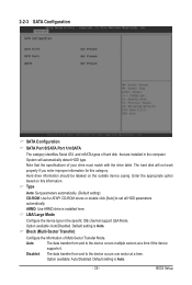
...] to set all HDD parameters automatically. Enter the appropriate option based on the outside device casing. Option available: Auto/Disabled. Default setting is installed here. BIOS Setup 2-2-3 SATA Configuration SATA Configuration SATA Port 0/SATA Port 1/mSATA The category identifies Serial ATA and mSATA types of hard disk that the specifications of...
...] to set all HDD parameters automatically. Enter the appropriate option based on the outside device casing. Option available: Auto/Disabled. Default setting is installed here. BIOS Setup 2-2-3 SATA Configuration SATA Configuration SATA Port 0/SATA Port 1/mSATA The category identifies Serial ATA and mSATA types of hard disk that the specifications of...
Manual
Page 36
... Slave drives) attached to that particular IDE channel. Default setting is Auto. 32Bit Data Transfer Configure the 32Bit Data Transfer rate. Option available: Auto/Disabled. BIOS Setup - 36 - Default setting is Auto. Default setting is Auto. Option available: Auto/Disabled.
... Slave drives) attached to that particular IDE channel. Default setting is Auto. 32Bit Data Transfer Configure the 32Bit Data Transfer rate. Option available: Auto/Disabled. BIOS Setup - 36 - Default setting is Auto. Default setting is Auto. Option available: Auto/Disabled.
Manual
Page 37
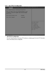
BIOS Setup Items on this window are non-configurable. - 37 - 2-2-4 Intel TXT(LT) Configuration Intel TXT(LT) Configuration The Intel Trusted Execution Technology (TXT) submenu is a display page for the Intel TXT information.
BIOS Setup Items on this window are non-configurable. - 37 - 2-2-4 Intel TXT(LT) Configuration Intel TXT(LT) Configuration The Intel Trusted Execution Technology (TXT) submenu is a display page for the Intel TXT information.
Manual
Page 38
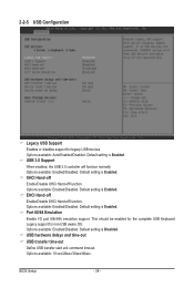
.... Default setting is Enabled. USB hardware delays and time-out USB transfer time-out Define USB transfer start unit command timeout. Default setting is Enabled. BIOS Setup - 38 - 2-2-5 USB Configuration Legacy USB Support Enables or disables support for non-USB aware OS. Options available: Auto/Enabled/Disabled. Options available: Enabled/Disabled...
.... Default setting is Enabled. USB hardware delays and time-out USB transfer time-out Define USB transfer start unit command timeout. Default setting is Enabled. BIOS Setup - 38 - 2-2-5 USB Configuration Legacy USB Support Enables or disables support for non-USB aware OS. Options available: Auto/Enabled/Disabled. Options available: Enabled/Disabled...

Manual
Page 39
Options available: 10 sec/20sec/30sec/40sec. Options available: Auto. (Note) This item is set to Manual, you attach USB types of device. - 39 - Options available: Auto/Manual. When this item is present only if you can press numeric keys to configure desired values. BIOS Setup Device reset time-out Define USB device reset start unit command timeout. Device power-up delay Define USB device powering up start unit command timeout. Mass Storage Device(Note) This BIOS feature determines if the USB flash drive be treated as a floppy disk drive or a hard drive.
Options available: 10 sec/20sec/30sec/40sec. Options available: Auto. (Note) This item is set to Manual, you attach USB types of device. - 39 - Options available: Auto/Manual. When this item is present only if you can press numeric keys to configure desired values. BIOS Setup Device reset time-out Define USB device reset start unit command timeout. Device power-up delay Define USB device powering up start unit command timeout. Mass Storage Device(Note) This BIOS feature determines if the USB flash drive be treated as a floppy disk drive or a hard drive.
Manual
Page 40
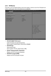
BIOS Setup - 40 - 2-2-6 H/W Monitor Press Enter to view the Hardware Monitor screen which displays a real-time record of the CPU/system temperature, and fan speed, Items ...
BIOS Setup - 40 - 2-2-6 H/W Monitor Press Enter to view the Hardware Monitor screen which displays a real-time record of the CPU/system temperature, and fan speed, Items ...
Manual
Page 41
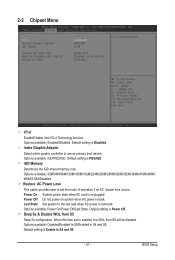
.... Default setting is removed. Default setting is Enable in S4 and S5. Default setting is Power Off. IGD Memory Determone the IGD shared memory size. BIOS Setup Options available: Disabled/Enabled in S5/Enabled in S4 and S5. - 41 - Default setting is PEG/IGD. Power On: System power state when AC...
.... Default setting is removed. Default setting is Enable in S4 and S5. Default setting is Power Off. IGD Memory Determone the IGD shared memory size. BIOS Setup Options available: Disabled/Enabled in S5/Enabled in S4 and S5. - 41 - Default setting is PEG/IGD. Power On: System power state when AC...


