Gigabyte MNIC8CI Support and Manuals
Get Help and Manuals for this Gigabyte item
View All Support Options Below
Free Gigabyte MNIC8CI manuals!
Problems with Gigabyte MNIC8CI?
Ask a Question
Free Gigabyte MNIC8CI manuals!
Problems with Gigabyte MNIC8CI?
Ask a Question
Popular Gigabyte MNIC8CI Manual Pages
Manual - Page 1

GA-D525E-C6
Intel® D525 Processor Motherboards
User's Manual
Rev. 1001
Manual - Page 2

... Quick Installation Guide included with the product. Changes to the specifications and features in this manual may be reproduced, copied, translated, transmitted, or published in this manual is protected by copyright laws and is the property of this manual are legally registered to assist in this manual may be made by any form or by GIGABYTE without GIGABYTE's prior...
Manual - Page 3

Table of Contents
GA-D525E-C6 Motherboard Layout 4 Chapter 1 Hardware Installation 6
1-1 Installation Precautions 6 1-2 Product Specifications 7 1-3 Installing the Memory 9
1-3-1 Installing a Memory ...9
1-4 Back Panel Connectors 10 1-5 Internal Connectors 12
- 3 -
Manual - Page 4

GA-D525E-C6 Motherboard Layout
1 2
3 4
5
6
41
40
39
38
37
36
v
35
34
33 32
31
30
29
28
27
7
8
43
9 42
10 41 11
12 13
14 15
16 17
18
19
20
26
25
24 23 22
21
- 4 -
Manual - Page 6
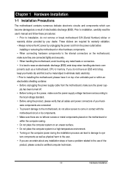
... sure the power supply voltage has been set according to
the local voltage standard. • Before using the product, please verify that all cables and power connectors of electrostatic discharge (ESD). tem components as well as a motherboard, CPU or memory.
Prior to installation, carefully read the user's manual and follow these procedures:
• Prior...
Manual - Page 9

...GIGABYTE's website for the latest supported memory speeds and memory modules.) • Always turn off the computer and unplug the power cord from the power outlet to prevent damage to install...into the DIM slot. Please note that the motherboard supports the memory. Step 3. 1-3 Installing the Memory
Read the following guidelines before installing the memory to prevent hardware damage. • ...
Manual - Page 11

... is occurring
• When removing the cable connected to a back panel connector, first remove the cable from your device and then remove it from the motherboard.
• When removing the cable, pull it side to side to prevent an electrical short inside the cable connector.
- 11 - Hardware...
Manual - Page 13

...power cord from the power outlet to prevent damage to the devices. • After installing the device and before connecting external devices: • First make sure the device ... devices and your devices are compliant with the connectors you wish to connect. • Before installing the devices, be sure to the connector on the computer, make sure your computer. Read the following guidelines ...
Manual - Page 14

... does not provide the required power, the result can supply enough stable power to all devices are properly installed.
To meet expansion requirements, it is turned off and all the components on the motherboard. Definition
1
3
1 GND
2 GND
2
4
3 +12V
4 +12V
2) VFD_JR1 (VFD & RS232 Mode Select Jumper)
1 5
2 6
VFD Mode RS232 Mode
VFD_JR1: 1-2, 3-5, 4-6 Close JCOM4...
Manual - Page 15

Hardware Installation Incorrect connection between the module connector and the motherboard header will make the device unable to this header.
Make sure the wire assignments of the module connector match the pin assignments of the motherboard header. 2) F_AUDIO (Front Panel Audio Header)
The front panel audio header supports Intel High Definition audio (HD) and AC...
Manual - Page 16

... 5 RED 6 GND 7 GREEN 8 DDC Clock 9 BLUE 10 DDC Data
- 16 -
The motherboard supports CPU fan speed control, which requires the use of a CPU fan with fan speed control design. ...headers possess a foolproof insertion design. Hardware Installation SYS_FAN 1
SYS_FAN1 1
CPU_FAN
SYS_FAN (System Fan):
Pin No. When connecting a fan cable, be installed inside the chassis. Overheating may result ...
Manual - Page 21

Hardware Installation
- 21 - 16/17/18) F_USB3/F_USB2/F_USB1 (USB Headers)
The headers conform to the F_USB1 header can provide two USB ports...+ NC GND GND No Pin NC
When the system is in S4/S5 mode, only the USB ports routed to USB 2.0/1.1 specification.
Each USB header can support the ON/OFF Charge function. For purchasing the optional USB bracket, please contact the local dealer.
Manual - Page 22

...(Or use a metal object like a screwdriver to replace the battery by removing the battery: 1. Hardware Installation COM4
COM1 COM5 COM3 COM6
1 9
2 10...BIOS configurations, date, and time information) in the power cord and restart your computer.
• Always turn off your computer and unplug the power cord before replacing the battery. • Replace the battery with an incorrect model...
Manual - Page 25

...Stand-by 5V
Hardware Installation
- 25 - Failure to do so may cause damage to the motherboard.
• After system restart, go to BIOS Setup to load factory defaults (select Load Optimized Defaults) or manually configure the BIOS settings (refer to factory defaults. date information and BIOS configurations) and reset the CMOS values to Chapter 2, "BIOS Setup," for a few seconds.
1
1-2 Close...
Manual - Page 26

34) LVDS_PWR1 (LVDS 3V/5V Select Jumper )
1
1-2 Close: 3.3V. (Default setting)
1
2-3 Close: 5V. Hardware Installati Pin No. 1 2 3
Definition 3.3V Power input 5V
- 26 -
Gigabyte MNIC8CI Reviews
We have not received any reviews for Gigabyte yet.