
Manual
Page 2
Motherboard GA-Z77X-UD4H Nov. 9, 2012 Motherboard GA-Z77X-UD4H Nov. 9, 2012
Motherboard GA-Z77X-UD4H Nov. 9, 2012 Motherboard GA-Z77X-UD4H Nov. 9, 2012
Manual
Page 3
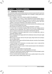
... the following types of documentations: „„ For quick set-up of GIGABYTE. Example: For product-related information, check on our website at: http://www.gigabyte.com Identifying Your Motherboard Revision The revision number on your motherboard revision before updating motherboard BIOS, drivers, or when looking for technical information. No part of this : "REV: X.X." Disclaimer...
... the following types of documentations: „„ For quick set-up of GIGABYTE. Example: For product-related information, check on our website at: http://www.gigabyte.com Identifying Your Motherboard Revision The revision number on your motherboard revision before updating motherboard BIOS, drivers, or when looking for technical information. No part of this : "REV: X.X." Disclaimer...

Manual
Page 4
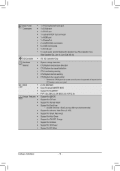
Table of Contents Box Contents...6 Optional Items...6 GA-Z77X-UD4H Motherboard Layout 7 GA-Z77X-UD4H Motherboard Block Diagram 8 Chapter 1 Hardware Installation 9 1-1 Installation Precautions 9 1-2 Product Specifications 10 1-3 Installing the CPU and CPU Cooler 14 1-3-1 Installing the CPU...14 1-3-2 Installing the CPU Cooler ...
Table of Contents Box Contents...6 Optional Items...6 GA-Z77X-UD4H Motherboard Layout 7 GA-Z77X-UD4H Motherboard Block Diagram 8 Chapter 1 Hardware Installation 9 1-1 Installation Precautions 9 1-2 Product Specifications 10 1-3 Installing the CPU and CPU Cooler 14 1-3-1 Installing the CPU...14 1-3-2 Installing the CPU Cooler ...

Manual
Page 6
The box contents are for reference only and the actual items shall depend on the product package you obtain. Box Contents 55 GA-Z77X-UD4H motherboard 55 Motherboard driver disk 55 User's Manual 55 Quick Installation Guide 55 Four SATA 6Gb/s cables 55 I/O Shield 55 One 2-Way SLI bridge connector The box contents ...
The box contents are for reference only and the actual items shall depend on the product package you obtain. Box Contents 55 GA-Z77X-UD4H motherboard 55 Motherboard driver disk 55 User's Manual 55 Quick Installation Guide 55 Four SATA 6Gb/s cables 55 I/O Shield 55 One 2-Way SLI bridge connector The box contents ...

Manual
Page 7
GA-Z77X-UD4H Motherboard Layout KB_MS_USB3 DVI VGA ATX_12V_2X4 CPU_FAN LGA1155 PW_SW CMOS_SW RST_SW VCORE CPUVTT VSA CPUPLL VDIMM DDRVTT PCHIO SYS_FAN2 DP_HDMI_SPDIF USB3_ESATA ATX USB30_LAN AUDIO VIA BAT VL800 Realtek GbE LAN PCIEX1_1 PCIEX16 GA-Z77X-UD4H DDR3_4 DDR3_2 DDR3_3 DDR3_1 F_USB30 ATX4P1 SATA3 1 0 CODEC PCIEX1_2 PCIEX1_3 PCIEX8 B_BIOS BBIOS_LED M_BIOS MBIOS_LED Marvell 88SE9172 Intel® Z77...
GA-Z77X-UD4H Motherboard Layout KB_MS_USB3 DVI VGA ATX_12V_2X4 CPU_FAN LGA1155 PW_SW CMOS_SW RST_SW VCORE CPUVTT VSA CPUPLL VDIMM DDRVTT PCHIO SYS_FAN2 DP_HDMI_SPDIF USB3_ESATA ATX USB30_LAN AUDIO VIA BAT VL800 Realtek GbE LAN PCIEX1_1 PCIEX16 GA-Z77X-UD4H DDR3_4 DDR3_2 DDR3_3 DDR3_1 F_USB30 ATX4P1 SATA3 1 0 CODEC PCIEX1_2 PCIEX1_3 PCIEX8 B_BIOS BBIOS_LED M_BIOS MBIOS_LED Marvell 88SE9172 Intel® Z77...

Manual
Page 8
GA-Z77X-UD4H Motherboard Block Diagram PCIe CLK (100 MHz) 1 PCI Express x16 or 2 PCI Express x8 LGA1155 CPU CPU CLK+/- (100 MHz) DDR3 1600/1333/1066 MHz Dual ...
GA-Z77X-UD4H Motherboard Block Diagram PCIe CLK (100 MHz) 1 PCI Express x16 or 2 PCI Express x8 LGA1155 CPU CPU CLK+/- (100 MHz) DDR3 1600/1333/1066 MHz Dual ...
Manual
Page 9
... verify that all cables and power connectors of your hardware components are connected. •• To prevent damage to the motherboard, do not have an ESD wrist strap, keep your dealer. Hardware Installation Prior to installation, carefully read the user's ...eliminate static electricity. •• Prior to installing the motherboard, please have a problem related to system components as well as a motherboard, CPU or memory. Chapter 1 Hardware Installation 1-1 Installation Precautions The motherboard contains numerous delicate electronic circuits and components which can lead ...
... verify that all cables and power connectors of your hardware components are connected. •• To prevent damage to the motherboard, do not have an ESD wrist strap, keep your dealer. Hardware Installation Prior to installation, carefully read the user's ...eliminate static electricity. •• Prior to installing the motherboard, please have a problem related to system components as well as a motherboard, CPU or memory. Chapter 1 Hardware Installation 1-1 Installation Precautions The motherboard contains numerous delicate electronic circuits and components which can lead ...
Manual
Page 12
... for Auto Green Support for ON/OFF Charge Support for Q-Share Support for 3D Power Support for EasyTune * Available functions in EasyTune may differ by motherboard model. Back Panel Connectors ŠŠ 1 x PS/2 keyboard/mouse port ŠŠ 1 x D-Sub port ŠŠ 1 x DVI-D port ŠŠ 1 x optical S/PDIF Out connector Š...
... for Auto Green Support for ON/OFF Charge Support for Q-Share Support for 3D Power Support for EasyTune * Available functions in EasyTune may differ by motherboard model. Back Panel Connectors ŠŠ 1 x PS/2 keyboard/mouse port ŠŠ 1 x D-Sub port ŠŠ 1 x DVI-D port ŠŠ 1 x optical S/PDIF Out connector Š...
Manual
Page 14
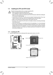
Locate the alignment keys on the motherboard CPU socket and the notches on the CPU Hardware Installation - 14 - If you may occur. •• Set the CPU host frequency in accordance with ... requirements for the latest CPU support list.) •• Always turn on the computer if the CPU cooler is not recommended that the motherboard supports the CPU. (Go to GIGABYTE's website for the peripherals. It is not installed, otherwise overheating and damage of the CPU may locate the notches on both sides...
Locate the alignment keys on the motherboard CPU socket and the notches on the CPU Hardware Installation - 14 - If you may occur. •• Set the CPU host frequency in accordance with ... requirements for the latest CPU support list.) •• Always turn on the computer if the CPU cooler is not recommended that the motherboard supports the CPU. (Go to GIGABYTE's website for the peripherals. It is not installed, otherwise overheating and damage of the CPU may locate the notches on both sides...
Manual
Page 15
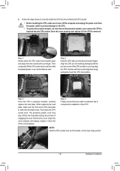
.... Hardware Installation Save the cover properly and replace it when the CPU is removed. B. Follow the steps below to correctly install the CPU into the motherboard CPU socket. •• Before installing the CPU, make sure the front end of the load plate is under its retention tab to turn off...
.... Hardware Installation Save the cover properly and replace it when the CPU is removed. B. Follow the steps below to correctly install the CPU into the motherboard CPU socket. •• Before installing the CPU, make sure the front end of the load plate is under its retention tab to turn off...

Manual
Page 16
...removing the CPU cooler may adhere to the CPU. 1-3-2 Installing the CPU Cooler Follow the steps below to correctly install the CPU cooler on the motherboard. (The following procedure uses Intel® boxed cooler as the picture above shows, the installation is to install.) Step 3: Place the cooler ... on the surface of arrow is to remove the cooler, on the contrary, is complete. Step 6: Finally, attach the power connector of the motherboard. Check that the Male and Female push pins are joined closely. (Refer to your CPU cooler installation manual for instructions on installing the cooler.)...
...removing the CPU cooler may adhere to the CPU. 1-3-2 Installing the CPU Cooler Follow the steps below to correctly install the CPU cooler on the motherboard. (The following procedure uses Intel® boxed cooler as the picture above shows, the installation is to install.) Step 3: Place the cooler ... on the surface of arrow is to remove the cooler, on the contrary, is complete. Step 6: Finally, attach the power connector of the motherboard. Check that the Male and Female push pins are joined closely. (Refer to your CPU cooler installation manual for instructions on installing the cooler.)...
Manual
Page 17
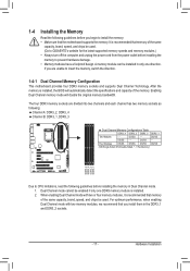
... following guidelines before installing the memory to prevent hardware damage. •• Memory modules have a foolproof design. It is recommended that the motherboard supports the memory. DS/SS - - For optimum performance, when enabling Dual Channel mode with two or four memory modules, it is recommended...install the memory: •• Make sure that memory of the same capacity, brand, speed, and chips be used . (Go to GIGABYTE's website for the latest supported memory speeds and memory modules.) •• Always turn off the computer and unplug the power cord from...
... following guidelines before installing the memory to prevent hardware damage. •• Memory modules have a foolproof design. It is recommended that the motherboard supports the memory. DS/SS - - For optimum performance, when enabling Dual Channel mode with two or four memory modules, it is recommended...install the memory: •• Make sure that memory of the same capacity, brand, speed, and chips be used . (Go to GIGABYTE's website for the latest supported memory speeds and memory modules.) •• Always turn off the computer and unplug the power cord from...
Manual
Page 18
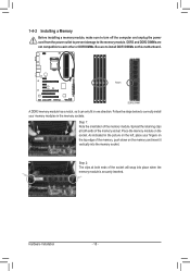
... socket. As indicated in the picture on the memory and insert it can only fit in the memory sockets. Place the memory module on this motherboard. Notch DDR3 DIMM A DDR3 memory module has a notch, so it vertically into place when the memory module is securely inserted. Follow the steps below to...
... socket. As indicated in the picture on the memory and insert it can only fit in the memory sockets. Place the memory module on this motherboard. Notch DDR3 DIMM A DDR3 memory module has a notch, so it vertically into place when the memory module is securely inserted. Follow the steps below to...
Manual
Page 19
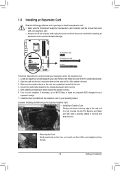
... off the computer and unplug the power cord from the power outlet before you begin to install an expansion card: •• Make sure the motherboard supports the expansion card. Make sure the metal contacts on the card are completely inserted into the PCI Express slot. After installing all expansion cards...
... off the computer and unplug the power cord from the power outlet before you begin to install an expansion card: •• Make sure the motherboard supports the expansion card. Make sure the metal contacts on the card are completely inserted into the PCI Express slot. After installing all expansion cards...
Manual
Page 20
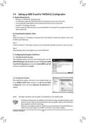
... the Set SLI and Physx Configuration screen and ensure Maximize 3D performance is selected and click Apply. Configuring the Graphics Card Driver C-1. A CrossFire/SLI-supported motherboard with two PCI Express x16 slots and correct driver -- To Enable SLI Function After installing the graphics card driver in the operating system, go to...
... the Set SLI and Physx Configuration screen and ensure Maximize 3D performance is selected and click Apply. Configuring the Graphics Card Driver C-1. A CrossFire/SLI-supported motherboard with two PCI Express x16 slots and correct driver -- To Enable SLI Function After installing the graphics card driver in the operating system, go to...

Manual
Page 21
.... It also supports up to the DVI-D specificationand supports a maximum resolution of transmitting uncompressed audio/video signals. Do not rock it straight out from the motherboard. •• When removing the cable, pull it side to side to this port. Connect a monitor that supports digital optical audio. The maximum supported resolution...
.... It also supports up to the DVI-D specificationand supports a maximum resolution of transmitting uncompressed audio/video signals. Do not rock it straight out from the motherboard. •• When removing the cable, pull it side to side to this port. Connect a monitor that supports digital optical audio. The maximum supported resolution...
Manual
Page 22
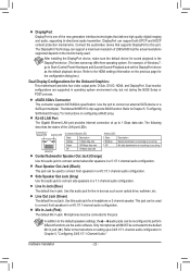
... audio configuration in jack ( ). Line In Jack (Blue) The default line in jack. Refer to Chapter 5, "Configuring SATA Hard Drive(s)," for the Onboard Graphics: This motherboard provides four video output ports: D-Sub, DVI-D, HDMI, and DisplayPort. Refer to the HDMI settings information on setting up to perform different functions via the...
... audio configuration in jack ( ). Line In Jack (Blue) The default line in jack. Refer to Chapter 5, "Configuring SATA Hard Drive(s)," for the Onboard Graphics: This motherboard provides four video output ports: D-Sub, DVI-D, HDMI, and DisplayPort. Refer to the HDMI settings information on setting up to perform different functions via the...
Manual
Page 24
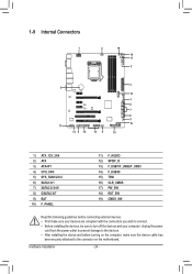
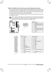
...) SPDIF_O 13) F_USB1/F_USB2/F_USB3 14) F_USB30 15) TPM 16) CLR_CMOS 17) PW_SW 18) RST_SW 19) CMOS_SW Read the following guidelines before turning on the motherboard. Unplug the power cord from the power outlet to prevent damage to the devices. •• After installing the device and before connecting external devices...
...) SPDIF_O 13) F_USB1/F_USB2/F_USB3 14) F_USB30 15) TPM 16) CLR_CMOS 17) PW_SW 18) RST_SW 19) CMOS_SW Read the following guidelines before turning on the motherboard. Unplug the power cord from the power outlet to prevent damage to the devices. •• After installing the device and before connecting external devices...
Manual
Page 25
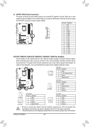
... are properly installed. Connect the power supply cable to the CPU. To meet expansion requirements, it is turned off and all the components on the motherboard. Before connecting the power connector, first make sure the power supply is recommended that a power supply that does not provide the required power, the result...
... are properly installed. Connect the power supply cable to the CPU. To meet expansion requirements, it is turned off and all the components on the motherboard. Before connecting the power connector, first make sure the power supply is recommended that a power supply that does not provide the required power, the result...
Manual
Page 26
... (the black connector wire is recommended that a system fan be sure to connect it is the ground wire). Do not place a jumper cap on this motherboard are not configuration jumper blocks. Hardware Installation - 26 - BIOS Switcher (X58A-OC) 1 M_SATA F_PANEL(NH) PWM Switch (X58A-OC) DIP 1 23 PCIe power connector (SATA...
... (the black connector wire is recommended that a system fan be sure to connect it is the ground wire). Do not place a jumper cap on this motherboard are not configuration jumper blocks. Hardware Installation - 26 - BIOS Switcher (X58A-OC) 1 M_SATA F_PANEL(NH) PWM Switch (X58A-OC) DIP 1 23 PCIe power connector (SATA...


