Manual
Page 3
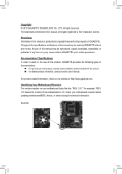
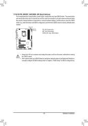
...For product-related information, check on our website at: http://www.gigabyte.com Identifying Your Motherboard Revision The revision number on your motherboard revision before updating motherboard BIOS, drivers, or when looking for technical information. Check your motherboard looks... like this manual may be made by GIGABYTE without GIGABYTE's prior written permission. All rights reserved. For example, ...
...For product-related information, check on our website at: http://www.gigabyte.com Identifying Your Motherboard Revision The revision number on your motherboard revision before updating motherboard BIOS, drivers, or when looking for technical information. Check your motherboard looks... like this manual may be made by GIGABYTE without GIGABYTE's prior written permission. All rights reserved. For example, ...

Manual
Page 4
Table of Contents Box Contents...6 Optional Items...6 GA-Z77X-UD4H Motherboard Layout 7 GA-Z77X-UD4H Motherboard Block Diagram 8 Chapter 1 Hardware Installation 9 1-1 Installation Precautions 9 1-2 Product Specifications 10 1-3 Installing the CPU and CPU Cooler ...20 1-7 Back Panel Connectors 21 1-8 Onboard Buttons, Switches and LEDs 23 1-9 Internal Connectors 24 Chapter 2 BIOS Setup 35 2-1 Startup Screen 36 2-2 The Main Menu 37 2-3 M.I.T...39 2-4 System...51 2-5 BIOS Features 52 2-6 Peripherals...55 2-7 Power Management 59 2-8 Save & Exit...61 Chapter 3 Drivers Installation 63 3-1...
Table of Contents Box Contents...6 Optional Items...6 GA-Z77X-UD4H Motherboard Layout 7 GA-Z77X-UD4H Motherboard Block Diagram 8 Chapter 1 Hardware Installation 9 1-1 Installation Precautions 9 1-2 Product Specifications 10 1-3 Installing the CPU and CPU Cooler ...20 1-7 Back Panel Connectors 21 1-8 Onboard Buttons, Switches and LEDs 23 1-9 Internal Connectors 24 Chapter 2 BIOS Setup 35 2-1 Startup Screen 36 2-2 The Main Menu 37 2-3 M.I.T...39 2-4 System...51 2-5 BIOS Features 52 2-6 Peripherals...55 2-7 Power Management 59 2-8 Save & Exit...61 Chapter 3 Drivers Installation 63 3-1...
Manual
Page 5
3-6 Download Center 66 3-7 New Program 66 Chapter 4 Unique Features 67 4-1 BIOS Update Utilities 67 4-1-1 Updating the BIOS with the Q-Flash Utility 67 4-1-2 Updating the BIOS with the @BIOS Utility 70 4-2 EasyTune 6...71 4-3 Q-Share...72 4-4 Smart Recovery 2 73 4-5 eXtreme Hard Drive (X.H.D 75 4-6 Auto Green...76 4-7 EZ Setup...77 4-7-1 Installing EZ Smart Response 78 4-7-2 Installing ...
3-6 Download Center 66 3-7 New Program 66 Chapter 4 Unique Features 67 4-1 BIOS Update Utilities 67 4-1-1 Updating the BIOS with the Q-Flash Utility 67 4-1-2 Updating the BIOS with the @BIOS Utility 70 4-2 EasyTune 6...71 4-3 Q-Share...72 4-4 Smart Recovery 2 73 4-5 eXtreme Hard Drive (X.H.D 75 4-6 Auto Green...76 4-7 EZ Setup...77 4-7-1 Installing EZ Smart Response 78 4-7-2 Installing ...

Manual
Page 8
GA-Z77X-UD4H Motherboard Block Diagram PCIe CLK (100 MHz) 1 PCI Express x16 or 2 PCI Express x8 LGA1155 CPU CPU CLK+/- (100 MHz) DDR3 1600/1333/1066 MHz ... or x4 x1 Switch LAN RJ45 Realtek GbE LAN x1 PCI Express Bus PCIe CLK (100 MHz) x1 PCIe to PCI Bridge PCI Bus Dual BIOS DMI 2.0 FDI Intel® Z77 2 eSATA 6Gb/s 2 SATA 6Gb/s or 4 USB 3.0/2.0 Switch VIA VL800 x1 Marvell 88SE9172 x1 PCI Express Bus D-Sub DisplayPort DVI-D HDMI...
GA-Z77X-UD4H Motherboard Block Diagram PCIe CLK (100 MHz) 1 PCI Express x16 or 2 PCI Express x8 LGA1155 CPU CPU CLK+/- (100 MHz) DDR3 1600/1333/1066 MHz ... or x4 x1 Switch LAN RJ45 Realtek GbE LAN x1 PCI Express Bus PCIe CLK (100 MHz) x1 PCIe to PCI Bridge PCI Bus Dual BIOS DMI 2.0 FDI Intel® Z77 2 eSATA 6Gb/s 2 SATA 6Gb/s or 4 USB 3.0/2.0 Switch VIA VL800 x1 Marvell 88SE9172 x1 PCI Express Bus D-Sub DisplayPort DVI-D HDMI...

Manual
Page 11
... panel audio header 1 x S/PDIF Out header 1 x USB 3.0/2.0 header 3 x USB 2.0/1.1 headers 1 x Clear CMOS jumper 1 x Trusted Platform Module (TPM) header 1 x power button 1 x reset button 1 x Clear CMOS button 1 x BIOS switch button Voltage Measurement Points - 11 - Support for using the eSATA connectors. Refer to 2 SATA 6Gb/s devices - Storage Interface ŠŠ ŠŠ USB Š...
... panel audio header 1 x S/PDIF Out header 1 x USB 3.0/2.0 header 3 x USB 2.0/1.1 headers 1 x Clear CMOS jumper 1 x Trusted Platform Module (TPM) header 1 x power button 1 x reset button 1 x Clear CMOS button 1 x BIOS switch button Voltage Measurement Points - 11 - Support for using the eSATA connectors. Refer to 2 SATA 6Gb/s devices - Storage Interface ŠŠ ŠŠ USB Š...
Manual
Page 12
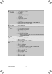
...In) I/O Controller ŠŠ iTE I/O Controller Chip Hardware ŠŠ Monitor ŠŠ ŠŠ ŠŠ ŠŠ ŠŠ BIOS ŠŠ ŠŠ ŠŠ ŠŠ Unique Features ŠŠ ŠŠ ŠŠ ŠŠ System voltage detection CPU...on the CPU/system cooler you install. 2 x 64 Mbit flash Use of licensed AMI EFI BIOS Support for DualBIOS™ PnP 1.0a, DMI 2.0, SM BIOS 2.6, ACPI 2.0a Support for @BIOS Support for Q-Flash Support for Xpress Install Support for EZ Setup Hardware Installation - 12 - ...
...In) I/O Controller ŠŠ iTE I/O Controller Chip Hardware ŠŠ Monitor ŠŠ ŠŠ ŠŠ ŠŠ ŠŠ BIOS ŠŠ ŠŠ ŠŠ ŠŠ Unique Features ŠŠ ŠŠ ŠŠ ŠŠ System voltage detection CPU...on the CPU/system cooler you install. 2 x 64 Mbit flash Use of licensed AMI EFI BIOS Support for DualBIOS™ PnP 1.0a, DMI 2.0, SM BIOS 2.6, ACPI 2.0a Support for @BIOS Support for Q-Flash Support for Xpress Install Support for EZ Setup Hardware Installation - 12 - ...
Manual
Page 17
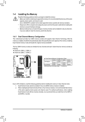
...Dual Channel mode with two memory modules, we recommend that memory of the same capacity, brand, speed, and chips be used . (Go to GIGABYTE's website for the latest supported memory speeds and memory modules.) •• Always turn off the computer and unplug the power cord from the ...detect the specifications and capacity of the same capacity, brand, speed, and chips be enabled if only one direction. It is installed, the BIOS will double the original memory bandwidth. For optimum performance, when enabling Dual Channel mode with two or four memory modules, it is installed. ...
...Dual Channel mode with two memory modules, we recommend that memory of the same capacity, brand, speed, and chips be used . (Go to GIGABYTE's website for the latest supported memory speeds and memory modules.) •• Always turn off the computer and unplug the power cord from the ...detect the specifications and capacity of the same capacity, brand, speed, and chips be enabled if only one direction. It is installed, the BIOS will double the original memory bandwidth. For optimum performance, when enabling Dual Channel mode with two or four memory modules, it is installed. ...
Manual
Page 19
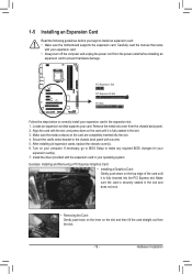
...contacts on the top edge of the card until it is fully inserted into the slot. 4. Secure the card's metal bracket to make any required BIOS changes for your expansion card(s). 7. Locate an expansion slot that came with the expansion card in the slot and does not rock. ••...outlet before you begin to correctly install your computer. Make sure the card is fully seated in the expansion slot. 1. If necessary, go to BIOS Setup to the chassis back panel with the slot, and press down on the card are completely inserted into the PCI Express slot. 1-5 Installing ...
...contacts on the top edge of the card until it is fully inserted into the slot. 4. Secure the card's metal bracket to make any required BIOS changes for your expansion card(s). 7. Locate an expansion slot that came with the expansion card in the slot and does not rock. ••...outlet before you begin to correctly install your computer. Make sure the card is fully seated in the expansion slot. 1. If necessary, go to BIOS Setup to the chassis back panel with the slot, and press down on the card are completely inserted into the PCI Express slot. 1-5 Installing ...
Manual
Page 22
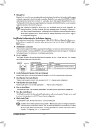
... connect front speakers in jack ( ). In addition to the default speakers settings, the ~ audio jacks can support a maximum resolution of 2560x1600 but not during the BIOS Setup or POST process. Refer to the HDMI settings information on configuring a RAID array. Use this audio jack to connect center/subwoofer speakers in a 7.1-channel...
... connect front speakers in jack ( ). In addition to the default speakers settings, the ~ audio jacks can support a maximum resolution of 2560x1600 but not during the BIOS Setup or POST process. Refer to the HDMI settings information on configuring a RAID array. Use this audio jack to connect center/subwoofer speakers in a 7.1-channel...

Manual
Page 23
...DIP 1 23 1 23 DIP Voltage Measurement Points TPM w/housing VoltDagBe_PmOeRasTurement module(X58A-OC) PCIe power connector (SATA)(X58A-OC) 1 BIOS S1w2it3cher (X58A-OC) PWM1 SDwIPitch (X58A-OC) 1 M_SATA 1 23 DIP DDIIPP 11 22 33 PCIe power connector (SATA)(X58A...1 23 1 Users can use a multimeter to measPuCrIee pocwoermcopnnoecntoer (nSAtTAv)o(Xl5t8aA-gOeC)s. F_PANEL(NH) F_UBSIBO30S Switch: SW4 F_AUDIO(H) F_USB30 1: Main BIOS (Boot from tDFh_BeA_UPmDOIROaT(iHn) BIOS) 1 F_PANEL(NH) BIOS Switcher (X58A-OC) F_PANEL(NH) 1 TPM DIP w/housing 1 23 DIP 1 23 DIP 1 1 23 DIP 1 1 23 DIP ...
...DIP 1 23 1 23 DIP Voltage Measurement Points TPM w/housing VoltDagBe_PmOeRasTurement module(X58A-OC) PCIe power connector (SATA)(X58A-OC) 1 BIOS S1w2it3cher (X58A-OC) PWM1 SDwIPitch (X58A-OC) 1 M_SATA 1 23 DIP DDIIPP 11 22 33 PCIe power connector (SATA)(X58A...1 23 1 Users can use a multimeter to measPuCrIee pocwoermcopnnoecntoer (nSAtTAv)o(Xl5t8aA-gOeC)s. F_PANEL(NH) F_UBSIBO30S Switch: SW4 F_AUDIO(H) F_USB30 1: Main BIOS (Boot from tDFh_BeA_UPmDOIROaT(iHn) BIOS) 1 F_PANEL(NH) BIOS Switcher (X58A-OC) F_PANEL(NH) 1 TPM DIP w/housing 1 23 DIP 1 23 DIP 1 1 23 DIP 1 1 23 DIP ...
Manual
Page 26
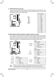
BIOS Switcher (X58A-OC) 1 M_SATA F_PANEL(NH) PWM Switch (X58A-OC) DIP 1 23 PCIe power connector (SATA)(X58A-OC) DIP 1 23 1 DIP 1 23 1 3) ATX4P1 (PCIe Power ... Control 1 SYS_FAN4 SYS_FAN4: Pin No. Most fan headers possess a foolproof insertion design. Do not place a jumper cap on this motherboard are 4-pin. Definition 1 NC 2 NC BIOS Switcher (SW4) 1 3 NC 4 GND 5 GND 6 GND 15 7 VCC 8 VCC 9 VCC DB_PORT 10 GND 11 GND 12 GND 13 +12V 14 +12V 15 +12V F_AUDIO(H) Voltage...
BIOS Switcher (X58A-OC) 1 M_SATA F_PANEL(NH) PWM Switch (X58A-OC) DIP 1 23 PCIe power connector (SATA)(X58A-OC) DIP 1 23 1 DIP 1 23 1 3) ATX4P1 (PCIe Power ... Control 1 SYS_FAN4 SYS_FAN4: Pin No. Most fan headers possess a foolproof insertion design. Do not place a jumper cap on this motherboard are 4-pin. Definition 1 NC 2 NC BIOS Switcher (SW4) 1 3 NC 4 GND 5 GND 6 GND 15 7 VCC 8 VCC 9 VCC DB_PORT 10 GND 11 GND 12 GND 13 +12V 14 +12V 15 +12V F_AUDIO(H) Voltage...
Manual
Page 28
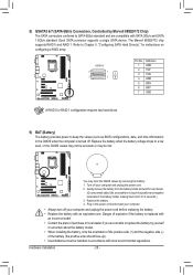
... TXN GND RXN RXP GND A RAID 0 or RAID 1 configuration requires two hard drives. 9) BAT (Battery) The battery provides power to keep the values (such as BIOS configurations, date, and time information) in accordance with SATA 3Gb/s and SATA 1.5Gb/s standard.
... TXN GND RXN RXP GND A RAID 0 or RAID 1 configuration requires two hard drives. 9) BAT (Battery) The battery provides power to keep the values (such as BIOS configurations, date, and time information) in accordance with SATA 3Gb/s and SATA 1.5Gb/s standard.
Manual
Page 29
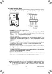
...; PW (Power Switch, Red): Connects to the power switch on the chassis front panel. When connecting your system using the power switch (refer to Chapter 2, "BIOS Setup," "Power Management," for more information). •• SPEAK (Speaker, Orange): Connects to the reset switch on the chassis front panel. Note the positive and...
...; PW (Power Switch, Red): Connects to the power switch on the chassis front panel. When connecting your system using the power switch (refer to Chapter 2, "BIOS Setup," "Power Management," for more information). •• SPEAK (Speaker, Orange): Connects to the reset switch on the chassis front panel. Note the positive and...

Manual
Page 30
...10 GND 10 NC DIP 1 23 1 DB_PO•R•T The front panel audio headBIeOrSsSuwpitpchoerrts(XH58DA-OaCu)dio by expansion (GA-IVB) carPdCsIe) pfoowredricgointanelcatourd(SioAToAu)(Xtp5u8At -fOroCm) your chassis front panel audio module to your expansion card. Voltage me•a&#... make the device unable to Chapter 5, "Configuring 2/4/5.1/7.1-Channel Audio." Definition oltage measurement points(G1.Sniper 3) BIOS Switcher (SW4) 1 1 SPDIFO 2 GND XDP_CPU XDP_PCH (GA-IVB) Hardware Installation - 30 - Make sure the wire assignments of the module connector match the pin ...
...10 GND 10 NC DIP 1 23 1 DB_PO•R•T The front panel audio headBIeOrSsSuwpitpchoerrts(XH58DA-OaCu)dio by expansion (GA-IVB) carPdCsIe) pfoowredricgointanelcatourd(SioAToAu)(Xtp5u8At -fOroCm) your chassis front panel audio module to your expansion card. Voltage me•a&#... make the device unable to Chapter 5, "Configuring 2/4/5.1/7.1-Channel Audio." Definition oltage measurement points(G1.Sniper 3) BIOS Switcher (SW4) 1 1 SPDIFO 2 GND XDP_CPU XDP_PCH (GA-IVB) Hardware Installation - 30 - Make sure the wire assignments of the module connector match the pin ...
Manual
Page 31
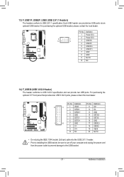
...SSTX2+ 5 SSTX1- DB_PORT15 SSTX2- 6 SSTX1+ 16 GND 20 7 GND 17 SSRX2+ 8 D1- 18 SSRX2- 9 D1+ 19 VBUS 10 NC Voltage meas2u0rementNmoodPuilne(X58A-OC) BIOS Switcher (X58A-O 1 PWM Switch (X58A-O DIP 1 23 1 DIP 1 23 1 •• Do not plug the IEEE 1394 bracket (2x5-pin) cable into the...provide two USB ports via an UG T optional USB bracket. Pin No. DIP 1 23 1 10 1 TPM w/housing Pin No. Hardware Installation BIOS Switcher (SW4) Each USB header can provide two USB ports. For purchasing the optional USB bracket, please contact the local dealer. For purchasing the...
...SSTX2+ 5 SSTX1- DB_PORT15 SSTX2- 6 SSTX1+ 16 GND 20 7 GND 17 SSRX2+ 8 D1- 18 SSRX2- 9 D1+ 19 VBUS 10 NC Voltage meas2u0rementNmoodPuilne(X58A-OC) BIOS Switcher (X58A-O 1 PWM Switch (X58A-O DIP 1 23 1 DIP 1 23 1 •• Do not plug the IEEE 1394 bracket (2x5-pin) cable into the...provide two USB ports via an UG T optional USB bracket. Pin No. DIP 1 23 1 10 1 TPM w/housing Pin No. Hardware Installation BIOS Switcher (SW4) Each USB header can provide two USB ports. For purchasing the optional USB bracket, please contact the local dealer. For purchasing the...
Manual
Page 32
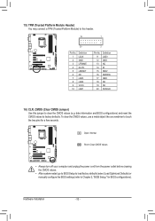
...load factory defaults (select Load Optimized Defaults) or manually configure the BIOS settings (refer to factory defaults. Hardware Installation - 32 - date information and BIOS configurations) and reset the CMOS values to Chapter 2, "BIOS Setup," for a few seconds. To clear the CMOS values, ... LAD3 17 GND LAD2 18 NC VCC3 19 NC LAD1 20 SUSCLK Voltage measurement points(G1.Sniper 3) BIOS Switcher (SW4) PWM Swi DIP 1 23 DIP 16) CLR_CMOS (Clear CMOS Jumper) Use this header. DB_PORT BIOS Switc 1 1 19 TPM w/housing 20 1 Voltage measurement module(X58A-OC) 2 Pin No. 1 2 3...
...load factory defaults (select Load Optimized Defaults) or manually configure the BIOS settings (refer to factory defaults. Hardware Installation - 32 - date information and BIOS configurations) and reset the CMOS values to Chapter 2, "BIOS Setup," for a few seconds. To clear the CMOS values, ... LAD3 17 GND LAD2 18 NC VCC3 19 NC LAD1 20 SUSCLK Voltage measurement points(G1.Sniper 3) BIOS Switcher (SW4) PWM Swi DIP 1 23 DIP 16) CLR_CMOS (Clear CMOS Jumper) Use this header. DB_PORT BIOS Switc 1 1 19 TPM w/housing 20 1 Voltage measurement module(X58A-OC) 2 Pin No. 1 2 3...
Manual
Page 33
...motherboard has 3 quick buttons: power button, reset button and clear CMOS button. Hardware Installation date information and BIOS configuration) and reset the CMOS values to Chapter 2, "BIOS Setup," for BIOS configurations). - 33 - CMOS_SW PW_SW RST_SW PW_SW: Power button RST_SW: Reset button CMOS_SW: Clear CMOS Button...outlet before clearing the CMOS values. •• After system restart, go to BIOS Setup to load factory defaults (select Load Optimized Defaults) or manually configure the BIOS settings (refer to factory defaults when needed. The power button and reset button ...
...motherboard has 3 quick buttons: power button, reset button and clear CMOS button. Hardware Installation date information and BIOS configuration) and reset the CMOS values to Chapter 2, "BIOS Setup," for BIOS configurations). - 33 - CMOS_SW PW_SW RST_SW PW_SW: Power button RST_SW: Reset button CMOS_SW: Clear CMOS Button...outlet before clearing the CMOS values. •• After system restart, go to BIOS Setup to load factory defaults (select Load Optimized Defaults) or manually configure the BIOS settings (refer to factory defaults when needed. The power button and reset button ...

Manual
Page 35
...searches and downloads the latest version of BIOS from the Internet and updates the BIOS. To flash the BIOS, do not encounter problems using the Q-Flash and @BIOS utilities, refer to activate certain system features. BIOS Setup To access the BIOS Setup program, press the key during system... CMOS values.) - 35 - To upgrade the BIOS, use either the GIGABYTE Q-Flash or @BIOS utility. •• Q-Flash allows the user to quickly and easily upgrade or back up BIOS without entering the operating system. •• @BIOS is recommended that you not alter the default settings...
...searches and downloads the latest version of BIOS from the Internet and updates the BIOS. To flash the BIOS, do not encounter problems using the Q-Flash and @BIOS utilities, refer to activate certain system features. BIOS Setup To access the BIOS Setup program, press the key during system... CMOS values.) - 35 - To upgrade the BIOS, use either the GIGABYTE Q-Flash or @BIOS utility. •• Q-Flash allows the user to quickly and easily upgrade or back up BIOS without entering the operating system. •• @BIOS is recommended that you not alter the default settings...

Manual
Page 36
... restart, the device boot order will still be based on BIOS Setup settings. : Q-FLASH Press the key to access the Q-Flash utility directly without having to set the first boot device without entering BIOS Setup. Note: The setting in BIOS Setup. : SYSTEM INFORMATION Press the key to display your system... information. : BOOT MENU Boot Menu allows you to enter BIOS Setup first. Function Keys Function Keys: : BIOS SETUP\Q-FLASH Press the key to enter BIOS Setup or to access the Q-Flash utility in Boot Menu is effective for one time only. In...
... restart, the device boot order will still be based on BIOS Setup settings. : Q-FLASH Press the key to access the Q-Flash utility directly without having to set the first boot device without entering BIOS Setup. Note: The setting in BIOS Setup. : SYSTEM INFORMATION Press the key to display your system... information. : BOOT MENU Boot Menu allows you to enter BIOS Setup first. Function Keys Function Keys: : BIOS SETUP\Q-FLASH Press the key to enter BIOS Setup or to access the Q-Flash utility in Boot Menu is effective for one time only. In...
Manual
Page 37
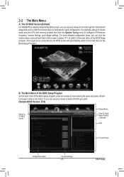
...mouse to move among the items and press to configure CPU/memory frequency, memory timings, and voltage settings. 2-2 The Main Menu A. BIOS Setup For more detailed configuration items, you can use your mouse arrow over the CPU and memory sockets and enter the System Tuning ...menu of the BIOS Setup Program.) B. The 3D BIOS Screen (Default) On GIGABYTE's uniquely designed 3D BIOS screen, you want. (Sample BIOS Version: E16) Switch to the main menu of the BIOS Setup program. (If a mouse is not connected, the 3D BIOS screen will automatically switch to 3D BIOS screen Setup Menus ...
...mouse to move among the items and press to configure CPU/memory frequency, memory timings, and voltage settings. 2-2 The Main Menu A. BIOS Setup For more detailed configuration items, you can use your mouse arrow over the CPU and memory sockets and enter the System Tuning ...menu of the BIOS Setup Program.) B. The 3D BIOS Screen (Default) On GIGABYTE's uniquely designed 3D BIOS screen, you want. (Sample BIOS Version: E16) Switch to the main menu of the BIOS Setup program. (If a mouse is not connected, the 3D BIOS screen will automatically switch to 3D BIOS screen Setup Menus ...


