
Manual
Page 1
... Technology • The Intel Smart Response Technology requires a computer system with an Intel Z68 Chipset-based motherboard and an Intel Core series CPU. • The operating system must be used for your motherboard. If you enable RAID mode. Enabling RAID mode in BIOS Setup 3. Enabling RAID mode in BIOS ...Setup: Turn on the motherboard you also need an SSD to enable the Intel® Smart Response Technology: 1. CMOS Setup Utility-Copyright (C) 1984-2011 Award Software Integrated ...
... Technology • The Intel Smart Response Technology requires a computer system with an Intel Z68 Chipset-based motherboard and an Intel Core series CPU. • The operating system must be used for your motherboard. If you enable RAID mode. Enabling RAID mode in BIOS Setup 3. Enabling RAID mode in BIOS ...Setup: Turn on the motherboard you also need an SSD to enable the Intel® Smart Response Technology: 1. CMOS Setup Utility-Copyright (C) 1984-2011 Award Software Integrated ...

Manual
Page 2
...above and restarting your system, find the IRST icon in the notification area and double-click it to install all motherboard drivers, including the Intel Rapid Storage Technology driver. Make sure the Intel Rapid Storage Technology driver version is complete, use the "...Xpress Install" function of the motherboard driver disk to open the Intel Rapid Storage Technology utility. - 2 - Launching the Intel Rapid Storage Technology utility to install the operating ...
...above and restarting your system, find the IRST icon in the notification area and double-click it to install all motherboard drivers, including the Intel Rapid Storage Technology driver. Make sure the Intel Rapid Storage Technology driver version is complete, use the "...Xpress Install" function of the motherboard driver disk to open the Intel Rapid Storage Technology utility. - 2 - Launching the Intel Rapid Storage Technology utility to install the operating ...
Manual
Page 2
Motherboard GA-Z68XP-UD5 Jun. 3, 2011 Motherboard GA-Z68XP-UD5 Jun. 3, 2011
Motherboard GA-Z68XP-UD5 Jun. 3, 2011 Motherboard GA-Z68XP-UD5 Jun. 3, 2011
Manual
Page 3
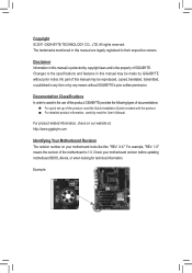
...in this manual may be made by copyright laws and is the property of the motherboard is protected by GIGABYTE without GIGABYTE's prior written permission. For example, "REV: 1.0" means the revision of GIGABYTE. Documentation Classifications In order to their respective owners. Example: Copyright © 2011... of this manual are legally registered to assist in any form or by any means without prior notice. Check your motherboard looks like this product, GIGABYTE provides the following types of documentations: For quick set-up of this : "REV: X.X." All rights reserved...
...in this manual may be made by copyright laws and is the property of the motherboard is protected by GIGABYTE without GIGABYTE's prior written permission. For example, "REV: 1.0" means the revision of GIGABYTE. Documentation Classifications In order to their respective owners. Example: Copyright © 2011... of this manual are legally registered to assist in any form or by any means without prior notice. Check your motherboard looks like this product, GIGABYTE provides the following types of documentations: For quick set-up of this : "REV: X.X." All rights reserved...
Manual
Page 4
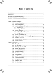
Table of Contents Box Contents...6 Optional Items...6 GA-Z68XP-UD5 Motherboard Layout 7 GA-Z68XP-UD5 Motherboard Block Diagram 8 Chapter 1 Hardware Installation 9 1-1 Installation Precautions 9 1-2 Product Specifications 10 1-3 Installing the CPU and CPU Cooler 13 1-3-1 Installing the CPU 13 1-3-2 Installing the CPU Cooler ...
Table of Contents Box Contents...6 Optional Items...6 GA-Z68XP-UD5 Motherboard Layout 7 GA-Z68XP-UD5 Motherboard Block Diagram 8 Chapter 1 Hardware Installation 9 1-1 Installation Precautions 9 1-2 Product Specifications 10 1-3 Installing the CPU and CPU Cooler 13 1-3-1 Installing the CPU 13 1-3-2 Installing the CPU Cooler ...
Manual
Page 6
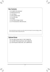
The box contents are for reference only and the actual items shall depend on the product package you obtain. Box Contents GA-Z68XP-UD5 motherboard Motherboard driver disk User's Manual Quick Installation Guide Four SATA cables I/O Shield One 2-Way SLI bridge connector 3.5" Front Panel with 2 USB 3.0/2.0 ports The box contents above are subject to change without notice. Optional Items 2-port USB 2.0 bracket (Part No. 12CR1-1UB030-5*R) 2-port IEEE 1394a bracket (Part No. 12CF1-1IE008-0*R) 2-port SATA power cable (Part No. 12CF1-2SERPW-0*R) - 6 -
The box contents are for reference only and the actual items shall depend on the product package you obtain. Box Contents GA-Z68XP-UD5 motherboard Motherboard driver disk User's Manual Quick Installation Guide Four SATA cables I/O Shield One 2-Way SLI bridge connector 3.5" Front Panel with 2 USB 3.0/2.0 ports The box contents above are subject to change without notice. Optional Items 2-port USB 2.0 bracket (Part No. 12CR1-1UB030-5*R) 2-port IEEE 1394a bracket (Part No. 12CF1-1IE008-0*R) 2-port SATA power cable (Part No. 12CF1-2SERPW-0*R) - 6 -
Manual
Page 7
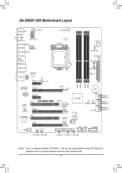
GA-Z68XP-UD5 Motherboard Layout KB_MS_USB SYS_FAN1 R_SPDIF ATX_12V_2X USB_1394_ESATA_1 Marvell 88SE9128 USB_1394_ESATA_2 HDMI R_USB30 CPU_FAN CPU_LED LGA1155 PW_SW PHASE LED PWR_FAN RST_SW USB30_LAN VLI VL810 F_AUDIO AUDIO GD2 PCIEX1_1 (Note) PE1_LED GD1 Realtek RTL8111E PCIEX16 Renesas D720200 PCIEX1_2 PCI1 CODEC GA-Z68XP-UD5 SPDIF_O PCIEX8 T.I. TSB43AB23 PCI2 PCIEX4 F_1394 CMOS_SW DIMM_LED PE_LED DDR3_4 DDR3_2 DDR3_3 DDR3_1 ATX...
GA-Z68XP-UD5 Motherboard Layout KB_MS_USB SYS_FAN1 R_SPDIF ATX_12V_2X USB_1394_ESATA_1 Marvell 88SE9128 USB_1394_ESATA_2 HDMI R_USB30 CPU_FAN CPU_LED LGA1155 PW_SW PHASE LED PWR_FAN RST_SW USB30_LAN VLI VL810 F_AUDIO AUDIO GD2 PCIEX1_1 (Note) PE1_LED GD1 Realtek RTL8111E PCIEX16 Renesas D720200 PCIEX1_2 PCI1 CODEC GA-Z68XP-UD5 SPDIF_O PCIEX8 T.I. TSB43AB23 PCI2 PCIEX4 F_1394 CMOS_SW DIMM_LED PE_LED DDR3_4 DDR3_2 DDR3_3 DDR3_1 ATX...
Manual
Page 8
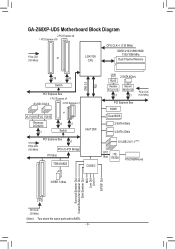
GA-Z68XP-UD5 Motherboard Block Diagram 2 PCI Express x8 1 PCI Express x16 CPU CLK+/- (133 MHz) PCIe CLK or (100 MHz) LGA1155 CPU DDR3 2133/1866/1600/ 1333/1066 ...
GA-Z68XP-UD5 Motherboard Block Diagram 2 PCI Express x8 1 PCI Express x16 CPU CLK+/- (133 MHz) PCIe CLK or (100 MHz) LGA1155 CPU DDR3 2133/1866/1600/ 1333/1066 ...
Manual
Page 9
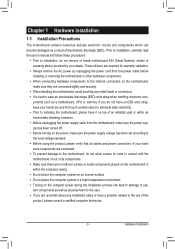
...cables and power connectors of your dealer. Hardware Installation If you are connected tightly and securely. •• When handling the motherboard, avoid touching any installation steps or have it on top of an antistatic pad or within an electrostatic shielding container. •...;• Before unplugging the power supply cable from the power outlet before installing or removing the motherboard or other hardware components. •• When connecting hardware components to the internal connectors on the power, make sure they ...
...cables and power connectors of your dealer. Hardware Installation If you are connected tightly and securely. •• When handling the motherboard, avoid touching any installation steps or have it on top of an antistatic pad or within an electrostatic shielding container. •...;• Before unplugging the power supply cable from the power outlet before installing or removing the motherboard or other hardware components. •• When connecting hardware components to the internal connectors on the power, make sure they ...
Manual
Page 12
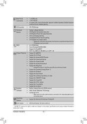
...138;Š Support for Xpress Install ŠŠ Support for Xpress Recovery2 ŠŠ Support for EasyTune * Available functions in EasyTune may differ by motherboard model. ŠŠ Support for Dynamic Energy Saver™ 2 ŠŠ Support for Smart 6™ ŠŠ Support for Auto Green...138;Š Support for Microsoft® Windows 7/Vista/XP Form Factor ŠŠ ATX Form Factor; 30.5cm x 24.4cm * GIGABYTE reserves the right to make any changes to the integrated graphics port on the CPU/system cooler you install. Hardware Installation - 12 -
...138;Š Support for Xpress Install ŠŠ Support for Xpress Recovery2 ŠŠ Support for EasyTune * Available functions in EasyTune may differ by motherboard model. ŠŠ Support for Dynamic Energy Saver™ 2 ŠŠ Support for Smart 6™ ŠŠ Support for Auto Green...138;Š Support for Microsoft® Windows 7/Vista/XP Form Factor ŠŠ ATX Form Factor; 30.5cm x 24.4cm * GIGABYTE reserves the right to make any changes to the integrated graphics port on the CPU/system cooler you install. Hardware Installation - 12 -
Manual
Page 13
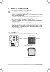
..., memory, hard drive, etc. 1-3-1 Installing the CPU A. It is not installed, otherwise overheating and dam- Locate the alignment keys on the motherboard CPU socket and the notches on the CPU - 13 - Hardware Installation LGA1155 CPU Socket Alignment Key Alignment Key Pin One Corner of the CPU ...;• Apply an even and thin layer of thermal grease on the computer if the CPU cooler is not recommended that the motherboard supports the CPU. (Go to GIGABYTE's website for the peripherals. If you may occur. •• Set the CPU host frequency in accordance with the CPU ...
..., memory, hard drive, etc. 1-3-1 Installing the CPU A. It is not installed, otherwise overheating and dam- Locate the alignment keys on the motherboard CPU socket and the notches on the CPU - 13 - Hardware Installation LGA1155 CPU Socket Alignment Key Alignment Key Pin One Corner of the CPU ...;• Apply an even and thin layer of thermal grease on the computer if the CPU cooler is not recommended that the motherboard supports the CPU. (Go to GIGABYTE's website for the peripherals. If you may occur. •• Set the CPU host frequency in accordance with the CPU ...
Manual
Page 14
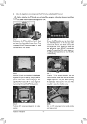
... marking (triangle) with the pin one hand to correctly install the CPU into its locked position. Step 5: Push the CPU socket lever back into the motherboard CPU socket. Step 2: Remove the CPU socket cover as well. Step 4: Once the CPU is not installed.) Step 3: Hold the CPU with your thumb to...
... marking (triangle) with the pin one hand to correctly install the CPU into its locked position. Step 5: Push the CPU socket lever back into the motherboard CPU socket. Step 2: Remove the CPU socket cover as well. Step 4: Once the CPU is not installed.) Step 3: Hold the CPU with your thumb to...
Manual
Page 15
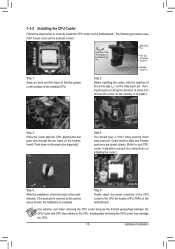
...joined closely. (Refer to your CPU cooler installation manual for instructions on the motherboard. Hardware Installation 1-3-2 Installing the CPU Cooler Follow the steps below to correctly install the CPU cooler on the motherboard. (The following procedure uses Intel® boxed cooler as the picture above ...shows, the installation is complete. Step 4: You should hear a "click" when pushing down on the motherboard. Use extreme care when removing the CPU cooler because the thermal grease/tape between the CPU cooler and CPU may damage the CPU. - ...
...joined closely. (Refer to your CPU cooler installation manual for instructions on the motherboard. Hardware Installation 1-3-2 Installing the CPU Cooler Follow the steps below to correctly install the CPU cooler on the motherboard. (The following procedure uses Intel® boxed cooler as the picture above ...shows, the installation is complete. Step 4: You should hear a "click" when pushing down on the motherboard. Use extreme care when removing the CPU cooler because the thermal grease/tape between the CPU cooler and CPU may damage the CPU. - ...
Manual
Page 16
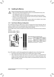
...that you are divided into two channels and each channel has two memory sockets as following guidelines before installing the memory to GIGABYTE's website for the latest supported memory speeds and memory modules.) •• Always turn off the computer and unplug ...Due to insert the memory, switch the direction. 1-4-1 Dual Channel Memory Configuration This motherboard provides four DDR3 memory sockets and supports Dual Channel Technology. After the memory is recommended that the motherboard supports the memory. Hardware Installation - 16 - A memory module can be enabled if...
...that you are divided into two channels and each channel has two memory sockets as following guidelines before installing the memory to GIGABYTE's website for the latest supported memory speeds and memory modules.) •• Always turn off the computer and unplug ...Due to insert the memory, switch the direction. 1-4-1 Dual Channel Memory Configuration This motherboard provides four DDR3 memory sockets and supports Dual Channel Technology. After the memory is recommended that the motherboard supports the memory. Hardware Installation - 16 - A memory module can be enabled if...
Manual
Page 17
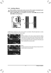
..., make sure to turn off the computer and unplug the power cord from the power outlet to prevent damage to install DDR3 DIMMs on this motherboard. Place the memory module on the top edge of the memory module. Follow the steps below to correctly install your fingers on the socket.
..., make sure to turn off the computer and unplug the power cord from the power outlet to prevent damage to install DDR3 DIMMs on this motherboard. Place the memory module on the top edge of the memory module. Follow the steps below to correctly install your fingers on the socket.
Manual
Page 18
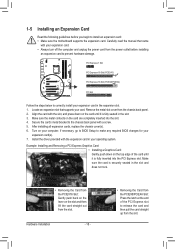
... and does not rock. • Removing the Card from the power outlet before you begin to install an expansion card: •• Make sure the motherboard supports the expansion card. Align the card with your card. Make sure the card is fully seated in the expansion slot. 1. Example: Installing and Removing...
... and does not rock. • Removing the Card from the power outlet before you begin to install an expansion card: •• Make sure the motherboard supports the expansion card. Align the card with your card. Make sure the card is fully seated in the expansion slot. 1. Example: Installing and Removing...
Manual
Page 19
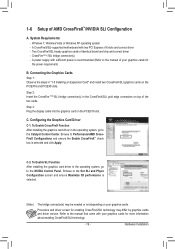
... After installing the graphics card driver in "1-5 Installing an Expansion Card" and install two CrossFireX/SLI graphics cards on the PCIEX16 slot. A CrossFireX/SLI-supported motherboard with your graphics cards for enabling CrossFireX/SLI technology may be needed or not depending on top of identical brand and chip and correct driver...
... After installing the graphics card driver in "1-5 Installing an Expansion Card" and install two CrossFireX/SLI graphics cards on the PCIEX16 slot. A CrossFireX/SLI-supported motherboard with your graphics cards for enabling CrossFireX/SLI technology may be needed or not depending on top of identical brand and chip and correct driver...
Manual
Page 20
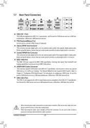
... that supports digital coaxial audio. 1-7 Back Panel Connectors USB 2.0/1.1 Port The USB port supports the USB 2.0/1.1 specification. Do not rock it straight out from the motherboard. •• When removing the cable, pull it side to side to Chapter 5, "Configuring SATA Hard Drive(s)," for USB devices such as a USB keyboard/mouse...
... that supports digital coaxial audio. 1-7 Back Panel Connectors USB 2.0/1.1 Port The USB port supports the USB 2.0/1.1 specification. Do not rock it straight out from the motherboard. •• When removing the cable, pull it side to side to Chapter 5, "Configuring SATA Hard Drive(s)," for USB devices such as a USB keyboard/mouse...
Manual
Page 22
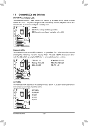
... the yellow LEDs will light up under normal working conditions (green LED) GD2: Excessive overvoltage or overloading (yellow LED) Diagnostic LEDs This motherboard has 6 onboard LEDs controlled by the system BIOS to improper plug/unplug actions. The green LEDs light up during the POST when the .../devices have a problem. CPU VTT: GD1: Normal working conditions; 1-8 Onboard LEDs and Switches CPU VTT Phase Indicator LEDs This motherboard contains 2 phase indicator LEDs controlled by the system BIOS. The LEDs will be illuminated when an excessive overvoltage or overloading occurs.
... the yellow LEDs will light up under normal working conditions (green LED) GD2: Excessive overvoltage or overloading (yellow LED) Diagnostic LEDs This motherboard has 6 onboard LEDs controlled by the system BIOS to improper plug/unplug actions. The green LEDs light up during the POST when the .../devices have a problem. CPU VTT: GD1: Normal working conditions; 1-8 Onboard LEDs and Switches CPU VTT Phase Indicator LEDs This motherboard contains 2 phase indicator LEDs controlled by the system BIOS. The LEDs will be illuminated when an excessive overvoltage or overloading occurs.
Manual
Page 23
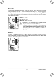
... Energy Saver™ 2," for BIOS configurations). Refer to Chapter 2, "BIOS Setup," for more the number of lighted LEDs indicates the CPU loading. Quick Buttons This motherboard has 3 quick buttons: power button, reset button and clearing CMOS button. Use the clearing CMOS button to factory defaults when needed. Hardware Installation date information...
... Energy Saver™ 2," for BIOS configurations). Refer to Chapter 2, "BIOS Setup," for more the number of lighted LEDs indicates the CPU loading. Quick Buttons This motherboard has 3 quick buttons: power button, reset button and clearing CMOS button. Use the clearing CMOS button to factory defaults when needed. Hardware Installation date information...


