Manual
Page 7
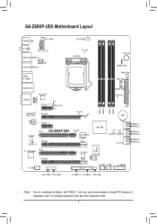
... VLI VL810 F_AUDIO AUDIO GD2 PCIEX1_1 (Note) PE1_LED GD1 Realtek RTL8111E PCIEX16 Renesas D720200 PCIEX1_2 PCI1 CODEC GA-Z68XP-UD5 SPDIF_O PCIEX8 T.I. TSB43AB23 PCI2 PCIEX4 F_1394 CMOS_SW DIMM_LED PE_LED DDR3_4 DDR3_2 DDR3_3 DDR3_1 ATX BAT PCI_LED PCIe to PCI Bridge Intel® Z68 B_BIOS M_BIOS SA_LED iTE IT8728 VLI VL810 S4_S5_LED S3_LED S1_LED S0_LED...
... VLI VL810 F_AUDIO AUDIO GD2 PCIEX1_1 (Note) PE1_LED GD1 Realtek RTL8111E PCIEX16 Renesas D720200 PCIEX1_2 PCI1 CODEC GA-Z68XP-UD5 SPDIF_O PCIEX8 T.I. TSB43AB23 PCI2 PCIEX4 F_1394 CMOS_SW DIMM_LED PE_LED DDR3_4 DDR3_2 DDR3_3 DDR3_1 ATX BAT PCI_LED PCIe to PCI Bridge Intel® Z68 B_BIOS M_BIOS SA_LED iTE IT8728 VLI VL810 S4_S5_LED S3_LED S1_LED S0_LED...
Manual
Page 8
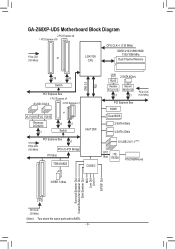
GA-Z68XP-UD5 Motherboard Block Diagram 2 PCI Express x8 1 PCI Express x16 CPU CLK+/- (133 MHz) PCIe CLK or (100 MHz) LGA1155 CPU DDR3 2133/1866/1600/ 1333/...USB 3.0/2.0 3 PCI Express x1 VLI VL810 VLI VL810 Renesas D720200 x1 or x4 x1 Switch PCIe CLK (100 MHz) PCI Express Bus x1 PCIe to PCI Bridge PCI Bus Intel® Z68 TSB43AB23 CODEC DMI 2.0 FDI LAN 2 SATA 6Gb.../s RJ45 Realtek RTL8111E x1 Marvell 88SE9128 x1 PCIe CLK (100 MHz) PCI Express Bus HDMI Dual BIOS 2 SATA 6Gb/s 4 SATA 3Gb/s 10 USB 2.0/1.1 ...
GA-Z68XP-UD5 Motherboard Block Diagram 2 PCI Express x8 1 PCI Express x16 CPU CLK+/- (133 MHz) PCIe CLK or (100 MHz) LGA1155 CPU DDR3 2133/1866/1600/ 1333/...USB 3.0/2.0 3 PCI Express x1 VLI VL810 VLI VL810 Renesas D720200 x1 or x4 x1 Switch PCIe CLK (100 MHz) PCI Express Bus x1 PCIe to PCI Bridge PCI Bus Intel® Z68 TSB43AB23 CODEC DMI 2.0 FDI LAN 2 SATA 6Gb.../s RJ45 Realtek RTL8111E x1 Marvell 88SE9128 x1 PCIe CLK (100 MHz) PCI Express Bus HDMI Dual BIOS 2 SATA 6Gb/s 4 SATA 3Gb/s 10 USB 2.0/1.1 ...
Manual
Page 22
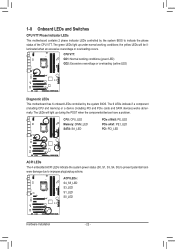
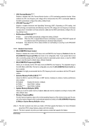
The 6 LEDs indicate if a component (including CPU and memory) or a device (including PCI and PCIe cards and SATA devices) works abnormally. The LEDs will be illuminated when an excessive overvoltage or overloading occurs. the yellow LEDs will light up under ... LED) Diagnostic LEDs This motherboard has 6 onboard LEDs controlled by the system BIOS to improper plug/unplug actions. CPU: CPU_LED Memory: DIMM_LED SATA: SA_LED PCIe x16/x8: PE_LED PCIe x4/x1: PE1_LED PCI: PCI_LED ACPI LEDs The 4 embedded ACPI LEDs indicate the system power status (S0, S1, S3, S4, S5) to prevent...
The 6 LEDs indicate if a component (including CPU and memory) or a device (including PCI and PCIe cards and SATA devices) works abnormally. The LEDs will be illuminated when an excessive overvoltage or overloading occurs. the yellow LEDs will light up under ... LED) Diagnostic LEDs This motherboard has 6 onboard LEDs controlled by the system BIOS to improper plug/unplug actions. CPU: CPU_LED Memory: DIMM_LED SATA: SA_LED PCIe x16/x8: PE_LED PCIe x4/x1: PE1_LED PCI: PCI_LED ACPI LEDs The 4 embedded ACPI LEDs indicate the system power status (S0, S1, S3, S4, S5) to prevent...
Manual
Page 40
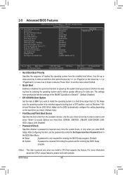
... data. (Default: Auto) Memory Frequency(Mhz) The first memory frequency value is the normal operating frequency of CPU base clock and DMI/PCIe bus frequency. Auto lets the BIOS automatically configure this setting. (Default: Auto) Bi-Directional PROCHOT (Note 1) Auto Lets the BIOS automatically...MHz. Profile2 (Note 2) Uses Profile 2 settings. System Memory Multiplier (SPD) Allows you to manually set the CPU base clock and DMI/PCIe bus frequency. CPU Thermal Monitor (Note 1) Enables or disables Intel CPU Thermal Monitor function, a CPU overheating protection function. Auto lets the...
... data. (Default: Auto) Memory Frequency(Mhz) The first memory frequency value is the normal operating frequency of CPU base clock and DMI/PCIe bus frequency. Auto lets the BIOS automatically configure this setting. (Default: Auto) Bi-Directional PROCHOT (Note 1) Auto Lets the BIOS automatically...MHz. Profile2 (Note 2) Uses Profile 2 settings. System Memory Multiplier (SPD) Allows you to manually set the CPU base clock and DMI/PCIe bus frequency. CPU Thermal Monitor (Note 1) Enables or disables Intel CPU Thermal Monitor function, a CPU overheating protection function. Auto lets the...
Manual
Page 48
... Show Init Display First Onboard VGA On-Chip Frame Buffer Size [Press Enter] [Disabled] [Auto] [Hard Disk] [CDROM] [USB-FDD] [Setup] [Disabled] [Disabled] [Enabled] [0] [Enabled] [PCIE x16] [Auto] [64MB+2MB for entering the BIOS Setup program. (Note) This item is present only when you enter BIOS Setup. to be installed supports...
... Show Init Display First Onboard VGA On-Chip Frame Buffer Size [Press Enter] [Disabled] [Auto] [Hard Disk] [CDROM] [USB-FDD] [Setup] [Disabled] [Disabled] [Enabled] [0] [Enabled] [PCIE x16] [Auto] [64MB+2MB for entering the BIOS Setup program. (Note) This item is present only when you enter BIOS Setup. to be installed supports...
Manual
Page 49
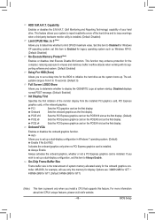
...monitor display from 0 to 15 seconds. (Default: 0) Full Screen LOGO Show Allows you install a CPU that supports this item to display the GIGABYTE Logo at system startup. BIOS Setup HDD S.M.A.R.T. Capability Enables or disables the S.M.A.R.T. (Self Monitoring and Reporting Technology) capability of your system to .... For more information about Intel CPUs' unique features, please visit Intel's website. - 49 - PCIE x16 Sets the PCI Express graphics card on the PCIEX16 slot as the first display. (Default) PCIE x8 Sets the PCI Express graphics card on the PCIEX4 slot as the first display...
...monitor display from 0 to 15 seconds. (Default: 0) Full Screen LOGO Show Allows you install a CPU that supports this item to display the GIGABYTE Logo at system startup. BIOS Setup HDD S.M.A.R.T. Capability Enables or disables the S.M.A.R.T. (Self Monitoring and Reporting Technology) capability of your system to .... For more information about Intel CPUs' unique features, please visit Intel's website. - 49 - PCIE x16 Sets the PCI Express graphics card on the PCIEX16 slot as the first display. (Default) PCIE x8 Sets the PCI Express graphics card on the PCIEX4 slot as the first display...
Manual
Page 53
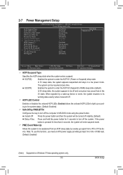
... Management Setup ACPI Suspend Type ACPI LED Control Soft-Off by PWR-BTTN PME Event Wake Up Resume by a wake-up signal from a PCI or PCIe device. PME Event Wake Up Allows the system to its working state exactly where it was left off and consumes less power than 4 seconds, the...
... Management Setup ACPI Suspend Type ACPI LED Control Soft-Off by PWR-BTTN PME Event Wake Up Resume by a wake-up signal from a PCI or PCIe device. PME Event Wake Up Allows the system to its working state exactly where it was left off and consumes less power than 4 seconds, the...
Manual
Page 82
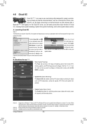
... XP, be able to view your dedicated IP and you can easily access three major functions of tweaking options that include CPU, memory, graphics, and PCIe frequencies and voltages. Available functions may differ by motherboard model. A. Click the or but- Launching Cloud OC Step 1: The first time you launch Cloud OC...
... XP, be able to view your dedicated IP and you can easily access three major functions of tweaking options that include CPU, memory, graphics, and PCIe frequencies and voltages. Available functions may differ by motherboard model. A. Click the or but- Launching Cloud OC Step 1: The first time you launch Cloud OC...

Manual
Page 94
... 0 : Marvell 0 Virtual Disks Free Physical Disks HDD 0: WDC WD800JD-22L HDD 1: WDC WD800JD-22L Information Vendor ID : Device ID : Revision ID : BIOS Version : Firmware Version : PCIe Speed rate : Configure SATA as : Supported Mode : 1B4B 91A3 B1 1.0.0.1029 2.2.0.1113 5.0Gbps IDE Mode RAID 0 RAID 1 Help Marvell RAID on chip controller. Marvell BIOS...
... 0 : Marvell 0 Virtual Disks Free Physical Disks HDD 0: WDC WD800JD-22L HDD 1: WDC WD800JD-22L Information Vendor ID : Device ID : Revision ID : BIOS Version : Firmware Version : PCIe Speed rate : Configure SATA as : Supported Mode : 1B4B 91A3 B1 1.0.0.1029 2.2.0.1113 5.0Gbps IDE Mode RAID 0 RAID 1 Help Marvell RAID on chip controller. Marvell BIOS...
Manual
Page 96
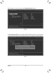
... WD800JD-22L HDD 1 : WDC WD800JD-22L Free Physical Disks Information Vendor ID : Device ID : Revision ID : BIOS Version : Firmware Version : PCIe Speed rate : Configure SATA as : Supported Mode : Do you can see the new array under Topology\Virtual Disks (Figure 6). Press to confirm or... 0: WDC WD800JD-22L HDD 1: WDC WD800JD-22L Free Physical Disks Exit Vendor ID : Device ID : Revision ID : BIOS Version : Firmware Version : PCIe Speed rate : Configure SATA as : Supported Mode : 1B4B 91A3 B1 1.0.0.1029 2.2.0.1113 5.0Gbps IDE Mode RAID 0 RAID 1 Help Marvell RAID on chip...
... WD800JD-22L HDD 1 : WDC WD800JD-22L Free Physical Disks Information Vendor ID : Device ID : Revision ID : BIOS Version : Firmware Version : PCIe Speed rate : Configure SATA as : Supported Mode : Do you can see the new array under Topology\Virtual Disks (Figure 6). Press to confirm or... 0: WDC WD800JD-22L HDD 1: WDC WD800JD-22L Free Physical Disks Exit Vendor ID : Device ID : Revision ID : BIOS Version : Firmware Version : PCIe Speed rate : Configure SATA as : Supported Mode : 1B4B 91A3 B1 1.0.0.1029 2.2.0.1113 5.0Gbps IDE Mode RAID 0 RAID 1 Help Marvell RAID on chip...
Manual
Page 97
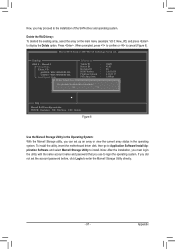
... New_VD HDD 0: WDC WD800JD-22L HDD 1: WDC WD800JD-22L Free Physical Disks Delete Virtual Disk Vendor ID : Device ID : Revision ID : BIOS Version : Firmware Version : PCIe Speed rate : Configure SATA as : Supported Mode : Do you want to display the Delete option. Note: After the installation, you must login the utility with...
... New_VD HDD 0: WDC WD800JD-22L HDD 1: WDC WD800JD-22L Free Physical Disks Delete Virtual Disk Vendor ID : Device ID : Revision ID : BIOS Version : Firmware Version : PCIe Speed rate : Configure SATA as : Supported Mode : Do you want to display the Delete option. Note: After the installation, you must login the utility with...


