
Manual
Page 1
... Storage Technology utility to enable the Intel Smart Response Technology • The Intel Smart Response Technology requires a computer system with an Intel Z68 Chipset-based motherboard and an Intel Core series CPU. • The operating system must be installed to the SATA disk. • Supported operating systems include Windows 7 ... If you have and the BIOS version. - 1 - Enabling RAID mode in BIOS Setup: Turn on the hard disk will see shall depend on the motherboard you back up the hard disk before configuring the Smart Response Technology, all original data on your...
... Storage Technology utility to enable the Intel Smart Response Technology • The Intel Smart Response Technology requires a computer system with an Intel Z68 Chipset-based motherboard and an Intel Core series CPU. • The operating system must be installed to the SATA disk. • Supported operating systems include Windows 7 ... If you have and the BIOS version. - 1 - Enabling RAID mode in BIOS Setup: Turn on the hard disk will see shall depend on the motherboard you back up the hard disk before configuring the Smart Response Technology, all original data on your...

Manual
Page 2
Installing the operating system and drivers to the SATA disk: After setting the BIOS, you can begin to install all motherboard drivers, including the Intel Rapid Storage Technology driver. After the installation is 10.5 or above and restarting your system, fi... completing the steps above . 4. Make sure the Intel Rapid Storage Technology driver version is complete, use the "Xpress Install" function of the motherboard driver disk to install the operating system. Launching the Intel Rapid Storage Technology utility to open the Intel Rapid Storage Technology utility. - 2 - English 3....
Installing the operating system and drivers to the SATA disk: After setting the BIOS, you can begin to install all motherboard drivers, including the Intel Rapid Storage Technology driver. After the installation is 10.5 or above and restarting your system, fi... completing the steps above . 4. Make sure the Intel Rapid Storage Technology driver version is complete, use the "Xpress Install" function of the motherboard driver disk to install the operating system. Launching the Intel Rapid Storage Technology utility to open the Intel Rapid Storage Technology utility. - 2 - English 3....
Manual
Page 3
... check on our website at: http://www.gigabyte.com Identifying Your Motherboard Revision The revision number on your motherboard revision before updating motherboard BIOS, drivers, or when looking for technical information. Example: No part of GIGABYTE. Documentation Classifications In order to their respective..., "REV: 1.0" means the revision of the motherboard is the property of this manual may be reproduced, copied, translated, transmitted, or published in this manual may be made by GIGABYTE without GIGABYTE's prior written permission. The trademarks mentioned in this...
... check on our website at: http://www.gigabyte.com Identifying Your Motherboard Revision The revision number on your motherboard revision before updating motherboard BIOS, drivers, or when looking for technical information. Example: No part of GIGABYTE. Documentation Classifications In order to their respective..., "REV: 1.0" means the revision of the motherboard is the property of this manual may be reproduced, copied, translated, transmitted, or published in this manual may be made by GIGABYTE without GIGABYTE's prior written permission. The trademarks mentioned in this...
Manual
Page 4
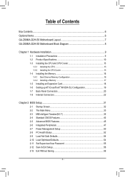
Table of Contents Box Contents...6 Optional Items...6 GA-Z68MA-D2H-B3 Motherboard Layout 7 GA-Z68MA-D2H-B3 Motherboard Block Diagram 8 Chapter 1 Hardware Installation 9 1-1 Installation Precautions 9 1-2 Product Specifications 10 1-3 Installing the CPU and CPU Cooler 13 1-3-1 Installing the CPU 13 1-3-2 Installing the CPU Cooler ...
Table of Contents Box Contents...6 Optional Items...6 GA-Z68MA-D2H-B3 Motherboard Layout 7 GA-Z68MA-D2H-B3 Motherboard Block Diagram 8 Chapter 1 Hardware Installation 9 1-1 Installation Precautions 9 1-2 Product Specifications 10 1-3 Installing the CPU and CPU Cooler 13 1-3-1 Installing the CPU 13 1-3-2 Installing the CPU Cooler ...
Manual
Page 6
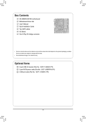
The box contents are for reference only. Optional Items 2-port USB 2.0 bracket (Part No. 12CR1-1UB030-5*R) 2-port SATA power cable (Part No. 12CF1-2SERPW-0*R) COM port cable (Part No. 12CF1-1CM001-3*R) - 6 - Box Contents GA-Z68MA-D2H-B3 motherboard Motherboard driver disk User's Manual Quick Installation Guide Two SATA cables I/O Shield One 2-Way SLI bridge connector • The box contents above are subject to change without notice. • The motherboard image is for reference only and the actual items shall depend on the product package you obtain.
The box contents are for reference only. Optional Items 2-port USB 2.0 bracket (Part No. 12CR1-1UB030-5*R) 2-port SATA power cable (Part No. 12CF1-2SERPW-0*R) COM port cable (Part No. 12CF1-1CM001-3*R) - 6 - Box Contents GA-Z68MA-D2H-B3 motherboard Motherboard driver disk User's Manual Quick Installation Guide Two SATA cables I/O Shield One 2-Way SLI bridge connector • The box contents above are subject to change without notice. • The motherboard image is for reference only and the actual items shall depend on the product package you obtain.
Manual
Page 7
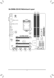
GA-Z68MA-D2H-B3 Motherboard Layout DDR3_4 DDR3_2 DDR3_3 DDR3_1 KB_USB ATX_12V VGA_DVI LEVEL SHIFTER LGA1155 HDMI LEVEL SHIFTER OPTICAL USB30_20 USB_LAN Etron EJ168 CPU_FAN AUDIO PCIEX16 GA-Z68MA-D2H-B3 Realtek RTL8111E PCIEX1 BAT PCIEX4 CODEC PCIEX8 SPDIF_O F_AUDIO F_USB4 F_USB3 F_USB2 F_USB1 ATX SYS_FAN TPM iTE IT8728 B_BIOS M_BIOS Intel® Z68 SATA3_0 SATA3_1 SATA2_2 SATA2_3 SATA2_4 SATA2_5 CLR_CMOS COM F_PANEL - 7 -
GA-Z68MA-D2H-B3 Motherboard Layout DDR3_4 DDR3_2 DDR3_3 DDR3_1 KB_USB ATX_12V VGA_DVI LEVEL SHIFTER LGA1155 HDMI LEVEL SHIFTER OPTICAL USB30_20 USB_LAN Etron EJ168 CPU_FAN AUDIO PCIEX16 GA-Z68MA-D2H-B3 Realtek RTL8111E PCIEX1 BAT PCIEX4 CODEC PCIEX8 SPDIF_O F_AUDIO F_USB4 F_USB3 F_USB2 F_USB1 ATX SYS_FAN TPM iTE IT8728 B_BIOS M_BIOS Intel® Z68 SATA3_0 SATA3_1 SATA2_2 SATA2_3 SATA2_4 SATA2_5 CLR_CMOS COM F_PANEL - 7 -
Manual
Page 8
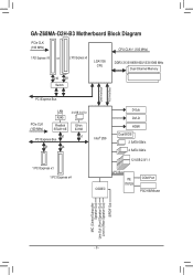
GA-Z68MA-D2H-B3 Motherboard Block Diagram PCIe CLK (100 MHz) CPU CLK+/- (100 MHz) 1 PCI Express x16 or 2 PCI Express x8 LGA1155 CPU DDR3 2133/1866/1600/1333/1066 ...
GA-Z68MA-D2H-B3 Motherboard Block Diagram PCIe CLK (100 MHz) CPU CLK+/- (100 MHz) 1 PCI Express x16 or 2 PCI Express x8 LGA1155 CPU DDR3 2133/1866/1600/1333/1066 ...
Manual
Page 9
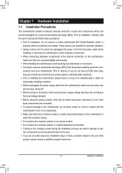
...on an uneven surface. •• Do not place the computer system in a high-temperature environment. •• Turning on the motherboard, make sure the power supply voltage has been set according to the local voltage standard. •• Before using the product, please ...(ESD) wrist strap when handling electronic com- These stickers are connected tightly and securely. •• When handling the motherboard, avoid touching any installation steps or have a problem related to the use of electrostatic discharge (ESD). Chapter 1 Hardware Installation 1-1 Installation Precautions ...
...on an uneven surface. •• Do not place the computer system in a high-temperature environment. •• Turning on the motherboard, make sure the power supply voltage has been set according to the local voltage standard. •• Before using the product, please ...(ESD) wrist strap when handling electronic com- These stickers are connected tightly and securely. •• When handling the motherboard, avoid touching any installation steps or have a problem related to the use of electrostatic discharge (ESD). Chapter 1 Hardware Installation 1-1 Installation Precautions ...
Manual
Page 12
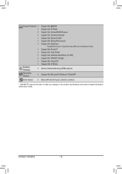
...ŠŠ Support for Xpress Install ŠŠ Support for Xpress Recovery2 ŠŠ Support for EasyTune * Available functions in EasyTune may differ by motherboard model. ŠŠ Support for Smart 6™ ŠŠ Support for Auto Green ŠŠ Support for eXtreme Hard Drive (X.H.D) ŠŠ... ŠŠ Support for Microsoft® Windows 7/Vista/XP Form Factor ŠŠ Micro ATX Form Factor; 24.4cm x 24.4cm * GIGABYTE reserves the right to make any changes to the product specifications and product-related information without prior notice.
...ŠŠ Support for Xpress Install ŠŠ Support for Xpress Recovery2 ŠŠ Support for EasyTune * Available functions in EasyTune may differ by motherboard model. ŠŠ Support for Smart 6™ ŠŠ Support for Auto Green ŠŠ Support for eXtreme Hard Drive (X.H.D) ŠŠ... ŠŠ Support for Microsoft® Windows 7/Vista/XP Form Factor ŠŠ Micro ATX Form Factor; 24.4cm x 24.4cm * GIGABYTE reserves the right to make any changes to the product specifications and product-related information without prior notice.

Manual
Page 13
... computer and unplug the power cord from the power outlet before you begin to install the CPU: •• Make sure that the motherboard supports the CPU. (Go to GIGABYTE's website for the latest CPU support list.) •• Always turn on the computer if the CPU cooler is not recommended that...
... computer and unplug the power cord from the power outlet before you begin to install the CPU: •• Make sure that the motherboard supports the CPU. (Go to GIGABYTE's website for the latest CPU support list.) •• Always turn on the computer if the CPU cooler is not recommended that...

Manual
Page 14
... may align the CPU notches with the pin one hand to lightly replace the load plate. Step 5: Push the CPU socket lever back into the motherboard CPU socket.
... may align the CPU notches with the pin one hand to lightly replace the load plate. Step 5: Push the CPU socket lever back into the motherboard CPU socket.

Manual
Page 15
1-3-2 Installing the CPU Cooler Follow the steps below to correctly install the CPU cooler on the motherboard. (The following procedure uses Intel® boxed cooler as the picture above shows, the installation is complete. Push down each push pin. Check that the ... Pin The Top of Female Push Pin Female Push Pin Step 1: Apply an even and thin layer of thermal grease on the surface of the motherboard. Hardware Installation Use extreme care when removing the CPU cooler because the thermal grease/tape between the CPU cooler and CPU may damage the CPU...
1-3-2 Installing the CPU Cooler Follow the steps below to correctly install the CPU cooler on the motherboard. (The following procedure uses Intel® boxed cooler as the picture above shows, the installation is complete. Push down each push pin. Check that the ... Pin The Top of Female Push Pin Female Push Pin Step 1: Apply an even and thin layer of thermal grease on the surface of the motherboard. Hardware Installation Use extreme care when removing the CPU cooler because the thermal grease/tape between the CPU cooler and CPU may damage the CPU...

Manual
Page 16
...to install the memory: •• Make sure that memory of the same capacity, brand, speed, and chips be used . (Go to GIGABYTE's website for optimum performance. 1-4 Installing the Memory Read the following guidelines before you begin to insert the memory, switch the direction. 1-4-1 Dual... Channel Memory Configuration This motherboard provides four DDR3 memory sockets and supports Dual Channel Technology. DS/SS DS/SS DDR3_2 DS/SS - DS/SS DS/SS DDR3_1 DS/...
...to install the memory: •• Make sure that memory of the same capacity, brand, speed, and chips be used . (Go to GIGABYTE's website for optimum performance. 1-4 Installing the Memory Read the following guidelines before you begin to insert the memory, switch the direction. 1-4-1 Dual... Channel Memory Configuration This motherboard provides four DDR3 memory sockets and supports Dual Channel Technology. DS/SS DS/SS DDR3_2 DS/SS - DS/SS DS/SS DDR3_1 DS/...

Manual
Page 17
..., make sure to turn off the computer and unplug the power cord from the power outlet to prevent damage to install DDR3 DIMMs on this motherboard. As indicated in the picture on the socket. DDR3 and DDR2 DIMMs are not compatible to each other or DDR DIMMs. Be sure to the...
..., make sure to turn off the computer and unplug the power cord from the power outlet to prevent damage to install DDR3 DIMMs on this motherboard. As indicated in the picture on the socket. DDR3 and DDR2 DIMMs are not compatible to each other or DDR DIMMs. Be sure to the...
Manual
Page 18
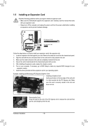
... cards, replace the chassis cover(s). 666 Turn on the top edge of the PCI Express slot to install an expansion card: • Make sure the motherboard supports the expansion card. If necessary, go to BIOS Setup to make any required BIOS changes for your expansion card(s). 777 Install the driver provided...
... cards, replace the chassis cover(s). 666 Turn on the top edge of the PCI Express slot to install an expansion card: • Make sure the motherboard supports the expansion card. If necessary, go to BIOS Setup to make any required BIOS changes for your expansion card(s). 777 Install the driver provided...
Manual
Page 19
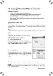
... in the operating system, go to the manual of identical brand and chip and correct driver - Browse to the NVIDIA Control Panel. A CrossFireX/SLI-supported motherboard with your graphics cards. C. Configuring the Graphics Card Driver C-1. Connecting the Graphics Cards Step 1: Observe the steps in "1-5 Installing an Expansion Card" and install two...
... in the operating system, go to the manual of identical brand and chip and correct driver - Browse to the NVIDIA Control Panel. A CrossFireX/SLI-supported motherboard with your graphics cards. C. Configuring the Graphics Card Driver C-1. Connecting the Graphics Cards Step 1: Observe the steps in "1-5 Installing an Expansion Card" and install two...
Manual
Page 21
... in jack. This jack can be connected to 1 Gbps data rate. Hardware Installation Before using this audio jack for the Onboard Graphics: This motherboard provides three video output ports: D-Sub, DVI-D, and HDMI. Optical S/PDIF Out Connector This connector provides digital audio out to an external audio...8226;• When removing the cable connected to a back panel connector, first remove the cable from your device and then remove it from the motherboard. •• When removing the cable, pull it side to side to use an HD front panel audio module and enable the multi-...
... in jack. This jack can be connected to 1 Gbps data rate. Hardware Installation Before using this audio jack for the Onboard Graphics: This motherboard provides three video output ports: D-Sub, DVI-D, and HDMI. Optical S/PDIF Out Connector This connector provides digital audio out to an external audio...8226;• When removing the cable connected to a back panel connector, first remove the cable from your device and then remove it from the motherboard. •• When removing the cable, pull it side to side to use an HD front panel audio module and enable the multi-...

Manual
Page 22
... sure your devices are compliant with the connectors you wish to connect. •• Before installing the devices, be sure to the connector on the motherboard. Unplug the power cord from the power outlet to prevent damage to the devices. •• After installing the device and before connecting external devices...
... sure your devices are compliant with the connectors you wish to connect. •• Before installing the devices, be sure to the connector on the motherboard. Unplug the power cord from the power outlet to prevent damage to the devices. •• After installing the device and before connecting external devices...

Manual
Page 23
... can supply enough stable power to all devices are properly installed. If the 12V power connector is turned off and all the components on the motherboard. To meet expansion requirements, it is used that can withstand high power consumption be used (500W or greater). Hardware Installation 1/2) ATX_12V/ATX (2x2 12V Power...
... can supply enough stable power to all devices are properly installed. If the 12V power connector is turned off and all the components on the motherboard. To meet expansion requirements, it is used that can withstand high power consumption be used (500W or greater). Hardware Installation 1/2) ATX_12V/ATX (2x2 12V Power...

Manual
Page 24
... must be sure to touch the positive and negative terminals of a CPU fan with local environmental regulations. Most fan headers possess a foolproof insertion design. The motherboard supports CPU fan speed control, which requires the use a metal object like a screwdriver to connect it is replaced with an equivalent one minute. (Or use... chassis. 1 CPU_FAN CPU_FAN: Pin No. For optimum heat dissipation, it in the CMOS when the computer is the ground wire). 3/4) CPU_FAN/SYS_FAN (Fan Headers) The motherboard has a 4-pin CPU fan header (CPU_FAN), a 4-pin system fan header (SYS_FAN).
... must be sure to touch the positive and negative terminals of a CPU fan with local environmental regulations. Most fan headers possess a foolproof insertion design. The motherboard supports CPU fan speed control, which requires the use a metal object like a screwdriver to connect it is replaced with an equivalent one minute. (Or use... chassis. 1 CPU_FAN CPU_FAN: Pin No. For optimum heat dissipation, it in the CMOS when the computer is the ground wire). 3/4) CPU_FAN/SYS_FAN (Fan Headers) The motherboard has a 4-pin CPU fan header (CPU_FAN), a 4-pin system fan header (SYS_FAN).


