
Manual
Page 1
...up the hard disk before configuring the Smart Response Technology, all original data on the hard disk will see shall depend on your motherboard. Enabling RAID mode in BIOS Setup 3. Then save changes and exit BIOS Setup. Installing a conventional SATA hard disk and a solid-state drive... utility to enable the Intel Smart Response Technology • The Intel Smart Response Technology requires a computer system with an Intel Z68 Chipset-based motherboard and an Intel Core series CPU. • The operating system must be installed to make it work as a cache of the hard disk...
...up the hard disk before configuring the Smart Response Technology, all original data on the hard disk will see shall depend on your motherboard. Enabling RAID mode in BIOS Setup 3. Then save changes and exit BIOS Setup. Installing a conventional SATA hard disk and a solid-state drive... utility to enable the Intel Smart Response Technology • The Intel Smart Response Technology requires a computer system with an Intel Z68 Chipset-based motherboard and an Intel Core series CPU. • The operating system must be installed to make it work as a cache of the hard disk...

Manual
Page 2
...-click it to install the operating system. Make sure the Intel Rapid Storage Technology driver version is complete, use the "Xpress Install" function of the motherboard driver disk to install all motherboard drivers, including the Intel Rapid Storage Technology driver.
...-click it to install the operating system. Make sure the Intel Rapid Storage Technology driver version is complete, use the "Xpress Install" function of the motherboard driver disk to install all motherboard drivers, including the Intel Rapid Storage Technology driver.
Manual
Page 3
... : "REV: X.X." For product-related information, check on our website at: http://www.gigabyte.com Identifying Your Motherboard Revision The revision number on your motherboard revision before updating motherboard BIOS, drivers, or when looking for technical information. Check your motherboard looks like this product, GIGABYTE provides the following types of documentations: For quick set-up of...
... : "REV: X.X." For product-related information, check on our website at: http://www.gigabyte.com Identifying Your Motherboard Revision The revision number on your motherboard revision before updating motherboard BIOS, drivers, or when looking for technical information. Check your motherboard looks like this product, GIGABYTE provides the following types of documentations: For quick set-up of...
Manual
Page 4
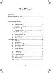
Table of Contents Box Contents...6 Optional Items...6 GA-Z68AP-D3 Motherboard Layout 7 GA-Z68AP-D3 Motherboard Block Diagram 8 Chapter 1 Hardware Installation 9 1-1 Installation Precautions 9 1-2 Product Specifications 10 1-3 Installing the CPU and CPU Cooler 13 1-3-1 Installing the CPU 13 1-3-2 Installing the CPU Cooler ...
Table of Contents Box Contents...6 Optional Items...6 GA-Z68AP-D3 Motherboard Layout 7 GA-Z68AP-D3 Motherboard Block Diagram 8 Chapter 1 Hardware Installation 9 1-1 Installation Precautions 9 1-2 Product Specifications 10 1-3 Installing the CPU and CPU Cooler 13 1-3-1 Installing the CPU 13 1-3-2 Installing the CPU Cooler ...
Manual
Page 6
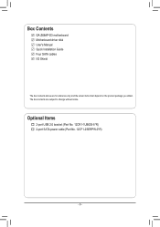
The box contents are for reference only and the actual items shall depend on the product package you obtain. Box Contents GA-Z68AP-D3 motherboard Motherboard driver disk User's Manual Quick Installation Guide Four SATA cables I/O Shield The box contents above are subject to change without notice. Optional Items 2-port USB 2.0 bracket (Part No. 12CR1-1UB030-5*R) 2-port SATA power cable (Part No. 12CF1-2SERPW-0*R) - 6 -
The box contents are for reference only and the actual items shall depend on the product package you obtain. Box Contents GA-Z68AP-D3 motherboard Motherboard driver disk User's Manual Quick Installation Guide Four SATA cables I/O Shield The box contents above are subject to change without notice. Optional Items 2-port USB 2.0 bracket (Part No. 12CR1-1UB030-5*R) 2-port SATA power cable (Part No. 12CF1-2SERPW-0*R) - 6 -
Manual
Page 7
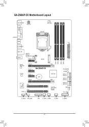
GA-Z68AP-D3 Motherboard Layout KB_MS_USB ATX_12V CPU_FAN COMA LPT LGA1155 OPTICAL HDMI R_USB30/20 USB_LAN AUDIO Etron EJ168 SYS_FAN1 PCIEX1_1 mSATA Realtek RTL8111E CODEC PCIEX16 PCIEX1_2 GA-Z68AP-D3 PCIEX1_3 BAT PCIEX4 PCI1 iTE IT8728 PCI2 SPDIF_O Intel® Z68 PCIe to PCI Bridge DDR3_4 DDR3_2 DDR3_3 DDR3_1 ATX M_BIOS B_BIOS SATA3_1 SATA3_0 SATA2_3 SATA2_2 SATA2_5 SATA2_4 PWR_FAN CLR_CMOS F_AUDIO SYS_FAN2 TPM F_USB3 F_USB2 F_USB1 F_PANEL - 7 -
GA-Z68AP-D3 Motherboard Layout KB_MS_USB ATX_12V CPU_FAN COMA LPT LGA1155 OPTICAL HDMI R_USB30/20 USB_LAN AUDIO Etron EJ168 SYS_FAN1 PCIEX1_1 mSATA Realtek RTL8111E CODEC PCIEX16 PCIEX1_2 GA-Z68AP-D3 PCIEX1_3 BAT PCIEX4 PCI1 iTE IT8728 PCI2 SPDIF_O Intel® Z68 PCIe to PCI Bridge DDR3_4 DDR3_2 DDR3_3 DDR3_1 ATX M_BIOS B_BIOS SATA3_1 SATA3_0 SATA2_3 SATA2_2 SATA2_5 SATA2_4 PWR_FAN CLR_CMOS F_AUDIO SYS_FAN2 TPM F_USB3 F_USB2 F_USB1 F_PANEL - 7 -
Manual
Page 8
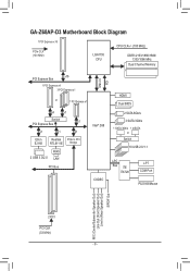
GA-Z68AP-D3 Motherboard Block Diagram 1 PCI Express x16 PCIe CLK (100 MHz) LGA1155 CPU CPU CLK+/- (100 MHz) DDR3 2133/1866/1600/ 1333/1066 MHz Dual Channel Memory ...
GA-Z68AP-D3 Motherboard Block Diagram 1 PCI Express x16 PCIe CLK (100 MHz) LGA1155 CPU CPU CLK+/- (100 MHz) DDR3 2133/1866/1600/ 1333/1066 MHz Dual Channel Memory ...
Manual
Page 9
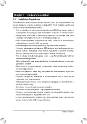
...off. •• Before turning on the power, make sure they are connected tightly and securely. •• When handling the motherboard, avoid touching any installation steps or have a problem related to the internal connectors on the computer power during the installation process can ...: •• Prior to installation, do not allow screws to come in a high-temperature environment. •• Turning on the motherboard, make sure the power supply voltage has been set according to the local voltage standard. •• Before using the product, please verify...
...off. •• Before turning on the power, make sure they are connected tightly and securely. •• When handling the motherboard, avoid touching any installation steps or have a problem related to the internal connectors on the computer power during the installation process can ...: •• Prior to installation, do not allow screws to come in a high-temperature environment. •• Turning on the motherboard, make sure the power supply voltage has been set according to the local voltage standard. •• Before using the product, please verify...
Manual
Page 12
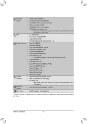
...138; Support for Xpress Install ŠŠ Support for Xpress Recovery2 ŠŠ Support for EasyTune * Available functions in EasyTune may differ by motherboard model. ŠŠ Support for Smart 6™ ŠŠ Support for Auto Green ŠŠ Support for eXtreme Hard Drive (X.H.D) &#...138;Š Support for Microsoft® Windows 7/Vista/XP Form Factor ŠŠ ATX Form Factor; 30.5cm x 21.5cm * GIGABYTE reserves the right to make any changes to the integrated graphics port on the CPU/system cooler you install. Hardware ŠŠ System voltage...
...138; Support for Xpress Install ŠŠ Support for Xpress Recovery2 ŠŠ Support for EasyTune * Available functions in EasyTune may differ by motherboard model. ŠŠ Support for Smart 6™ ŠŠ Support for Auto Green ŠŠ Support for eXtreme Hard Drive (X.H.D) &#...138;Š Support for Microsoft® Windows 7/Vista/XP Form Factor ŠŠ ATX Form Factor; 30.5cm x 21.5cm * GIGABYTE reserves the right to make any changes to the integrated graphics port on the CPU/system cooler you install. Hardware ŠŠ System voltage...
Manual
Page 13
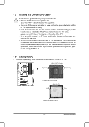
If you may occur. •• Set the CPU host frequency in accordance with the CPU specifications. Locate the alignment keys on the motherboard CPU socket and the notches on the CPU - 13 - age of the CPU may locate the notches on both sides of the CPU and alignment ... do so according to your hardware specifications including the CPU, graphics card, memory, hard drive, etc. 1-3-1 Installing the CPU A. It is not recommended that the motherboard supports the CPU. (Go to GIGABYTE's website for the peripherals. Hardware Installation
If you may occur. •• Set the CPU host frequency in accordance with the CPU specifications. Locate the alignment keys on the motherboard CPU socket and the notches on the CPU - 13 - age of the CPU may locate the notches on both sides of the CPU and alignment ... do so according to your hardware specifications including the CPU, graphics card, memory, hard drive, etc. 1-3-1 Installing the CPU A. It is not recommended that the motherboard supports the CPU. (Go to GIGABYTE's website for the peripherals. Hardware Installation
Manual
Page 14
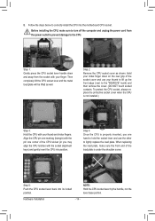
....) Step 3: Hold the CPU with the socket alignment keys) and gently insert the CPU into position. Step 5: Push the CPU socket lever back into the motherboard CPU socket. Hardware Installation - 14 - Step 4: Once the CPU is under the shoulder screw. Follow the steps below to the "REMOVE" mark) and then remove...
....) Step 3: Hold the CPU with the socket alignment keys) and gently insert the CPU into position. Step 5: Push the CPU socket lever back into the motherboard CPU socket. Hardware Installation - 14 - Step 4: Once the CPU is under the shoulder screw. Follow the steps below to the "REMOVE" mark) and then remove...

Manual
Page 15
... an even and thin layer of thermal grease on the surface of the installed CPU. Step 6: Finally, attach the power connector of the motherboard. Push down each push pin. Inadequately removing the CPU cooler may adhere to the CPU. Use extreme care when removing the CPU cooler because... and CPU may damage the CPU. - 15 - 1-3-2 Installing the CPU Cooler Follow the steps below to correctly install the CPU cooler on the motherboard. (The following procedure uses Intel® boxed cooler as the picture above shows, the installation is complete. Step 2: Before installing the cooler, note...
... an even and thin layer of thermal grease on the surface of the installed CPU. Step 6: Finally, attach the power connector of the motherboard. Push down each push pin. Inadequately removing the CPU cooler may adhere to the CPU. Use extreme care when removing the CPU cooler because... and CPU may damage the CPU. - 15 - 1-3-2 Installing the CPU Cooler Follow the steps below to correctly install the CPU cooler on the motherboard. (The following procedure uses Intel® boxed cooler as the picture above shows, the installation is complete. Step 2: Before installing the cooler, note...
Manual
Page 16
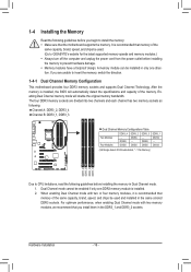
... Four Modules DDR3_4 - The four DDR3 memory sockets are unable to insert the memory, switch the direction. 1-4-1 Dual Channel Memory Configuration This motherboard provides four DDR3 memory sockets and supports Dual Channel Technology. Hardware Installation - 16 - A memory module can be installed in Dual Channel mode...install the memory: •• Make sure that memory of the same capacity, brand, speed, and chips be used . (Go to GIGABYTE's website for the latest supported memory speeds and memory modules.) •• Always turn off the computer and unplug the power cord from...
... Four Modules DDR3_4 - The four DDR3 memory sockets are unable to insert the memory, switch the direction. 1-4-1 Dual Channel Memory Configuration This motherboard provides four DDR3 memory sockets and supports Dual Channel Technology. Hardware Installation - 16 - A memory module can be installed in Dual Channel mode...install the memory: •• Make sure that memory of the same capacity, brand, speed, and chips be used . (Go to GIGABYTE's website for the latest supported memory speeds and memory modules.) •• Always turn off the computer and unplug the power cord from...

Manual
Page 17
.... Follow the steps below to the memory module. Spread the retaining clips at both ends of the memory socket. Place the memory module on this motherboard. As indicated in the picture on the left, place your memory modules in one direction. 1-4-2 Installing a Memory Before installing a memory module, make sure to turn...
.... Follow the steps below to the memory module. Spread the retaining clips at both ends of the memory socket. Place the memory module on this motherboard. As indicated in the picture on the left, place your memory modules in one direction. 1-4-2 Installing a Memory Before installing a memory module, make sure to turn...
Manual
Page 18
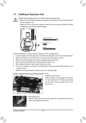
... slot. Hardware Installation - 18 - Remove the metal slot cover from the power outlet before you begin to install an expansion card: • Make sure the motherboard supports the expansion card. PCI Express x16 Slot PCI Express x1 Slot PCI Slot Follow the steps below to correctly install your expansion card in...
... slot. Hardware Installation - 18 - Remove the metal slot cover from the power outlet before you begin to install an expansion card: • Make sure the motherboard supports the expansion card. PCI Express x16 Slot PCI Express x1 Slot PCI Slot Follow the steps below to correctly install your expansion card in...
Manual
Page 19
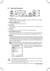
... Out Connector This connector provides digital audio out to a back panel connector, first remove the cable from your device and then remove it from the motherboard. •• When removing the cable, pull it side to side to connect devices such as a USB keyboard/mouse, USB printer, USB flash drive and...
... Out Connector This connector provides digital audio out to a back panel connector, first remove the cable from your device and then remove it from the motherboard. •• When removing the cable, pull it side to side to connect devices such as a USB keyboard/mouse, USB printer, USB flash drive and...

Manual
Page 21
... and your devices are compliant with the connectors you wish to connect. •• Before installing the devices, be sure to the connector on the motherboard. - 21 - 1-7 Internal Connectors 1 3 2 4 9 6 13 1) ATX_12V 2) ATX 3) CPU_FAN 4) SYS_FAN1/2 5) PWR_FAN 6) BAT 7) SATA3_0/1 8) SATA2_2/3/4/5 12 4 15 14 7 8 5 10 11 9) mSATA 10) CLR_CMOS 11) F_PANEL 12) F_AUDIO 13...
... and your devices are compliant with the connectors you wish to connect. •• Before installing the devices, be sure to the connector on the motherboard. - 21 - 1-7 Internal Connectors 1 3 2 4 9 6 13 1) ATX_12V 2) ATX 3) CPU_FAN 4) SYS_FAN1/2 5) PWR_FAN 6) BAT 7) SATA3_0/1 8) SATA2_2/3/4/5 12 4 15 14 7 8 5 10 11 9) mSATA 10) CLR_CMOS 11) F_PANEL 12) F_AUDIO 13...

Manual
Page 22
...-pin ATX) GND (Only for 2x12-pin ATX) Hardware Installation - 22 - If the 12V power connector is turned off and all the components on the motherboard. Connect the power supply cable to the CPU. If a power supply is recommended that a power supply that can withstand high power consumption be used that...
...-pin ATX) GND (Only for 2x12-pin ATX) Hardware Installation - 22 - If the 12V power connector is turned off and all the components on the motherboard. Connect the power supply cable to the CPU. If a power supply is recommended that a power supply that can withstand high power consumption be used that...

Manual
Page 23
...8226; These fan headers are not able to the CPU or the system may be handled in accordance with fan speed control design. The motherboard supports CPU fan speed control, which requires the use a metal object like a screwdriver to prevent your CPU and system from the battery... Gently remove the battery from overheating. Most fan headers possess a foolproof insertion design. 3/4/5) CPU_FAN/SYS_FAN1/SYS_FAN2/PWR_FAN (Fan Headers) The motherboard has a 4-pin CPU fan header (CPU_FAN), a 4-pin (SYS_FAN2) and a 3-pin (SYS_FAN1) system fan headers, and a 3-pin power fan header (...
...8226; These fan headers are not able to the CPU or the system may be handled in accordance with fan speed control design. The motherboard supports CPU fan speed control, which requires the use a metal object like a screwdriver to prevent your CPU and system from the battery... Gently remove the battery from overheating. Most fan headers possess a foolproof insertion design. 3/4/5) CPU_FAN/SYS_FAN1/SYS_FAN2/PWR_FAN (Fan Headers) The motherboard has a 4-pin CPU fan header (CPU_FAN), a 4-pin (SYS_FAN2) and a 3-pin (SYS_FAN1) system fan headers, and a 3-pin power fan header (...
Manual
Page 25
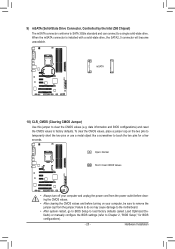
... When the mSATA connector is installed with a solid-state drive, the SATA2_5 connector will become unavailable. Failure to do so may cause damage to the motherboard. •• After system restart, go to BIOS Setup to load factory defaults (select Load Optimized Defaults) or manually configure the BIOS settings (refer to...
... When the mSATA connector is installed with a solid-state drive, the SATA2_5 connector will become unavailable. Failure to do so may cause damage to the motherboard. •• After system restart, go to BIOS Setup to load factory defaults (select Load Optimized Defaults) or manually configure the BIOS settings (refer to...


