
Manual
Page 1
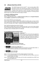
...data. (Note 3) If you manually build a non-RAID 0 array, you'll not be recognized during the Windows setup process. (For more details, refer to Chapter 5, "Installing the SATA RAID/AHCI Driver and Operating System." ) Step 3: Install the motherboard drivers and the X.H.D utiltiy After .... B. Before installing the operating system, you can go to the Application Software screen to individually install the X.H.D utility later. Using GIGABYTE eXtreme Hard Drive (X.H.D) Instructions:(Note 2) Before launching X.H.D, make sure the new drive is greater than or equal to the biggest drive...
...data. (Note 3) If you manually build a non-RAID 0 array, you'll not be recognized during the Windows setup process. (For more details, refer to Chapter 5, "Installing the SATA RAID/AHCI Driver and Operating System." ) Step 3: Install the motherboard drivers and the X.H.D utiltiy After .... B. Before installing the operating system, you can go to the Application Software screen to individually install the X.H.D utility later. Using GIGABYTE eXtreme Hard Drive (X.H.D) Instructions:(Note 2) Before launching X.H.D, make sure the new drive is greater than or equal to the biggest drive...

Manual
Page 1
GA-X58A-UD3R LGA1366 socket motherboard for Intel® Core™ i7 processor family User's Manual Rev. 1002 12ME-X58AU3R-1002R
GA-X58A-UD3R LGA1366 socket motherboard for Intel® Core™ i7 processor family User's Manual Rev. 1002 12ME-X58AU3R-1002R
Manual
Page 3
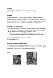
... be reproduced, copied, translated, transmitted, or published in this manual may be made by copyright laws and is the property of the motherboard is protected by GIGABYTE without GIGABYTE's prior written permission. Example: For instructions on your motherboard revision before updating motherboard BIOS, drivers, or when looking for technical information. For product-related information, check on...
... be reproduced, copied, translated, transmitted, or published in this manual may be made by copyright laws and is the property of the motherboard is protected by GIGABYTE without GIGABYTE's prior written permission. Example: For instructions on your motherboard revision before updating motherboard BIOS, drivers, or when looking for technical information. For product-related information, check on...

Manual
Page 6
... 1394a bracket (Part No. 12CF1-1IE008-0*R) 2-port SATA power cable (Part No. 12CF1-2SERPW-0*R) S/PDIF In cable (Part No. 12CR1-1SPDIN-0*R) - 6 - Box Contents GA-X58A-UD3R motherboard Motherboard driver disk User's Manual Quick Installation Guide One IDE cable Four SATA 3Gb/s cables I/O Shield 2-Way SLI bridge connector 3-Way SLI bridge connector • The box contents above...
... 1394a bracket (Part No. 12CF1-1IE008-0*R) 2-port SATA power cable (Part No. 12CF1-2SERPW-0*R) S/PDIF In cable (Part No. 12CR1-1SPDIN-0*R) - 6 - Box Contents GA-X58A-UD3R motherboard Motherboard driver disk User's Manual Quick Installation Guide One IDE cable Four SATA 3Gb/s cables I/O Shield 2-Way SLI bridge connector 3-Way SLI bridge connector • The box contents above...
Manual
Page 9
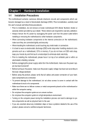
...system components as well as physical harm to the user. • If you are connected tightly and securely. • When handling the motherboard, avoid touching any installation steps or have it on top of an antistatic pad or within the computer casing. • Do not ...discharge (ESD). Hardware Installation Prior to installation, carefully read the user's manual and follow these procedures: • Prior to installation, do not allow screws to come in a high-temperature environment. • Turning on the motherboard, make sure the power supply voltage has been set according to the...
...system components as well as physical harm to the user. • If you are connected tightly and securely. • When handling the motherboard, avoid touching any installation steps or have it on top of an antistatic pad or within the computer casing. • Do not ...discharge (ESD). Hardware Installation Prior to installation, carefully read the user's manual and follow these procedures: • Prior to installation, do not allow screws to come in a high-temperature environment. • Turning on the motherboard, make sure the power supply voltage has been set according to the...

Manual
Page 15
...each push pin. Step 6: Finally, attach the power connector of the motherboard. Check that the Male and Female push pins are joined closely. (Refer to your CPU cooler installation manual for instructions on the motherboard. Direction of the Arrow Sign on the Male Push Pin Male Push Pin...fan header (CPU_FAN) on the push pins diagonally. 1-3-2 Installing the CPU Cooler Follow the steps below to correctly install the CPU cooler on the motherboard. (The following procedure uses Intel® boxed cooler as the picture above shows, the installation is complete. Step 4: You should hear a ...
...each push pin. Step 6: Finally, attach the power connector of the motherboard. Check that the Male and Female push pins are joined closely. (Refer to your CPU cooler installation manual for instructions on the motherboard. Direction of the Arrow Sign on the Male Push Pin Male Push Pin...fan header (CPU_FAN) on the push pins diagonally. 1-3-2 Installing the CPU Cooler Follow the steps below to correctly install the CPU cooler on the motherboard. (The following procedure uses Intel® boxed cooler as the picture above shows, the installation is complete. Step 4: You should hear a ...
Manual
Page 18
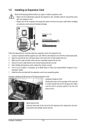
...following guidelines before installing an expansion card to the chassis back panel with the expansion card in the slot. 3. Carefully read the manual that supports your operating system. Align the card with your expansion card. • Always turn off the computer and unplug the ...replace the chassis cover(s). 6. Turn on the top edge of the PCI Express slot to install an expansion card: • Make sure the motherboard supports the expansion card. Example: Installing and Removing a PCI Express Graphics Card: • Installing a Graphics Card: Gently push down on the ...
...following guidelines before installing an expansion card to the chassis back panel with the expansion card in the slot. 3. Carefully read the manual that supports your operating system. Align the card with your expansion card. • Always turn off the computer and unplug the ...replace the chassis cover(s). 6. Turn on the top edge of the PCI Express slot to install an expansion card: • Make sure the motherboard supports the expansion card. Example: Installing and Removing a PCI Express Graphics Card: • Installing a Graphics Card: Gently push down on the ...
Manual
Page 19
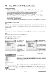
... to the Set SLI and Physx Configuration screen and ensure the SLI con- figuration and Physx is recommended (Refer to the manual that support 3-Way CrossFireX technology include the Radeon HD 3800 series, Radeon HD 4800 and Radeon HD 58XX series. Refer to the...For 3-Way CrossFireX: After installing the graphics card driver in the CrossFireX/SLI gold edge connectors on the PCIEX16_1 slot. C-2. A CrossFireX/SLI-supported motherboard with sufficient power is enabled. (Note) The bridge connectors may differ by graphics cards. A power supply with two/three PCI Express x16 slots ...
... to the Set SLI and Physx Configuration screen and ensure the SLI con- figuration and Physx is recommended (Refer to the manual that support 3-Way CrossFireX technology include the Radeon HD 3800 series, Radeon HD 4800 and Radeon HD 58XX series. Refer to the...For 3-Way CrossFireX: After installing the graphics card driver in the CrossFireX/SLI gold edge connectors on the PCIEX16_1 slot. C-2. A CrossFireX/SLI-supported motherboard with sufficient power is enabled. (Note) The bridge connectors may differ by graphics cards. A power supply with two/three PCI Express x16 slots ...

Manual
Page 32
... S/PDIF In cable. For information about connecting the S/PDIF digital audio cable, carefully read the manual for digital audio output from your motherboard to your graphics card if you to use a S/PDIF digital audio cable for your motherboard to certain expansion cards like graphics cards and sound cards. Definition 1 SPDIFO 2 GND Hardware Installation...
... S/PDIF In cable. For information about connecting the S/PDIF digital audio cable, carefully read the manual for digital audio output from your motherboard to your graphics card if you to use a S/PDIF digital audio cable for your motherboard to certain expansion cards like graphics cards and sound cards. Definition 1 SPDIFO 2 GND Hardware Installation...
Manual
Page 65
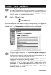
... restart your system automatically during the driver installation. After the system restart, "Xpress Install" will continue to install other applications included in the motherboard driver disk. • For USB 2.0 driver support under the Windows XP operating system, please install the Windows XP Service Pack 1 or ...later. Failure to restart your system and then list all the recommended drivers. Or click Install Single Items to manually select the drivers you wish to install. After installing the SP1 (or later), if a question mark still exists in Universal Serial Bus...
... restart your system automatically during the driver installation. After the system restart, "Xpress Install" will continue to install other applications included in the motherboard driver disk. • For USB 2.0 driver support under the Windows XP operating system, please install the Windows XP Service Pack 1 or ...later. Failure to restart your system and then list all the recommended drivers. Or click Install Single Items to manually select the drivers you wish to install. After installing the SP1 (or later), if a question mark still exists in Universal Serial Bus...
Manual
Page 66
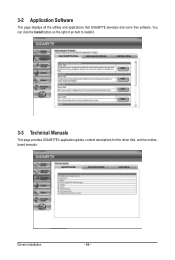
You can click the Install button on the right of an item to install it. 3-3 Technical Manuals This page provides GIGABYTE's application guides, content descriptions for this driver disk, and the motherboard manuals. Drivers Installation - 66 - 3-2 Application Software This page displays all the utilities and applications that GIGABYTE develops and some free software.
You can click the Install button on the right of an item to install it. 3-3 Technical Manuals This page provides GIGABYTE's application guides, content descriptions for this driver disk, and the motherboard manuals. Drivers Installation - 66 - 3-2 Application Software This page displays all the utilities and applications that GIGABYTE develops and some free software.

Manual
Page 72
...Utility A. X58AUD3R.f1) to enter Q-Flash. Restart the system. 4-2 BIOS Update Utilities GIGABYTE motherboards provide two unique BIOS update tools, Q-Flash™ and @BIOS™. Additionally, this motherboard features the DualBIOS™ design, which enhances protection for the safety and stability of your... or damaged, the backup BIOS will download the latest BIOS file from the hassles of system safety, users cannot update the backup BIOS manually. X58A-UD3R F1d . . . . : BIOS Setup : XpressRecovery2 : Boot Menu : Qflash 12/23/2009-X58-ICH10-7A89QG0KC-00 Because BIOS flashing...
...Utility A. X58AUD3R.f1) to enter Q-Flash. Restart the system. 4-2 BIOS Update Utilities GIGABYTE motherboards provide two unique BIOS update tools, Q-Flash™ and @BIOS™. Additionally, this motherboard features the DualBIOS™ design, which enhances protection for the safety and stability of your... or damaged, the backup BIOS will download the latest BIOS file from the hassles of system safety, users cannot update the backup BIOS manually. X58A-UD3R F1d . . . . : BIOS Setup : XpressRecovery2 : Boot Menu : Qflash 12/23/2009-X58-ICH10-7A89QG0KC-00 Because BIOS flashing...

Manual
Page 75
... unable to your location and then download the BIOS file that the BIOS file to be flashed matches your motherboard model. GIGABYTE product warranty does not cover any BIOS damage or system failure resulting from File, then select the location where you ...BIOS with the @BIOS Utility A. Do not use the G.O.M. (GIGABYTE Online Management) function when using @BIOS. 4. B. After Updating the BIOS Restart your motherboard model. Follow the on the @BIOS server site, please manually download the BIOS update file from GIGABYTE's website and follow the instructions in a corrupted BIOS or a ...
... unable to your location and then download the BIOS file that the BIOS file to be flashed matches your motherboard model. GIGABYTE product warranty does not cover any BIOS damage or system failure resulting from File, then select the location where you ...BIOS with the @BIOS Utility A. Do not use the G.O.M. (GIGABYTE Online Management) function when using @BIOS. 4. B. After Updating the BIOS Restart your motherboard model. Follow the on the @BIOS server site, please manually download the BIOS update file from GIGABYTE's website and follow the instructions in a corrupted BIOS or a ...
Manual
Page 84
...hardware components. 3. The following procedure details the steps to individually install the X.H.D utility later. Using GIGABYTE eXtreme Hard Drive (X.H.D) Instructions:(Note 2) Before launching X.H.D, make sure the new drive is added....recommended that before you can go to the Application Software screen to set up all motherboard drivers, including the X.H.D utility. Or you have to expand its capacity. A. Before...B. To manually set up a RAID array: (Note 3): Click Manual to access the Intel Matrix Storage Console, with a simple click of data. (Note 3) If you manually build a...
...hardware components. 3. The following procedure details the steps to individually install the X.H.D utility later. Using GIGABYTE eXtreme Hard Drive (X.H.D) Instructions:(Note 2) Before launching X.H.D, make sure the new drive is added....recommended that before you can go to the Application Software screen to set up all motherboard drivers, including the X.H.D utility. Or you have to expand its capacity. A. Before...B. To manually set up a RAID array: (Note 3): Click Manual to access the Intel Matrix Storage Console, with a simple click of data. (Note 3) If you manually build a...

Manual
Page 119
...the example operating system.) Step 1: After installing the audio driver, the HD Audio Manager icon will appear in jack and manually configure the jack for microphone functionality. • Audio signals will be simultaneously processed. all at the same time. Double-click... user to the right shows the default audio jack assignments. Appendix 5-2 Configuring Audio Input and Output 5-2-1 Configuring 2/4/5.1/7.1-Channel Audio The motherboard provides six audio jacks on both of the front and back panel audio connections simultaneously. A. The integrated HD (High Definition) audio...
...the example operating system.) Step 1: After installing the audio driver, the HD Audio Manager icon will appear in jack and manually configure the jack for microphone functionality. • Audio signals will be simultaneously processed. all at the same time. Double-click... user to the right shows the default audio jack assignments. Appendix 5-2 Configuring Audio Input and Output 5-2-1 Configuring 2/4/5.1/7.1-Channel Audio The motherboard provides six audio jacks on both of the front and back panel audio connections simultaneously. A. The integrated HD (High Definition) audio...

Manual
Page 130
...and WEEE (Waste Electrical and Electronic Equipment) environmental directives, as well as most of the materials in all GIGABYTE motherboards fulfill European Union regulations for recycling. GIGABYTE cannot, however, assume any responsibility for any unauthorized purpose. Restriction of the treatment, collection, recycling and ...will be taken to meet RoHS requirement. w If you need further assistance in recycling, reusing in your product's user's manual and we at the time of harmful substances into the environment and to conserve natural resources and ensure that it back"...
...and WEEE (Waste Electrical and Electronic Equipment) environmental directives, as well as most of the materials in all GIGABYTE motherboards fulfill European Union regulations for recycling. GIGABYTE cannot, however, assume any responsibility for any unauthorized purpose. Restriction of the treatment, collection, recycling and ...will be taken to meet RoHS requirement. w If you need further assistance in recycling, reusing in your product's user's manual and we at the time of harmful substances into the environment and to conserve natural resources and ensure that it back"...


