Manual
Page 1
GA-X48-DS4 LGA775 socket motherboard for Intel® CoreTM processor family/ Intel® Pentium® processor family/Intel® Celeron® processor family User's Manual Rev. 1301 12ME-X48DS4-1301R
GA-X48-DS4 LGA775 socket motherboard for Intel® CoreTM processor family/ Intel® Pentium® processor family/Intel® Celeron® processor family User's Manual Rev. 1301 12ME-X48DS4-1301R

Manual
Page 2
Motherboard GA-X48-DS4 Apr. 4, 2008 Motherboard GA-X48-DS4 Apr. 4, 2008
Motherboard GA-X48-DS4 Apr. 4, 2008 Motherboard GA-X48-DS4 Apr. 4, 2008
Manual
Page 3
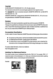
...; For detailed product information, carefully read the User's Manual. „ For instructions on how to use GIGABYTE's unique features, read or download the information on/from the Support\Motherboard\Technology Guide page on your motherboard revision before updating motherboard BIOS, drivers, or when looking for technical information. For example, "REV: 1.0" means the revision of...
...; For detailed product information, carefully read the User's Manual. „ For instructions on how to use GIGABYTE's unique features, read or download the information on/from the Support\Motherboard\Technology Guide page on your motherboard revision before updating motherboard BIOS, drivers, or when looking for technical information. For example, "REV: 1.0" means the revision of...

Manual
Page 4
Table of Contents Box Contents ...6 OptionalItems ...6 GA-X48-DS4 Motherboard Layout 7 Block Diagram ...8 Chapter 1 Hardware Installation 9 1-1 Installation Precautions 9 1-2 Product Specifications 10 1-3 Installing the CPU and CPU Cooler 13 1-3-1 Installing the CPU 13 1-3-2 Installing the CPU ...
Table of Contents Box Contents ...6 OptionalItems ...6 GA-X48-DS4 Motherboard Layout 7 Block Diagram ...8 Chapter 1 Hardware Installation 9 1-1 Installation Precautions 9 1-2 Product Specifications 10 1-3 Installing the CPU and CPU Cooler 13 1-3-1 Installing the CPU 13 1-3-2 Installing the CPU ...

Manual
Page 6
Box Contents GA-X48-DS4 motherboard Motherboard driver disk User's Manual Quick Installation Guide Intel® LGA775 CPU Installation Guide One IDE cable and one floppy disk drive cable Four SATA 3Gb/s cables One SATA bracket I/O Shield • The box contents above are subject to change without notice. • The motherboard image is for reference only and...
Box Contents GA-X48-DS4 motherboard Motherboard driver disk User's Manual Quick Installation Guide Intel® LGA775 CPU Installation Guide One IDE cable and one floppy disk drive cable Four SATA 3Gb/s cables One SATA bracket I/O Shield • The box contents above are subject to change without notice. • The motherboard image is for reference only and...
Manual
Page 7
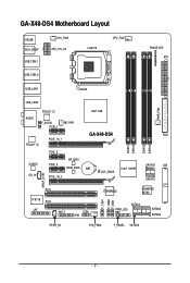
GA-X48-DS4 Motherboard Layout KB_MS RCA_SPDIF USB_1394_1 SYS_FAN1 ATX_12V_2X LGA775 CPU_FAN PHASE LED ATX USB_1394_2 USB_LAN1 USB_LAN2 AUDIO RTL8111C F_AUDIO PCIE_1 NB_FAN RTL8111C CODEC CD_IN PCIE_16_1 PCIE_2 PCIE_3 BP_BIOS MAIN_BIOS PCIE_16_2 Intel® X48 GA-X48-DS4 BAT CLR_CMOS Intel® ICH9R DDRII1 DDRII2 DDRII3 DDRII4 PWR_FAN FDD SATAII0 IDE SATAII1 SPDIF_O PCI1 IT8718 PCI2 LPT CI COM TPM F_1394 F_USB2 F_USB1 TSB43AB23 GIGABYTE SATA2 SATAII4 PWR_LED SATAII2 SATAII3 SPDIF_IN SYS_FAN2 F_PANEL SATAII5 - 7 -
GA-X48-DS4 Motherboard Layout KB_MS RCA_SPDIF USB_1394_1 SYS_FAN1 ATX_12V_2X LGA775 CPU_FAN PHASE LED ATX USB_1394_2 USB_LAN1 USB_LAN2 AUDIO RTL8111C F_AUDIO PCIE_1 NB_FAN RTL8111C CODEC CD_IN PCIE_16_1 PCIE_2 PCIE_3 BP_BIOS MAIN_BIOS PCIE_16_2 Intel® X48 GA-X48-DS4 BAT CLR_CMOS Intel® ICH9R DDRII1 DDRII2 DDRII3 DDRII4 PWR_FAN FDD SATAII0 IDE SATAII1 SPDIF_O PCI1 IT8718 PCI2 LPT CI COM TPM F_1394 F_USB2 F_USB1 TSB43AB23 GIGABYTE SATA2 SATAII4 PWR_LED SATAII2 SATAII3 SPDIF_IN SYS_FAN2 F_PANEL SATAII5 - 7 -

Manual
Page 9
...; It is best to the use of the product, please consult a certified computer technician. - 9 - Chapter 1 Hardware Installation 1-1 Installation Precautions The motherboard contains numerous delicate electronic circuits and components which can lead to damage to system components as well as physical harm to the user. • If...an ESD wrist strap, keep your hands dry and first touch a metal object to eliminate static electricity. • Prior to installing the motherboard, please have it on top of an antistatic pad or within the computer casing. • Do not place the computer system on ...
...; It is best to the use of the product, please consult a certified computer technician. - 9 - Chapter 1 Hardware Installation 1-1 Installation Precautions The motherboard contains numerous delicate electronic circuits and components which can lead to damage to system components as well as physical harm to the user. • If...an ESD wrist strap, keep your hands dry and first touch a metal object to eliminate static electricity. • Prior to installing the motherboard, please have it on top of an antistatic pad or within the computer casing. • Do not place the computer system on ...

Manual
Page 10
...Extreme Edition/Intel® Pentium® 4 processor/ Intel® Celeron® processor in the LGA 775 package (Go to GIGABYTE's website for the latest CPU support list.) Š L2 cache varies with CPU Š 1600/1333/1066/800 MHz FSB...Note 1) Š Dual channel memory architecture Š Support for DDR2 1200/1066/800/667 MHz memory modules (Go to GIGABYTE's website for the latest memory support list.) Š Support for ECC memory Š Realtek ALC889A codec Š High ... panel, 1 via the IEEE 1394a bracket connected to the internal IEEE 1394a header) GA-X48-DS4 Motherboard - 10 -
...Extreme Edition/Intel® Pentium® 4 processor/ Intel® Celeron® processor in the LGA 775 package (Go to GIGABYTE's website for the latest CPU support list.) Š L2 cache varies with CPU Š 1600/1333/1066/800 MHz FSB...Note 1) Š Dual channel memory architecture Š Support for DDR2 1200/1066/800/667 MHz memory modules (Go to GIGABYTE's website for the latest memory support list.) Š Support for ECC memory Š Realtek ALC889A codec Š High ... panel, 1 via the IEEE 1394a bracket connected to the internal IEEE 1394a header) GA-X48-DS4 Motherboard - 10 -

Manual
Page 12
Increase CPU voltage (Note 4) - Increase FSB voltage by 0.05V to 0.35V with 0.05V increment - GA-X48-DS4 Motherboard - 12 - Adjust PCI Express frequency from 100 MHz to 700 MHz with 0.05V increment - Increase (G)MCH voltage by 0.05V to 0.75V with 0.05V increment ...on the CPU being used. (Note 5) Due to chipset limitation, Intel ICH9R RAID driver does not support Windows 2000 operating system. Increase DDR2 voltage by motherboard model. (Note 4) The adjustable CPU voltage range depends on the CPU cooler you install. (Note 3) Available functions in BIOS Setup (CPU/DDR2/PCIe)...
Increase CPU voltage (Note 4) - Increase FSB voltage by 0.05V to 0.35V with 0.05V increment - GA-X48-DS4 Motherboard - 12 - Adjust PCI Express frequency from 100 MHz to 700 MHz with 0.05V increment - Increase (G)MCH voltage by 0.05V to 0.75V with 0.05V increment ...on the CPU being used. (Note 5) Due to chipset limitation, Intel ICH9R RAID driver does not support Windows 2000 operating system. Increase DDR2 voltage by motherboard model. (Note 4) The adjustable CPU voltage range depends on the CPU cooler you install. (Note 3) Available functions in BIOS Setup (CPU/DDR2/PCIe)...

Manual
Page 13
... socket.) • Apply an even and thin layer of thermal grease on the CPU. mended that the motherboard supports the CPU. (Go to GIGABYTE's website for the peripherals. Locate the alignment keys on the motherboard CPU socket and the notches on the surface of the CPU. • Do not turn off the computer...
... socket.) • Apply an even and thin layer of thermal grease on the CPU. mended that the motherboard supports the CPU. (Go to GIGABYTE's website for the peripherals. Locate the alignment keys on the motherboard CPU socket and the notches on the surface of the CPU. • Do not turn off the computer...

Manual
Page 14
... socket. CPU Socket Lever Step 1: Completely raise the CPU socket lever. Step 3: Lift the metal load plate on the CPU socket. GA-X48-DS4 Motherboard - 14 - Align the CPU pin one marking (triangle) with the pin one corner of the CPU socket (or you may align the CPU notches with ...
... socket. CPU Socket Lever Step 1: Completely raise the CPU socket lever. Step 3: Lift the metal load plate on the CPU socket. GA-X48-DS4 Motherboard - 14 - Align the CPU pin one marking (triangle) with the pin one corner of the CPU socket (or you may align the CPU notches with ...

Manual
Page 15
... cooler to your CPU cooler installation manual for instructions on installing the cooler.) Step 5: After the installation, check the back of the motherboard. Inadequately removing the CPU cooler may adhere to the CPU. Push down each push pin. Use extreme care when removing the CPU cooler...pin along the direction of the installed CPU. 1-3-2 Installing the CPU Cooler Follow the steps below to correctly install the CPU cooler on the motherboard. (The following procedure uses Intel® boxed cooler as the picture above, the installation is to install.) Step 3: Place the cooler atop ...
... cooler to your CPU cooler installation manual for instructions on installing the cooler.) Step 5: After the installation, check the back of the motherboard. Inadequately removing the CPU cooler may adhere to the CPU. Push down each push pin. Use extreme care when removing the CPU cooler...pin along the direction of the installed CPU. 1-3-2 Installing the CPU Cooler Follow the steps below to correctly install the CPU cooler on the motherboard. (The following procedure uses Intel® boxed cooler as the picture above, the installation is to install.) Step 3: Place the cooler atop ...

Manual
Page 16
... appear during the POST. Dual Channel mode cannot be installed in only one DDR2 memory module is operating in Dual Channel mode/performance. GA-X48-DS4 Motherboard - 16 - After the memory is installed, the BIOS will automatically detect the specifications and capacity of different capacity and chips are installed...two or four memory modules, it is recommended that memory of the same capacity, brand, speed, and chips be used . (Go to GIGABYTE's website for optimum performance. When memory modules of the memory. Four Modules DS/SS DS/SS DS/SS DDRII4 - Intel® Flex...
... appear during the POST. Dual Channel mode cannot be installed in only one DDR2 memory module is operating in Dual Channel mode/performance. GA-X48-DS4 Motherboard - 16 - After the memory is installed, the BIOS will automatically detect the specifications and capacity of different capacity and chips are installed...two or four memory modules, it is recommended that memory of the same capacity, brand, speed, and chips be used . (Go to GIGABYTE's website for optimum performance. When memory modules of the memory. Four Modules DS/SS DS/SS DS/SS DDRII4 - Intel® Flex...

Manual
Page 17
... direction. Step 2: The clips at both ends of the memory module. Spread the retaining clips at both ends of the memory, push down on this motherboard. Follow the steps below to install DDR2 DIMMs on the memory and insert it can only fit in the picture on the socket. Place the...
... direction. Step 2: The clips at both ends of the memory module. Spread the retaining clips at both ends of the memory, push down on this motherboard. Follow the steps below to install DDR2 DIMMs on the memory and insert it can only fit in the picture on the socket. Place the...

Manual
Page 18
...out from the slot. PCI Express x16 Slot PCI Express x1 Slot PCI Slot Follow the steps below to correctly install your operating system. GA-X48-DS4 Motherboard - 18 - 1-5 Installing an Expansion Card Read the following guidelines before installing an expansion card to make any required BIOS changes for your...the power cord from the chassis back panel. 2. Secure the card's metal bracket to install an expansion card: • Make sure the motherboard supports the expansion card. Turn on the card are completely inserted into the PCI Express x16 slot. If necessary, go to BIOS Setup ...
...out from the slot. PCI Express x16 Slot PCI Express x1 Slot PCI Slot Follow the steps below to correctly install your operating system. GA-X48-DS4 Motherboard - 18 - 1-5 Installing an Expansion Card Read the following guidelines before installing an expansion card to make any required BIOS changes for your...the power cord from the chassis back panel. 2. Secure the card's metal bracket to install an expansion card: • Make sure the motherboard supports the expansion card. Turn on the card are completely inserted into the PCI Express x16 slot. If necessary, go to BIOS Setup ...

Manual
Page 19
... SATA bracket and SATA power cable to prevent damage to hardware. • Insert the SATA signal cable and SATA power cable securely into to your motherboard. Before connecting the SATA signal cable, make sure to turn off your system and the power switch on Step 5: the bracket. the external SATA con...
... SATA bracket and SATA power cable to prevent damage to hardware. • Insert the SATA signal cable and SATA power cable securely into to your motherboard. Before connecting the SATA signal cable, make sure to turn off your system and the power switch on Step 5: the bracket. the external SATA con...

Manual
Page 20
... S/PDIF Out Connector This connector provides digital audio out to an external audio system that your device and then remove it from the motherboard. • When removing the cable, pull it side to side to an external audio system that your audio system provides an optical digital audio in connector. GA-X48-DS4 Motherboard - 20 -
... S/PDIF Out Connector This connector provides digital audio out to an external audio system that your device and then remove it from the motherboard. • When removing the cable, pull it side to side to an external audio system that your audio system provides an optical digital audio in connector. GA-X48-DS4 Motherboard - 20 -

Manual
Page 22
GA-X48-DS4 Motherboard - 22 - Unplug the power cord from the power outlet to prevent damage to the devices. • After installing the device and before connecting external devices: &#... devices and your devices are compliant with the connectors you wish to connect. • Before installing the devices, be sure to the connector on the motherboard. 1-8 Internal Connectors 4 1 3 23 2 7 6 12 5 22 24 9 13 15 8 21 10 18 14 19 20 4 17 16 11 9 1) ATX_12V_2X 2) ATX 3) CPU_FAN 4) SYS_FAN1/SYS_FAN2 5) PWR_FAN 6) NB_FAN 7) FDD...
GA-X48-DS4 Motherboard - 22 - Unplug the power cord from the power outlet to prevent damage to the devices. • After installing the device and before connecting external devices: &#... devices and your devices are compliant with the connectors you wish to connect. • Before installing the devices, be sure to the connector on the motherboard. 1-8 Internal Connectors 4 1 3 23 2 7 6 12 5 22 24 9 13 15 8 21 10 18 14 19 20 4 17 16 11 9 1) ATX_12V_2X 2) ATX 3) CPU_FAN 4) SYS_FAN1/SYS_FAN2 5) PWR_FAN 6) NB_FAN 7) FDD...

Manual
Page 23
...power supply providing a 2x4 12V and power connector, remove the protective covers from the 12V power connector and the main power connector on the motherboard. Do not insert the power supply cables into pins under the protective covers when using an Intel Extreme Edition CPU (130W). • ... in the correct orientation. Before connecting the power connector, first make sure the power supply is turned off and all the components on the motherboard. 1/2) ATX_12V_2X/ATX (2x4 12V Power Connector and 2x12 Main Power Connector) With the use of a power supply providing a 2x4 12V power...
...power supply providing a 2x4 12V and power connector, remove the protective covers from the 12V power connector and the main power connector on the motherboard. Do not insert the power supply cables into pins under the protective covers when using an Intel Extreme Edition CPU (130W). • ... in the correct orientation. Before connecting the power connector, first make sure the power supply is turned off and all the components on the motherboard. 1/2) ATX_12V_2X/ATX (2x4 12V Power Connector and 2x12 Main Power Connector) With the use of a power supply providing a 2x4 12V power...

Manual
Page 24
... These fan headers are designed with color-coded power connector wires. A red power connector wire indicates a positive connection and requires a +12V voltage. GA-X48-DS4 Motherboard - 24 - A red power connector wire indicates a positive connection and requires a +12V voltage. Definition 1 GND 1 2 +12V / Speed ... 3 NC • Be sure to connect fan cables to the fan headers to this header. 3/4/5) CPU_FAN/SYS_FAN1/SYS_FAN2/PWR_FAN (Fan Headers) The motherboard has a 4-pin CPU fan header (CPU_FAN), a 3-pin (SYS_FAN1) and a 4-pin (SYS_FAN2) system fan headers, and a 3-pin power ...
... These fan headers are designed with color-coded power connector wires. A red power connector wire indicates a positive connection and requires a +12V voltage. GA-X48-DS4 Motherboard - 24 - A red power connector wire indicates a positive connection and requires a +12V voltage. Definition 1 GND 1 2 +12V / Speed ... 3 NC • Be sure to connect fan cables to the fan headers to this header. 3/4/5) CPU_FAN/SYS_FAN1/SYS_FAN2/PWR_FAN (Fan Headers) The motherboard has a 4-pin CPU fan header (CPU_FAN), a 3-pin (SYS_FAN1) and a 4-pin (SYS_FAN2) system fan headers, and a 3-pin power ...


