User Guide
Page 1
... entering all of a RAID array, it should be at the C:\> command prompt and press ). System Requirements 1. At the diskpart prompt, type the following commands in BIOS Setup 4.
... entering all of a RAID array, it should be at the C:\> command prompt and press ). System Requirements 1. At the diskpart prompt, type the following commands in BIOS Setup 4.
User Guide
Page 2
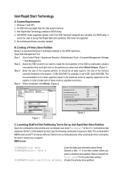
... store partition after entering S3 mode. "X" is complete, we recommend that disk) (Selects the specified volume. Save the settings and exit BIOS Setup. DISKPART>detail disk DISKPART>select volume X DISKPART>set id=84 override (Displays the properties of your computer. When you execute the ...last command where you to enter the BIOS Setup program. Restart your store partition. After the installation is volume of the selected disk and the volumes on that you to ...
... store partition after entering S3 mode. "X" is complete, we recommend that disk) (Selects the specified volume. Save the settings and exit BIOS Setup. DISKPART>detail disk DISKPART>select volume X DISKPART>set id=84 override (Displays the properties of your computer. When you execute the ...last command where you to enter the BIOS Setup program. Restart your store partition. After the installation is volume of the selected disk and the volumes on that you to ...
User Guide
Page 3
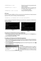
... will be output from the speaker. Restart your system is waked up and no sound will not light up . Intel Smart Connect Technology enabled in BIOS Setup 2. System Requirements 1.
... will be output from the speaker. Restart your system is waked up and no sound will not light up . Intel Smart Connect Technology enabled in BIOS Setup 2. System Requirements 1.
User Guide
Page 5
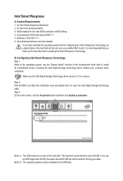
... the operating system, use an SSD larger than 64 GB, the space beyond 64 GB can still be used for the Intel SATA controllers in BIOS Setup 4. j k (Note 1) The SSD works as a cache of the motherboard driver disk to install all original data on the hard disk will be installed to...
... the operating system, use an SSD larger than 64 GB, the space beyond 64 GB can still be used for the Intel SATA controllers in BIOS Setup 4. j k (Note 1) The SSD works as a cache of the motherboard driver disk to install all original data on the hard disk will be installed to...
Manual
Page 3
...your motherboard looks like this manual may be made by any form or by GIGABYTE without GIGABYTE's prior written permission. „„ In order to their respective owners. For example, "REV: 1.0" ...means the revision of GIGABYTE. The trademarks mentioned in this : "REV: X.X." Disclaimer Information in the use of this manual...-related information, check on our website at: http://www.gigabyte.com Identifying Your Motherboard Revision The revision number on your motherboard revision before updating motherboard...
...your motherboard looks like this manual may be made by any form or by GIGABYTE without GIGABYTE's prior written permission. „„ In order to their respective owners. For example, "REV: 1.0" ...means the revision of GIGABYTE. The trademarks mentioned in this : "REV: X.X." Disclaimer Information in the use of this manual...-related information, check on our website at: http://www.gigabyte.com Identifying Your Motherboard Revision The revision number on your motherboard revision before updating motherboard...
Manual
Page 4
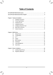
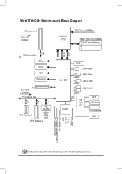
Table of Contents GA-Q77M-D2H Motherboard Layout 5 GA-Q77M-D2H Motherboard Block Diagram 6 Chapter 1 Hardware Installation 7 1-1 Installation Precautions 7 1-2 Product Specifications 8 1-3 Installing the CPU 11 1-4 Installing the Memory 12 1-5 Installing an Expansion Card 12 1-6 Back Panel Connectors 13 1-7 Internal Connectors 15 Chapter 2 BIOS Setup 24 2-1 Startup Screen 24 2-2 The Main Menu 25 2-3 M.I.T...26 2-4 System...33 2-5 BIOS Features 34 2-6 Peripherals...
Table of Contents GA-Q77M-D2H Motherboard Layout 5 GA-Q77M-D2H Motherboard Block Diagram 6 Chapter 1 Hardware Installation 7 1-1 Installation Precautions 7 1-2 Product Specifications 8 1-3 Installing the CPU 11 1-4 Installing the Memory 12 1-5 Installing an Expansion Card 12 1-6 Back Panel Connectors 13 1-7 Internal Connectors 15 Chapter 2 BIOS Setup 24 2-1 Startup Screen 24 2-2 The Main Menu 25 2-3 M.I.T...26 2-4 System...33 2-5 BIOS Features 34 2-6 Peripherals...
Manual
Page 5
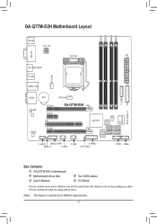
... ATX_12V LGA1155 ATX VGA_DVI SYS_FAN DP_HDMI_SPDIF R_USB USB30_LAN F_USB30 LPT AUDIO Intel GbE LAN BAT CPU_FAN PCIEX16 GA-Q77M-D2H PCIEX1 PCI CODEC PCIEX4 Intel® Q77 BIOS SATA3 01 SATA2 23 45 F_AUDIO DEBUG_PORT F_USB1 F_PANEL SPDIF_O F_USB2 CLR_CMOS COMA COMB iTE Super I/O... TPM IC (Note) Box Contents GA-Q77M-D2H motherboard Motherboard driver disk User's Manual Two SATA cables I/O Shield The box contents ...
... ATX_12V LGA1155 ATX VGA_DVI SYS_FAN DP_HDMI_SPDIF R_USB USB30_LAN F_USB30 LPT AUDIO Intel GbE LAN BAT CPU_FAN PCIEX16 GA-Q77M-D2H PCIEX1 PCI CODEC PCIEX4 Intel® Q77 BIOS SATA3 01 SATA2 23 45 F_AUDIO DEBUG_PORT F_USB1 F_PANEL SPDIF_O F_USB2 CLR_CMOS COMA COMB iTE Super I/O... TPM IC (Note) Box Contents GA-Q77M-D2H motherboard Motherboard driver disk User's Manual Two SATA cables I/O Shield The box contents ...
Manual
Page 6
GA-Q77M-D2H Motherboard Block Diagram 1 PCI Express x16 PCIe CLK (100 MHz) LGA1155 CPU CPU CLK+/- (100 MHz) DDR3 1600/1333/1066 MHz Dual Channel Memory DMI 2.0 ... 1 PCI PCIe CLK (100 MHz) PCI Express Bus x1 x4 x1 Intel GbE LAN 1 PCI Express x1 RJ45 LAN 1 PCI Express x4 Intel® Q77 BIOS 2 SATA 6Gb/s 4 SATA 3Gb/s 4 USB 3.0/2.0 8 USB 2.0/1.1 LPC Bus CODEC iTE Super I/O LPT COM Ports PS/2 KB/Mouse TPM Surround Speaker Out Center/Subwoofer Speaker Out...
GA-Q77M-D2H Motherboard Block Diagram 1 PCI Express x16 PCIe CLK (100 MHz) LGA1155 CPU CPU CLK+/- (100 MHz) DDR3 1600/1333/1066 MHz Dual Channel Memory DMI 2.0 ... 1 PCI PCIe CLK (100 MHz) PCI Express Bus x1 x4 x1 Intel GbE LAN 1 PCI Express x1 RJ45 LAN 1 PCI Express x4 Intel® Q77 BIOS 2 SATA 6Gb/s 4 SATA 3Gb/s 4 USB 3.0/2.0 8 USB 2.0/1.1 LPC Bus CODEC iTE Super I/O LPT COM Ports PS/2 KB/Mouse TPM Surround Speaker Out Center/Subwoofer Speaker Out...
Manual
Page 10
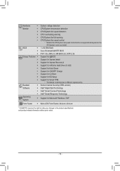
... EZ Setup Support for Microsoft® Windows 7/XP Micro ATX Form Factor; 24.4cm x 24.4cm * GIGABYTE reserves the right to make any changes to different regional policy. Hardware Š Monitor Š Š Š Š Š BIOS Š Š Š Unique Features Š Š Š Š Š Š Š Š Š Bundled...
... EZ Setup Support for Microsoft® Windows 7/XP Micro ATX Form Factor; 24.4cm x 24.4cm * GIGABYTE reserves the right to make any changes to different regional policy. Hardware Š Monitor Š Š Š Š Š BIOS Š Š Š Unique Features Š Š Š Š Š Š Š Š Š Bundled...
Manual
Page 12
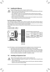
... Channel memory mode will automatically detect the specifications and capacity of the same capacity, brand, speed, and chips be used . (Go to GIGABYTE's website for the latest supported memory speeds and memory modules.) •• Always turn off the computer and unplug the power cord from ...when enabling Dual Channel mode with two memory modules, we recommend that came with two or four memory modules, it is installed, the BIOS will double the original memory bandwidth. Carefully read the following guidelines before you begin to insert the memory, switch the direction. If you...
... Channel memory mode will automatically detect the specifications and capacity of the same capacity, brand, speed, and chips be used . (Go to GIGABYTE's website for the latest supported memory speeds and memory modules.) •• Always turn off the computer and unplug the power cord from ...when enabling Dual Channel mode with two memory modules, we recommend that came with two or four memory modules, it is installed, the BIOS will double the original memory bandwidth. Carefully read the following guidelines before you begin to insert the memory, switch the direction. If you...
Manual
Page 14
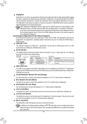
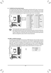
... speakers in a 5.1/7.1-channel audio configuration. In addition to the default speakers settings, the ~ audio jacks can support a maximum resolution of 2560x1600 but not during the BIOS Setup or POST process. Only microphones still MUST be reconfigured to perform different functions via the audio software. USB 2.0/1.1 Port The USB port supports the...
... speakers in a 5.1/7.1-channel audio configuration. In addition to the default speakers settings, the ~ audio jacks can support a maximum resolution of 2560x1600 but not during the BIOS Setup or POST process. Only microphones still MUST be reconfigured to perform different functions via the audio software. USB 2.0/1.1 Port The USB port supports the...
Manual
Page 17
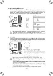
... CPU_FAN: Pin No. 3/4) CPU_FAN/SYS_FAN (Fan Headers) All fan headers on the headers. 5) BAT (Battery) The battery provides power to keep the values (such as BIOS configurations, date, and time information) in accordance with fan speed control design. Most fan headers possess a foolproof insertion design. Definition 1 GND 2 +12V 3 Sense 4 Speed Control...
... CPU_FAN: Pin No. 3/4) CPU_FAN/SYS_FAN (Fan Headers) All fan headers on the headers. 5) BAT (Battery) The battery provides power to keep the values (such as BIOS configurations, date, and time information) in accordance with fan speed control design. Most fan headers possess a foolproof insertion design. Definition 1 GND 2 +12V 3 Sense 4 Speed Control...
Manual
Page 19
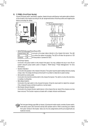
... the speaker on the chassis front panel. You may differ by issuing a beep code. When connecting your system using the power switch (refer to Chapter 2, "BIOS Setup," "Power Management," for more information). •• Speaker (Speaker): Connects to the power switch on the chassis front panel. Message/Power/ Sleep LED Power...
... the speaker on the chassis front panel. You may differ by issuing a beep code. When connecting your system using the power switch (refer to Chapter 2, "BIOS Setup," "Power Management," for more information). •• Speaker (Speaker): Connects to the power switch on the chassis front panel. Message/Power/ Sleep LED Power...
Manual
Page 20
... has different wire assignments, please contact the chassis manufacturer. Definition 1 SPDIFO 1 2 GND F_PANEL (H61M-D2) ACPI_CPT (GA-IVB) SMB_CPT (GA-IVB) CLR_CMOS CI DIS_ME GP15_CPT (GA-IVB) Voltage measurement points(G1.Sniper 3) BIOS Switcher (SW4) XDP_CPU XDP_PCH (GA-IVB) - 20 - For information about connecting the S/PDIF digital audio cable, carefully read the manual for your...
... has different wire assignments, please contact the chassis manufacturer. Definition 1 SPDIFO 1 2 GND F_PANEL (H61M-D2) ACPI_CPT (GA-IVB) SMB_CPT (GA-IVB) CLR_CMOS CI DIS_ME GP15_CPT (GA-IVB) Voltage measurement points(G1.Sniper 3) BIOS Switcher (SW4) XDP_CPU XDP_PCH (GA-IVB) - 20 - For information about connecting the S/PDIF digital audio cable, carefully read the manual for your...
Manual
Page 21
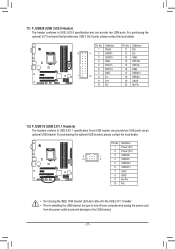
.... Each USB header can provide two USB ports. DIP 1 23 PCIe power connector (SATA)(X58A-OC) DIP 1 23 1 F_USB30 TPM w/housing PWM Switch (X58A-OC) BIOS Switcher (X58A-OC) 1 M_S Voltage measurement module(X58A-OC) DIP 1 23 1 11) F_USB30 (USB 3.0/2.0 Header) DIP The header conforms to USB 3.0/2.0 specification and can provide...
.... Each USB header can provide two USB ports. DIP 1 23 PCIe power connector (SATA)(X58A-OC) DIP 1 23 1 F_USB30 TPM w/housing PWM Switch (X58A-OC) BIOS Switcher (X58A-OC) 1 M_S Voltage measurement module(X58A-OC) DIP 1 23 1 11) F_USB30 (USB 3.0/2.0 Header) DIP The header conforms to USB 3.0/2.0 specification and can provide...
Manual
Page 23
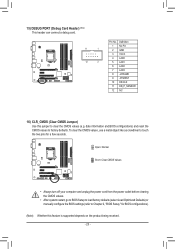
...the power outlet before clearing the CMOS values. •• After system restart, go to BIOS Setup to load factory defaults (select Load Optimized Defaults) or manually configure the BIOS settings (refer to Chapter 2, "BIOS Setup," for a few seconds. 15) DEBUG PORT (Debug Card Header) (Note) This header... CLR_CMOS (Clear CMOS Jumper) Use this feature is supported depends on the product being received. - 23 - date information and BIOS configurations) and reset the CMOS values to touch the two pins for BIOS configurations). (Note) Whether this jumper to clear the CMOS values (e.g.
...the power outlet before clearing the CMOS values. •• After system restart, go to BIOS Setup to load factory defaults (select Load Optimized Defaults) or manually configure the BIOS settings (refer to Chapter 2, "BIOS Setup," for a few seconds. 15) DEBUG PORT (Debug Card Header) (Note) This header... CLR_CMOS (Clear CMOS Jumper) Use this feature is supported depends on the product being received. - 23 - date information and BIOS configurations) and reset the CMOS values to touch the two pins for BIOS configurations). (Note) Whether this jumper to clear the CMOS values (e.g.
Manual
Page 24
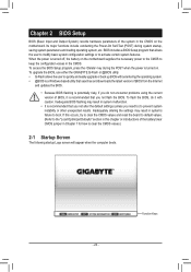
... malfunction. •• It is recommended that you not flash the BIOS. BIOS includes a BIOS Setup program that searches and downloads the latest version of BIOS from the Internet and updates the BIOS. •• Because BIOS flashing is potentially risky, if you need to) to clear the CMOS... values.) 2-1 Startup Screen The following startup Logo screen will appear when the computer boots. - 24 - To upgrade the BIOS, use either the GIGABYTE Q-Flash or @BIOS utility. •• Q-Flash allows the user to keep the configuration values in Chapter 1 for how to prevent system ...
... malfunction. •• It is recommended that you not flash the BIOS. BIOS includes a BIOS Setup program that searches and downloads the latest version of BIOS from the Internet and updates the BIOS. •• Because BIOS flashing is potentially risky, if you need to) to clear the CMOS... values.) 2-1 Startup Screen The following startup Logo screen will appear when the computer boots. - 24 - To upgrade the BIOS, use either the GIGABYTE Q-Flash or @BIOS utility. •• Q-Flash allows the user to keep the configuration values in Chapter 1 for how to prevent system ...
Manual
Page 25
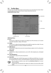
..., integrated audio, and integrated LAN, etc. „„ Power Management Use this menu to its defaults. •• The BIOS Setup menus described in the BIOS Setup program to the CMOS and exit BIOS Setup. 2-2 The Main Menu On the main menu of your CPU and memory, etc. You can use your system... program, press arrow keys to move among the items and press to configure the default language used by BIOS version. - 25 - Use this menu to configure all the power-saving functions. „„ Save & Exit Save all peripheral devices, such as usual, select the ...
..., integrated audio, and integrated LAN, etc. „„ Power Management Use this menu to its defaults. •• The BIOS Setup menus described in the BIOS Setup program to the CMOS and exit BIOS Setup. 2-2 The Main Menu On the main menu of your CPU and memory, etc. You can use your system... program, press arrow keys to move among the items and press to configure the default language used by BIOS version. - 25 - Use this menu to configure all the power-saving functions. „„ Save & Exit Save all peripheral devices, such as usual, select the ...
Manual
Page 26
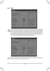
... memory and reduce the useful life of these components. 2-3 M.I.T. This page is for advanced users only and we recommend you made is dependent on the BIOS version, CPU base clock, CPU frequency, memory frequency, total memory size, CPU temperature, Vcore, and memory voltage. - 26 - Incorrectly doing overclock/overvoltage may result in...
... memory and reduce the useful life of these components. 2-3 M.I.T. This page is for advanced users only and we recommend you made is dependent on the BIOS version, CPU base clock, CPU frequency, memory frequency, total memory size, CPU temperature, Vcore, and memory voltage. - 26 - Incorrectly doing overclock/overvoltage may result in...
Manual
Page 28
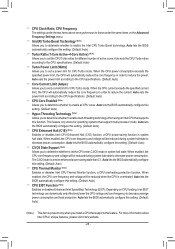
...Advanced Frequency Settings menu. && Intel(R) Turbo Boost Technology (Note) Allows you to determine whether to enable all CPU cores. Auto lets the BIOS automatically configure this setting. (Default: Auto) && CPU Enhanced Halt (C1E) (Note) Enables or disables Intel CPU Enhanced Halt (C1E) ...function, a CPU power-saving function in system halt state. Auto lets the BIOS automatically configure this setting. (Default: Auto) && CPU Thermal Monitor (Note) Enables or disables Intel CPU Thermal Monitor function, a CPU overheating ...
...Advanced Frequency Settings menu. && Intel(R) Turbo Boost Technology (Note) Allows you to determine whether to enable all CPU cores. Auto lets the BIOS automatically configure this setting. (Default: Auto) && CPU Enhanced Halt (C1E) (Note) Enables or disables Intel CPU Enhanced Halt (C1E) ...function, a CPU power-saving function in system halt state. Auto lets the BIOS automatically configure this setting. (Default: Auto) && CPU Thermal Monitor (Note) Enables or disables Intel CPU Thermal Monitor function, a CPU overheating ...


