Manual
Page 1
GA-PA65-UD3-B3 LGA1155 socket motherboard for Intel® Core™ i7 processors/ Intel® Core™ i5 processors/Intel® Core™ i3 processors/ Intel® Pentium® processors/Intel® Celeron® processors User's Manual Rev. 1002
GA-PA65-UD3-B3 LGA1155 socket motherboard for Intel® Core™ i7 processors/ Intel® Core™ i5 processors/Intel® Core™ i3 processors/ Intel® Pentium® processors/Intel® Celeron® processors User's Manual Rev. 1002
Manual
Page 3
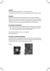
The trademarks mentioned in this : "REV: X.X." For product-related information, check on our website at: http://www.gigabyte.com Identifying Your Motherboard Revision The revision number on your motherboard revision before updating motherboard BIOS, drivers, or when looking for technical information. All rights reserved. Example: Disclaimer Information in any form or by any means without...
The trademarks mentioned in this : "REV: X.X." For product-related information, check on our website at: http://www.gigabyte.com Identifying Your Motherboard Revision The revision number on your motherboard revision before updating motherboard BIOS, drivers, or when looking for technical information. All rights reserved. Example: Disclaimer Information in any form or by any means without...
Manual
Page 4
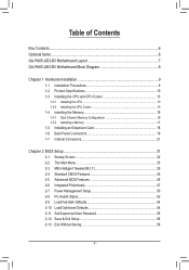
Table of Contents Box Contents...6 Optional Items...6 GA-PA65-UD3-B3 Motherboard Layout 7 GA-PA65-UD3-B3 Motherboard Block Diagram 8 Chapter 1 Hardware Installation 9 1-1 Installation Precautions 9 1-2 Product Specifications 10 1-3 Installing the CPU and CPU Cooler 13 1-3-1 Installing the CPU 13 1-3-2 Installing the CPU Cooler ...
Table of Contents Box Contents...6 Optional Items...6 GA-PA65-UD3-B3 Motherboard Layout 7 GA-PA65-UD3-B3 Motherboard Block Diagram 8 Chapter 1 Hardware Installation 9 1-1 Installation Precautions 9 1-2 Product Specifications 10 1-3 Installing the CPU and CPU Cooler 13 1-3-1 Installing the CPU 13 1-3-2 Installing the CPU Cooler ...
Manual
Page 6
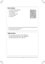
Box Contents GA-PA65-UD3-B3 motherboard Motherboard driver disk User's Manual Quick Installation Guide Two SATA cables I/O Shield • The box contents above are subject to change without notice. • The motherboard image is for reference only and the actual items shall depend on the product package you obtain. Optional Items 2-port USB 2.0 bracket (Part No. 12CR1-1UB030-5*R) 2-port SATA power cable (Part No. 12CF1-2SERPW-0*R) COM port cable (Part No. 12CF1-1CM001-3*R) - 6 - The box contents are for reference only.
Box Contents GA-PA65-UD3-B3 motherboard Motherboard driver disk User's Manual Quick Installation Guide Two SATA cables I/O Shield • The box contents above are subject to change without notice. • The motherboard image is for reference only and the actual items shall depend on the product package you obtain. Optional Items 2-port USB 2.0 bracket (Part No. 12CR1-1UB030-5*R) 2-port SATA power cable (Part No. 12CF1-2SERPW-0*R) COM port cable (Part No. 12CF1-1CM001-3*R) - 6 - The box contents are for reference only.
Manual
Page 7
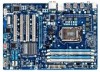
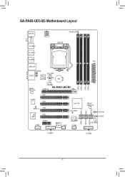
GA-PA65-UD3-B3 Motherboard Layout COAXIAL KB_MS R_USB_2 R_USB_1 R_USB30 ATX_12V PHASE_LED LGA1155 USB_LAN F_AUDIO AUDIO SYS_FAN1 Etron EJ168 PWR_FAN BAT Realtek RTL8111E CPU_FAN GA-PA65-UD3-B3 PCIEX16 PCI1 CODEC PCI2 Intel® H61 iTE IT8728 SPDIF_O PCI3 PCI4 COMA PCIEX1 CLR_CMOS Etron EJ168 F_USB2 PCIe to PCI Bridge F_USB1 SATA2_2 SATA2_0 GSATA3_4 SATA2_3 SATA2_1 GSATA3_5 DDR3_1 DDR3_2 DDR3_3 DDR3_4 ATX Marvell 88SE9172 M_BIOS B_BIOS SYS_FAN2 F_USB30 F_PANEL - 7 -
GA-PA65-UD3-B3 Motherboard Layout COAXIAL KB_MS R_USB_2 R_USB_1 R_USB30 ATX_12V PHASE_LED LGA1155 USB_LAN F_AUDIO AUDIO SYS_FAN1 Etron EJ168 PWR_FAN BAT Realtek RTL8111E CPU_FAN GA-PA65-UD3-B3 PCIEX16 PCI1 CODEC PCI2 Intel® H61 iTE IT8728 SPDIF_O PCI3 PCI4 COMA PCIEX1 CLR_CMOS Etron EJ168 F_USB2 PCIe to PCI Bridge F_USB1 SATA2_2 SATA2_0 GSATA3_4 SATA2_3 SATA2_1 GSATA3_5 DDR3_1 DDR3_2 DDR3_3 DDR3_4 ATX Marvell 88SE9172 M_BIOS B_BIOS SYS_FAN2 F_USB30 F_PANEL - 7 -
Manual
Page 8
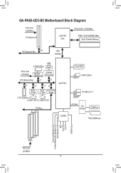
GA-PA65-UD3-B3 Motherboard Block Diagram PCIe CLK (100 MHz) 1 PCI Express x16 LGA1155 CPU CPU CLK+/- (100 MHz) DDR3 1333/1066/800 MHz Dual Channel Memory PCI Express ...
GA-PA65-UD3-B3 Motherboard Block Diagram PCIe CLK (100 MHz) 1 PCI Express x16 LGA1155 CPU CPU CLK+/- (100 MHz) DDR3 1333/1066/800 MHz Dual Channel Memory PCI Express ...
Manual
Page 9
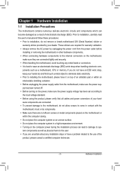
...an ESD wrist strap, keep your hands dry and first touch a metal object to eliminate static electricity. •• Prior to installing the motherboard, please have a problem related to wear an electrostatic discharge (ESD) wrist strap when handling electronic com- These stickers are required for warranty ..., carefully read the user's manual and follow these procedures: •• Prior to installation, do not remove or break motherboard S/N (Serial Number) sticker or warranty sticker provided by unplugging the power cord from the power outlet before installing or removing the...
...an ESD wrist strap, keep your hands dry and first touch a metal object to eliminate static electricity. •• Prior to installing the motherboard, please have a problem related to wear an electrostatic discharge (ESD) wrist strap when handling electronic com- These stickers are required for warranty ..., carefully read the user's manual and follow these procedures: •• Prior to installation, do not remove or break motherboard S/N (Serial Number) sticker or warranty sticker provided by unplugging the power cord from the power outlet before installing or removing the...
Manual
Page 12
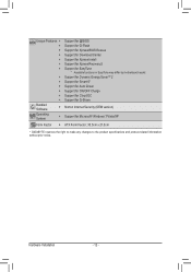
...;Š Support for Xpress Install ŠŠ Support for Xpress Recovery2 ŠŠ Support for EasyTune * Available functions in EasyTune may differ by motherboard model. ŠŠ Support for Dynamic Energy Saver™ 2 ŠŠ Support for Smart 6™ ŠŠ Support for Auto Green...;Š Support for Microsoft® Windows 7/Vista/XP Form Factor ŠŠ ATX Form Factor; 30.5cm x 21.5cm * GIGABYTE reserves the right to make any changes to the product specifications and product-related information without prior notice. Hardware Installation - 12 -
...;Š Support for Xpress Install ŠŠ Support for Xpress Recovery2 ŠŠ Support for EasyTune * Available functions in EasyTune may differ by motherboard model. ŠŠ Support for Dynamic Energy Saver™ 2 ŠŠ Support for Smart 6™ ŠŠ Support for Auto Green...;Š Support for Microsoft® Windows 7/Vista/XP Form Factor ŠŠ ATX Form Factor; 30.5cm x 21.5cm * GIGABYTE reserves the right to make any changes to the product specifications and product-related information without prior notice. Hardware Installation - 12 -
Manual
Page 13
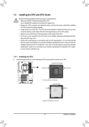
... host frequency in accordance with the CPU specifications. Locate the alignment keys on the motherboard CPU socket and the notches on the computer if the CPU cooler is not recommended that the motherboard supports the CPU. (Go to GIGABYTE's website for the peripherals. Hardware Installation 1-3 Installing the CPU and CPU Cooler Read the...
... host frequency in accordance with the CPU specifications. Locate the alignment keys on the motherboard CPU socket and the notches on the computer if the CPU cooler is not recommended that the motherboard supports the CPU. (Go to GIGABYTE's website for the peripherals. Hardware Installation 1-3 Installing the CPU and CPU Cooler Read the...
Manual
Page 14
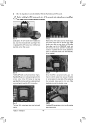
....) Step 3: Hold the CPU with the socket alignment keys) and gently insert the CPU into position. Step 5: Push the CPU socket lever back into the motherboard CPU socket. NOTE: Hold the CPU socket lever by the handle, not the lever base portion. Follow the steps below to the CPU. When replacing...
....) Step 3: Hold the CPU with the socket alignment keys) and gently insert the CPU into position. Step 5: Push the CPU socket lever back into the motherboard CPU socket. NOTE: Hold the CPU socket lever by the handle, not the lever base portion. Follow the steps below to the CPU. When replacing...

Manual
Page 15
... and CPU may damage the CPU. - 15 - 1-3-2 Installing the CPU Cooler Follow the steps below to correctly install the CPU cooler on the motherboard. (The following procedure uses Intel® boxed cooler as the picture above shows, the installation is to install.) Step 3: Place the cooler atop ...the CPU, aligning the four push pins through the pin holes on the motherboard. Step 4: You should hear a "click" when pushing down on the push pins diagonally. Step 2: Before installing the cooler, note the direction of...
... and CPU may damage the CPU. - 15 - 1-3-2 Installing the CPU Cooler Follow the steps below to correctly install the CPU cooler on the motherboard. (The following procedure uses Intel® boxed cooler as the picture above shows, the installation is to install.) Step 3: Place the cooler atop ...the CPU, aligning the four push pins through the pin holes on the motherboard. Step 4: You should hear a "click" when pushing down on the push pins diagonally. Step 2: Before installing the cooler, note the direction of...
Manual
Page 16
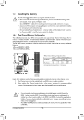
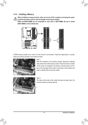
...Channel memory mode will be installed in the DDR3_1 and DDR3_3 sockets. SS DDR3_4 - Dual Channel mode cannot be used . (Go to GIGABYTE's website for optimum performance. • If one direction. When enabling Dual Channel mode with two or four memory modules, it /them... Make sure that memory of them in Dual Channel mode. 1. If three single-sided memory modules are to install it is recommended that the motherboard supports the memory. Hardware Installation - 16 - 1-4 Installing the Memory Read the following : Channel 0: DDR3_1, DDR3_2 Channel 1: DDR3_3, DDR3_4 ...
...Channel memory mode will be installed in the DDR3_1 and DDR3_3 sockets. SS DDR3_4 - Dual Channel mode cannot be used . (Go to GIGABYTE's website for optimum performance. • If one direction. When enabling Dual Channel mode with two or four memory modules, it /them... Make sure that memory of them in Dual Channel mode. 1. If three single-sided memory modules are to install it is recommended that the motherboard supports the memory. Hardware Installation - 16 - 1-4 Installing the Memory Read the following : Channel 0: DDR3_1, DDR3_2 Channel 1: DDR3_3, DDR3_4 ...
Manual
Page 17
... DIMM A DDR3 memory module has a notch, so it vertically into place when the memory module is securely inserted. - 17 - Place the memory module on this motherboard. Hardware Installation Follow the steps below to the memory module. As indicated in the picture on the left, place your memory modules in one direction...
... DIMM A DDR3 memory module has a notch, so it vertically into place when the memory module is securely inserted. - 17 - Place the memory module on this motherboard. Hardware Installation Follow the steps below to the memory module. As indicated in the picture on the left, place your memory modules in one direction...
Manual
Page 18
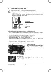
... the card and then pull the card straight up from the power outlet before you begin to install an expansion card: • Make sure the motherboard supports the expansion card. PCI Express x16 slot PCI slot PCI Express x1 slot Follow the steps below to correctly install your expansion card in...
... the card and then pull the card straight up from the power outlet before you begin to install an expansion card: • Make sure the motherboard supports the expansion card. PCI Express x16 slot PCI slot PCI Express x1 slot Follow the steps below to correctly install your expansion card in...
Manual
Page 19
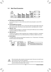
... 3.0 port supports the USB 3.0 specification and is occurring •• When removing the cable connected to a back panel connector, first remove the cable from the motherboard. •• When removing the cable, pull it side to side to prevent an electrical short inside the cable connector. - 19 - RJ-45 LAN Port...
... 3.0 port supports the USB 3.0 specification and is occurring •• When removing the cable connected to a back panel connector, first remove the cable from the motherboard. •• When removing the cable, pull it side to side to prevent an electrical short inside the cable connector. - 19 - RJ-45 LAN Port...

Manual
Page 21
... 9 9) F_PANEL 10) F_AUDIO 11) SPDIF_O 12) F_USB1/F_USB2 13) F_USB30 14) COMA 15) CLR_CMOS 16) PHASE LED Read the following guidelines before turning on the motherboard. - 21 -
... 9 9) F_PANEL 10) F_AUDIO 11) SPDIF_O 12) F_USB1/F_USB2 13) F_USB30 14) COMA 15) CLR_CMOS 16) PHASE LED Read the following guidelines before turning on the motherboard. - 21 -
Manual
Page 22
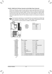
... will not start. Connect the power supply cable to the CPU. If the 12V power connector is turned off and all the components on the motherboard. The 12V power connector mainly supplies power to the power connector in the correct orientation. If a power supply is recommended that a power supply that does...
... will not start. Connect the power supply cable to the CPU. If the 12V power connector is turned off and all the components on the motherboard. The 12V power connector mainly supplies power to the power connector in the correct orientation. If a power supply is recommended that a power supply that does...

Manual
Page 23
...For optimum heat dissipation, it in the power cord and restart your computer. •• Always turn off . 3/4/5) CPU_FAN/SYS_FAN1/SYS_FAN2/PWR_FAN (Fan Headers) The motherboard has a 4-pin CPU fan header (CPU_FAN), a 4-pin (SYS_FAN2) and a 3-pin (SYS_FAN1) system fan headers, and a 3-pin power fan header (PWR_FAN... computer is replaced with an equivalent one minute. (Or use of the battery holder, making them short for one . The motherboard supports CPU fan speed control, which requires the use a metal object like a screwdriver to replace the battery by removing the ...
...For optimum heat dissipation, it in the power cord and restart your computer. •• Always turn off . 3/4/5) CPU_FAN/SYS_FAN1/SYS_FAN2/PWR_FAN (Fan Headers) The motherboard has a 4-pin CPU fan header (CPU_FAN), a 4-pin (SYS_FAN2) and a 3-pin (SYS_FAN1) system fan headers, and a 3-pin power fan header (PWR_FAN... computer is replaced with an equivalent one minute. (Or use of the battery holder, making them short for one . The motherboard supports CPU fan speed control, which requires the use a metal object like a screwdriver to replace the battery by removing the ...

Manual
Page 26
... graphics cards may connect your expansion card. Incorrect connection between the module connector and the motherboard header will be present on each wire instead of the motherboard header. For information about connecting the front panel audio module that has separated connectors on ...10 NC •• The front panel audio header supports HD audio by expansion cards) for digital audio output from your motherboard to your motherboard to Chapter 5, "Configuring 2/4/5.1/7.1-Channel Audio." •• Some chassis provide a front panel audio module that has different wire ...
... graphics cards may connect your expansion card. Incorrect connection between the module connector and the motherboard header will be present on each wire instead of the motherboard header. For information about connecting the front panel audio module that has separated connectors on ...10 NC •• The front panel audio header supports HD audio by expansion cards) for digital audio output from your motherboard to your motherboard to Chapter 5, "Configuring 2/4/5.1/7.1-Channel Audio." •• Some chassis provide a front panel audio module that has different wire ...
Manual
Page 28
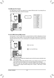
... the two pins or use a metal object like a screwdriver to Chapter 2, "BIOS Setup," for a few seconds. Failure to do so may cause damage to the motherboard. •• After system restart, go to BIOS Setup to load factory defaults (select Load Optimized Defaults) or manually configure the BIOS settings (refer to...
... the two pins or use a metal object like a screwdriver to Chapter 2, "BIOS Setup," for a few seconds. Failure to do so may cause damage to the motherboard. •• After system restart, go to BIOS Setup to load factory defaults (select Load Optimized Defaults) or manually configure the BIOS settings (refer to...


