Manual
Page 6
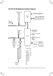
GA-P61-S3-B3 Motherboard Block Diagram 1 PCI Express x16 CPU CLK+/- (100 MHz) LGA1155 CPU DDR3 1333/1066/800 MHz Dual Channel Memory PCIe CLK (100 MHz) x16 PCI Express Bus DMI 2.0 2 PCI Express x1 PCI Express Bus x1 Atheros AR8151 x1 x1 PCIe to PCI Bridge RJ45 PCI Bus LAN Intel® H61 Dual BIOS 4 SATA 3Gb/s 8 USB 2.0/1.1 LPC Bus iTE IT8728 CODEC COM Port PS/2 KB/Mouse MIC (Center/Subwoofer Speaker Out) Line Out (Front Speaker Out) Line In (Rear Speaker Out) S/PDIF Out 3 PCI PCI CLK (33 MHz) - 6 -
GA-P61-S3-B3 Motherboard Block Diagram 1 PCI Express x16 CPU CLK+/- (100 MHz) LGA1155 CPU DDR3 1333/1066/800 MHz Dual Channel Memory PCIe CLK (100 MHz) x16 PCI Express Bus DMI 2.0 2 PCI Express x1 PCI Express Bus x1 Atheros AR8151 x1 x1 PCIe to PCI Bridge RJ45 PCI Bus LAN Intel® H61 Dual BIOS 4 SATA 3Gb/s 8 USB 2.0/1.1 LPC Bus iTE IT8728 CODEC COM Port PS/2 KB/Mouse MIC (Center/Subwoofer Speaker Out) Line Out (Front Speaker Out) Line In (Rear Speaker Out) S/PDIF Out 3 PCI PCI CLK (33 MHz) - 6 -
Manual
Page 12
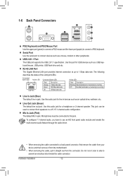
... No data transmission or receiving is occurring Line In Jack (Blue) The default line in a 4/5.1/7.1-channel audio configuration. Microphones must be used to connect front speakers in jack. Use this audio jack for USB devices such as a USB keyboard/mouse, USB printer, USB flash drive and etc. The following describes the... the cable, pull it side to side to 1 Gbps data rate. Serial Port Use the serial port to this audio jack for a headphone or 2-channel speaker.
... No data transmission or receiving is occurring Line In Jack (Blue) The default line in a 4/5.1/7.1-channel audio configuration. Microphones must be used to connect front speakers in jack. Use this audio jack for USB devices such as a USB keyboard/mouse, USB printer, USB flash drive and etc. The following describes the... the cable, pull it side to side to 1 Gbps data rate. Serial Port Use the serial port to this audio jack for a headphone or 2-channel speaker.
Manual
Page 16
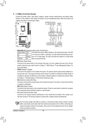
...The LED S0 On is on when the system is detected, the BIOS may differ by issuing a beep code. S1 Blinking tem is in S3/S4 sleep S3/S4/S5 Off state or powered off (S5). •• PW (Power Switch, Red): Connects to the power switch on the chassis ... issue beeps in different patterns to indicate the problem. A front panel module mainly consists of power switch, reset switch, power LED, hard drive activity LED, speaker and etc. RESRES+ CICI+ PWR+ PWR- The LED is in S1 sleep state. If a problem is operating. This function requires a chassis with a ...
...The LED S0 On is on when the system is detected, the BIOS may differ by issuing a beep code. S1 Blinking tem is in S3/S4 sleep S3/S4/S5 Off state or powered off (S5). •• PW (Power Switch, Red): Connects to the power switch on the chassis ... issue beeps in different patterns to indicate the problem. A front panel module mainly consists of power switch, reset switch, power LED, hard drive activity LED, speaker and etc. RESRES+ CICI+ PWR+ PWR- The LED is in S1 sleep state. If a problem is operating. This function requires a chassis with a ...
