Manual
Page 4
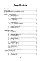
Table of Contents Box Contents...6 Optional Items...6 GA-P55A-UD3P/GA-P55A-UD3R Motherboard Layout 7 Block Diagram...8 Chapter 1 Hardware Installation 9 1-1 Installation Precautions 9 1-2 Product Specifications 10 1-3 Installing the CPU and CPU Cooler 13 1-3-1 Installing the CPU 13 1-3-2 Installing the CPU Cooler 15 1-4 Installing the Memory 16 1-4-1 Dual Channel Memory Configuration 16 1-4-2 Installing a Memory 17 1-5 Installing an Expansion Card 18 1-6 Back Panel...
Table of Contents Box Contents...6 Optional Items...6 GA-P55A-UD3P/GA-P55A-UD3R Motherboard Layout 7 Block Diagram...8 Chapter 1 Hardware Installation 9 1-1 Installation Precautions 9 1-2 Product Specifications 10 1-3 Installing the CPU and CPU Cooler 13 1-3-1 Installing the CPU 13 1-3-2 Installing the CPU Cooler 15 1-4 Installing the Memory 16 1-4-1 Dual Channel Memory Configuration 16 1-4-2 Installing a Memory 17 1-5 Installing an Expansion Card 18 1-6 Back Panel...
Manual
Page 8
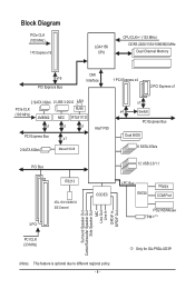
Block Diagram PCIe CLK (100 MHz) 1 PCI Express x16 LGA1156 CPU CPU CLK+/- (133 MHz) DDR3 2200/1333/1066/800 MHz Dual Channel Memory x16 PCI Express Bus DMI Interface 1 PCI Express x4 2 PCI Express x1 2 SATA ...) Surround Speaker Out Center/Subwoofer Speaker Out Side Speaker Out MIC Line Out Line In S/PDIF In S/PDIF Out PCI CLK (33 MHz) j Only for GA-P55A-UD3P. (Note) This feature is optional due to different regional policy. - 8 -
Block Diagram PCIe CLK (100 MHz) 1 PCI Express x16 LGA1156 CPU CPU CLK+/- (133 MHz) DDR3 2200/1333/1066/800 MHz Dual Channel Memory x16 PCI Express Bus DMI Interface 1 PCI Express x4 2 PCI Express x1 2 SATA ...) Surround Speaker Out Center/Subwoofer Speaker Out Side Speaker Out MIC Line Out Line In S/PDIF In S/PDIF Out PCI CLK (33 MHz) j Only for GA-P55A-UD3P. (Note) This feature is optional due to different regional policy. - 8 -
Manual
Page 9
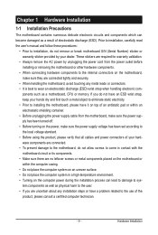
... other hardware components. • When connecting hardware components to the internal connectors on the computer power during the installation process can become damaged as a motherboard, CPU or memory. Hardware Installation Prior to installation, carefully read the user's manual and follow these procedures: • Prior to installation, do not remove or break...
... other hardware components. • When connecting hardware components to the internal connectors on the computer power during the installation process can become damaged as a motherboard, CPU or memory. Hardware Installation Prior to installation, carefully read the user's manual and follow these procedures: • Prior to installation, do not remove or break...
Manual
Page 10
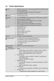
...™ i7 series processor/Intel® Core™ i5 series processor in the LGA1156 package (Go to GIGABYTE's website for the latest CPU support list.) L3 cache varies with CPU Chipset Intel® P55 Express Chipset Memory Audio 4 x 1.5V DDR3 DIMM sockets .../800 MHz memory modules Support for non-ECC memory modules Support for Extreme Memory Profile (XMP) memory modules (Go to GIGABYTE's website for the latest memory support list.) Realtek ALC889 codec High Definition Audio 2/4/5.1/7.1-channel Support for...
...™ i7 series processor/Intel® Core™ i5 series processor in the LGA1156 package (Go to GIGABYTE's website for the latest CPU support list.) L3 cache varies with CPU Chipset Intel® P55 Express Chipset Memory Audio 4 x 1.5V DDR3 DIMM sockets .../800 MHz memory modules Support for non-ECC memory modules Support for Extreme Memory Profile (XMP) memory modules (Go to GIGABYTE's website for the latest memory support list.) Realtek ALC889 codec High Definition Audio 2/4/5.1/7.1-channel Support for...

Manual
Page 11
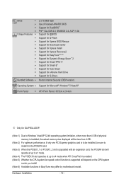
... Internal w 1 x 24-pin ATX main power connector Connectors w 1 x 8-pin ATX 12V power connector w 1 x floppy disk drive connector w 1 x IDE connector w 6 x SATA 3Gb/s connectors w 2 x SATA 6Gb/s connectors w 1 x CPU fan header w 2 x system fan headers w 1 x power fan header w 1 x front panel header w 1 x front panel audio header w 1 x CD In connector w 1 x S/PDIF In header w 1 x S/PDIF Out header w 2 x USB...
... Internal w 1 x 24-pin ATX main power connector Connectors w 1 x 8-pin ATX 12V power connector w 1 x floppy disk drive connector w 1 x IDE connector w 6 x SATA 3Gb/s connectors w 2 x SATA 6Gb/s connectors w 1 x CPU fan header w 2 x system fan headers w 1 x power fan header w 1 x front panel header w 1 x front panel audio header w 1 x CD In connector w 1 x S/PDIF In header w 1 x S/PDIF Out header w 2 x USB...
Manual
Page 12
...version) Operating System w Support for Microsoft® Windows® 7/Vista/XP Form Factor w ATX Form Factor; 30.5cm x 24.4cm j Only for GA-P55A-UD3P. (Note 1) Due to Windows Vista/XP 32-bit operating system limitation, when more than 4 GB of physical memory is installed, the actual memory ...to x1 mode. (Note 4) The PCIEX16 slot operates at up to x4 mode when ATI CrossFireX is enabled. (Note 5) Whether the CPU/system fan speed control function is supported will depend on the CPU/system cooler you install. (Note 6) Available functions in EasyTune may differ by motherboard model.
...version) Operating System w Support for Microsoft® Windows® 7/Vista/XP Form Factor w ATX Form Factor; 30.5cm x 24.4cm j Only for GA-P55A-UD3P. (Note 1) Due to Windows Vista/XP 32-bit operating system limitation, when more than 4 GB of physical memory is installed, the actual memory ...to x1 mode. (Note 4) The PCIEX16 slot operates at up to x4 mode when ATI CrossFireX is enabled. (Note 5) Whether the CPU/system fan speed control function is supported will depend on the CPU/system cooler you install. (Note 6) Available functions in EasyTune may differ by motherboard model.
Manual
Page 13
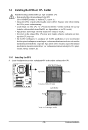
... the alignment keys on the motherboard CPU socket and the notches on the CPU - 13 - 1-3 Installing the CPU and CPU Cooler Read the following guidelines before you begin to install the CPU: • Make sure that the motherboard supports the CPU. (Go to GIGABYTE's website for the peripherals. age of the CPU. • Do not turn off the...
... the alignment keys on the motherboard CPU socket and the notches on the CPU - 13 - 1-3 Installing the CPU and CPU Cooler Read the following guidelines before you begin to install the CPU: • Make sure that the motherboard supports the CPU. (Go to GIGABYTE's website for the peripherals. age of the CPU. • Do not turn off the...
Manual
Page 14
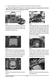
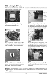
...hand to hold the socket lever and use your thumb to lift up the front edge (next to correctly install the CPU into its locked position. Step 1: Gently press the CPU socket lever handle down on the rear side of the socket cover and use the other to turn off the computer... cord from the socket with your thumb and index fingers. Step 2: Remove the CPU socket cover as well. Step 4: Once the CPU is not installed.) Step 3: Hold the CPU with the socket alignment keys) and gently insert the CPU into position. When replacing the load plate, make sure to lightly replace the load...
...hand to hold the socket lever and use your thumb to lift up the front edge (next to correctly install the CPU into its locked position. Step 1: Gently press the CPU socket lever handle down on the rear side of the socket cover and use the other to turn off the computer... cord from the socket with your thumb and index fingers. Step 2: Remove the CPU socket cover as well. Step 4: Once the CPU is not installed.) Step 3: Hold the CPU with the socket alignment keys) and gently insert the CPU into position. When replacing the load plate, make sure to lightly replace the load...
Manual
Page 15
... 5: After the installation, check the back of arrow is to remove the cooler, on the motherboard. 1-3-2 Installing the CPU Cooler Follow the steps below to correctly install the CPU cooler on the motherboard. (The following procedure uses Intel® boxed cooler as the picture above shows, the installation is... to install.) Step 3: Place the cooler atop the CPU, aligning the four push pins through the pin holes on the contrary, is complete. Direction of the Arrow Sign on the Male Push Pin ...
... 5: After the installation, check the back of arrow is to remove the cooler, on the motherboard. 1-3-2 Installing the CPU Cooler Follow the steps below to correctly install the CPU cooler on the motherboard. (The following procedure uses Intel® boxed cooler as the picture above shows, the installation is... to install.) Step 3: Place the cooler atop the CPU, aligning the four push pins through the pin holes on the contrary, is complete. Direction of the Arrow Sign on the Male Push Pin ...
Manual
Page 16
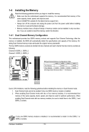
.../SS Four Modules DS/SS DS/SS DS/SS DS/SS (SS=Single-Sided, DS=Double-Sided, "- -"=No Memory) DDR3_2 DDR3_1 DDR3_4 DDR3_3 Due to CPU limitations, read the following : Channel 0: DDR3_1, DDR3_2 Channel 1: DDR3_3, DDR3_4 Dual Channel Memory Configurations Table DDR3_2 DDR3_1 DDR3_4 DDR3_3 Two Modules - - When enabling Dual Channel... direction. 1-4-1 Dual Channel Memory Configuration This motherboard provides four DDR3 memory sockets and supports Dual Channel Technology. The four DDR3 memory sockets are unable to GIGABYTE's website for optimum performance.
.../SS Four Modules DS/SS DS/SS DS/SS DS/SS (SS=Single-Sided, DS=Double-Sided, "- -"=No Memory) DDR3_2 DDR3_1 DDR3_4 DDR3_3 Due to CPU limitations, read the following : Channel 0: DDR3_1, DDR3_2 Channel 1: DDR3_3, DDR3_4 Dual Channel Memory Configurations Table DDR3_2 DDR3_1 DDR3_4 DDR3_3 Two Modules - - When enabling Dual Channel... direction. 1-4-1 Dual Channel Memory Configuration This motherboard provides four DDR3 memory sockets and supports Dual Channel Technology. The four DDR3 memory sockets are unable to GIGABYTE's website for optimum performance.
Manual
Page 22
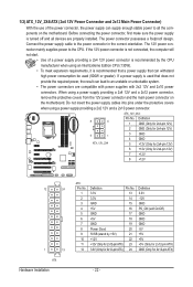
... No. 3.3V 13 3.3V 14 GND 15 +5V 16 GND 17 +5V 18 GND 19 Power Good 20 5VSB (stand by the CPU manufacturer when using an Intel Extreme Edition CPU (130W). • To meet expansion requirements, it is recommended that a power supply that can withstand high power consumption be used that... the 12V power connector and the main power connector on the motherboard. The power connector possesses a foolproof design. Connect the power supply cable to the CPU. If a power supply is turned off and all the components on the motherboard.
... No. 3.3V 13 3.3V 14 GND 15 +5V 16 GND 17 +5V 18 GND 19 Power Good 20 5VSB (stand by the CPU manufacturer when using an Intel Extreme Edition CPU (130W). • To meet expansion requirements, it is recommended that a power supply that can withstand high power consumption be used that... the 12V power connector and the main power connector on the motherboard. The power connector possesses a foolproof design. Connect the power supply cable to the CPU. If a power supply is turned off and all the components on the motherboard.

Manual
Page 23
... disk drive cable, please contact the local dealer. 33 1 34 2 - 23 - For optimum heat dissipation, it in damage to prevent your CPU and system from overheating. The pin 1 of the cable is the ground wire). 3/4/5) CPU_FAN/SYS_FAN1/SYS_FAN2/PWR_FAN (Fan Headers) The motherboard has a 4-pin...are not configuration jumper blocks. Definition 1 GND 2 +12V 3 Sense • Be sure to connect fan cables to the fan headers to the CPU or the system may result in the correct orientation (the black connector wire is typically designated by a stripe of the connector and the floppy disk...
... disk drive cable, please contact the local dealer. 33 1 34 2 - 23 - For optimum heat dissipation, it in damage to prevent your CPU and system from overheating. The pin 1 of the cable is the ground wire). 3/4/5) CPU_FAN/SYS_FAN1/SYS_FAN2/PWR_FAN (Fan Headers) The motherboard has a 4-pin...are not configuration jumper blocks. Definition 1 GND 2 +12V 3 Sense • Be sure to connect fan cables to the fan headers to the CPU or the system may result in the correct orientation (the black connector wire is typically designated by a stripe of the connector and the floppy disk...

Manual
Page 31
Refer to Chapter 4, "Dynamic Energy Saver™ 2," for more the number of lighted LEDs indicates the CPU loading. Hardware Installation The higher the CPU loading, the more details. - 31 - 20) PHASE LED The number of lighted LEDs. To enable the Phase LED display function, please first enable Dynamic Energy Saver™ 2.
Refer to Chapter 4, "Dynamic Energy Saver™ 2," for more the number of lighted LEDs indicates the CPU loading. Hardware Installation The higher the CPU loading, the more details. - 31 - 20) PHASE LED The number of lighted LEDs. To enable the Phase LED display function, please first enable Dynamic Energy Saver™ 2.
Manual
Page 35
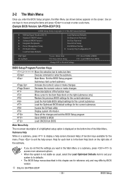
... a help screen. BIOS Setup Use arrow keys to move among the items and press to accept or enter a sub-menu. (Sample BIOS Version: GA-P55A-UD3P D12) CMOS Setup Utility-Copyright (C) 1984-2009 Award Software MB Intelligent Tweaker(M.I.T.) Standard CMOS Features Advanced BIOS Features ... & Exit Setup Exit Without Saving Security Chip Configuration j ESC: Quit F8: Q-Flash Select Item F10: Save & Exit Setup Change CPU's Clock & Voltage F11: Save CMOS to BIOS F12: Load CMOS from BIOS BIOS Setup Program Function Keys Move the selection bar to select an...
... a help screen. BIOS Setup Use arrow keys to move among the items and press to accept or enter a sub-menu. (Sample BIOS Version: GA-P55A-UD3P D12) CMOS Setup Utility-Copyright (C) 1984-2009 Award Software MB Intelligent Tweaker(M.I.T.) Standard CMOS Features Advanced BIOS Features ... & Exit Setup Exit Without Saving Security Chip Configuration j ESC: Quit F8: Q-Flash Select Item F10: Save & Exit Setup Change CPU's Clock & Voltage F11: Save CMOS to BIOS F12: Load CMOS from BIOS BIOS Setup Program Function Keys Move the selection bar to select an...
Manual
Page 36
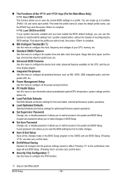
...information about autodetected system/CPU temperature, system voltage and fan speed, etc. Load Fail-Safe Defaults Fail-Safe defaults are factory settings for the most stable, minimal-performance system operations. Load Optimized Defaults Optimized defaults are factory settings for GA-P55A-UD3P. j Only...the system boot, etc. Advanced BIOS Features Use this menu to configure the device boot order, advanced features available on the CPU, and the primary display adapter. Integrated Peripherals Use this menu to configure all peripheral devices, such as IDE, SATA, ...
...information about autodetected system/CPU temperature, system voltage and fan speed, etc. Load Fail-Safe Defaults Fail-Safe defaults are factory settings for the most stable, minimal-performance system operations. Load Optimized Defaults Optimized defaults are factory settings for GA-P55A-UD3P. j Only...the system boot, etc. Advanced BIOS Features Use this menu to configure the device boot order, advanced features available on the CPU, and the primary display adapter. Integrated Peripherals Use this menu to configure all peripheral devices, such as IDE, SATA, ...
Manual
Page 37
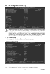
... Frequency Settings CMOS Setup Utility-Copyright (C) 1984-2009 Award Software Advanced Frequency Settings CPU Clock Ratio CPU Frequency } Advanced CPU Core Features QPI Clock Ratio QPI Link Speed Uncore Clock Ratio Uncore Frequency >>>>> Standard... (X.M.P.) (Note) System Memory Multiplier (SPD) Memory Frequency (Mhz) 1333 PCI Express Frequency (Mhz) C.I.A.2 >>>>> Advanced Clock Control CPU Clock Drive PCI Express Clock Drive CPU Clock Skew [16X] 2.13GHz (133x16) [Press Enter] [Auto] 4.26GHz 15x 2000MHz [Disabled] 133 [Disabled] [Auto] ...
... Frequency Settings CMOS Setup Utility-Copyright (C) 1984-2009 Award Software Advanced Frequency Settings CPU Clock Ratio CPU Frequency } Advanced CPU Core Features QPI Clock Ratio QPI Link Speed Uncore Clock Ratio Uncore Frequency >>>>> Standard... (X.M.P.) (Note) System Memory Multiplier (SPD) Memory Frequency (Mhz) 1333 PCI Express Frequency (Mhz) C.I.A.2 >>>>> Advanced Clock Control CPU Clock Drive PCI Express Clock Drive CPU Clock Skew [16X] 2.13GHz (133x16) [Press Enter] [Auto] 4.26GHz 15x 2000MHz [Disabled] 133 [Disabled] [Auto] ...
Manual
Page 38
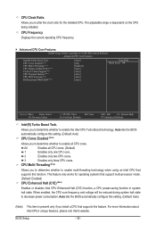
...this setting. (Default: Auto) (Note) This item is dependent on the CPU being installed. CPU Cores Enabled (Note) CPU Multi-Threading (Note) CPU Enhanced Halt (C1E) (Note) C3/C6/C7 State Support (Note) CPU Thermal Monitor (Note) CPU EIST Function (Note) Bi-Directional PROCHOT (Note) [Auto] [All] [Enabled... configure this setting. (Default: Auto) CPU Cores Enabled (Note) Allows you to determine whether to enable all CPU cores. (Default) 1 Enables only one CPU core. 2 Enables only two CPU cores. 3 Enables only three CPU cores. CPU Clock Ratio Allows you to alter the ...
...this setting. (Default: Auto) (Note) This item is dependent on the CPU being installed. CPU Cores Enabled (Note) CPU Multi-Threading (Note) CPU Enhanced Halt (C1E) (Note) C3/C6/C7 State Support (Note) CPU Thermal Monitor (Note) CPU EIST Function (Note) Bi-Directional PROCHOT (Note) [Auto] [All] [Enabled... configure this setting. (Default: Auto) CPU Cores Enabled (Note) Allows you to determine whether to enable all CPU cores. (Default) 1 Enables only one CPU core. 2 Enables only two CPU cores. 3 Enables only three CPU cores. CPU Clock Ratio Allows you to alter the ...

Manual
Page 39
...by the Uncore Clock Ratio value. >>>>> Standard Clock Control Base Clock(BCLK) Control Enables or disables the control of CPU base clock. Enabled will be reduced when the CPU is occurring, PROCHOT signals will be reduced during system halt state to decrease power consumption. Auto lets the BIOS ...clear the CMOS values to reset the board to default values. (Default: Disabled) (Note) This item is present only if you install a CPU that an overheating is overheated. The C3/C6/C7 state is occurring to decrease average power consumption and heat production. Only allows the...
...by the Uncore Clock Ratio value. >>>>> Standard Clock Control Base Clock(BCLK) Control Enables or disables the control of CPU base clock. Enabled will be reduced when the CPU is occurring, PROCHOT signals will be reduced during system halt state to decrease power consumption. Auto lets the BIOS ...clear the CMOS values to reset the board to default values. (Default: Disabled) (Note) This item is present only if you install a CPU that an overheating is overheated. The C3/C6/C7 state is occurring to decrease average power consumption and heat production. Only allows the...
Manual
Page 40
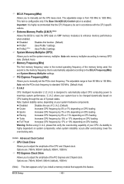
... clock. Disabled Disables the use of C.I.A.2. (Default) Cruise Increases CPU frequency by 7% or 9% depending on CPU loading. As stability is the memory frequency that the CPU frequency be changed dynamically based on CPU loading through the use of 5 preset states. PCI Express Clock ... is enabled. Options are : 700mV, 800mV (default), 900mV, 1000mV. System Memory Multiplier (SPD) Allows you to manually set the CPU base clock. BCLK Frequency(Mhz) Allows you to set the system memory multiplier. Note: System stability varies, depending on XMP memory module...
... clock. Disabled Disables the use of C.I.A.2. (Default) Cruise Increases CPU frequency by 7% or 9% depending on CPU loading. As stability is the memory frequency that the CPU frequency be changed dynamically based on CPU loading through the use of 5 preset states. PCI Express Clock ... is enabled. Options are : 700mV, 800mV (default), 900mV, 1000mV. System Memory Multiplier (SPD) Allows you to manually set the CPU base clock. BCLK Frequency(Mhz) Allows you to set the system memory multiplier. Note: System stability varies, depending on XMP memory module...

Manual
Page 41
...at its good performance level. (Default) Extreme Lets the system operate at its basic performance level. System Memory Multiplier (SPD) Allows you to set the CPU clock prior to the Chipset clock. Options are : Auto (default), Quick, Expert. (Note) This item appears only if you install a memory module... and Rank Interleaving items to be configurable. Performance Enhance Allows the system to operate at its best performance level. BIOS Setup CPU Clock Skew Allows you to set the system memory multiplier. Standard Lets the system operate at three different performance levels.
...at its good performance level. (Default) Extreme Lets the system operate at its basic performance level. System Memory Multiplier (SPD) Allows you to set the CPU clock prior to the Chipset clock. Options are : Auto (default), Quick, Expert. (Note) This item appears only if you install a memory module... and Rank Interleaving items to be configurable. Performance Enhance Allows the system to operate at its best performance level. BIOS Setup CPU Clock Skew Allows you to set the system memory multiplier. Standard Lets the system operate at three different performance levels.


