
Manual
Page 5
... 9128 SATA Controller 89 5-1-3 Making a SATA RAID/AHCI Driver Diskette 94 5-1-4 Installing the SATA RAID/AHCI Driver and Operating System 95 5-2 Configuring Audio Input and Output 104 5-2-1 Configuring 2/4/5.1/7.1-Channel Audio 104 5-2-2 Configuring S/PDIF In/Out 106 5-2-3 Configuring Microphone Recording 108 5-2-4 Using the Sound Recorder 110 5-3 Troubleshooting 111 5-3-1 Frequently Asked Questions 111 5-3-2 Troubleshooting...
... 9128 SATA Controller 89 5-1-3 Making a SATA RAID/AHCI Driver Diskette 94 5-1-4 Installing the SATA RAID/AHCI Driver and Operating System 95 5-2 Configuring Audio Input and Output 104 5-2-1 Configuring 2/4/5.1/7.1-Channel Audio 104 5-2-2 Configuring S/PDIF In/Out 106 5-2-3 Configuring Microphone Recording 108 5-2-4 Using the Sound Recorder 110 5-3 Troubleshooting 111 5-3-1 Frequently Asked Questions 111 5-3-2 Troubleshooting...
Manual
Page 7
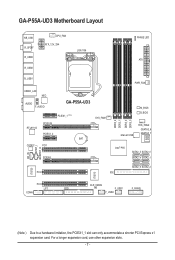
... Layout KB_USB R_SPDIF R_USB3 R_USB2 CPU_FAN ATX_12V_2X4 LGA1156 PHASE LED ATX R_USB1 USB30_LAN NEC AUDIO F_AUDIO GA-P55A-UD3 PCIEX1_1 (Note) RTL8111D PCIEX16 PCIEX1_2 BAT CODEC PCI1 SYS_FAN1 CD_IN SPDIF_I SPDIF_O PCIEX4 DDR3_2 DDR3_1 DDR3_4 DDR3_3 PWR_FAN M_BIOS B_BIOS Marvell 9128 SYS_FAN2 GSATA3_6 GSATA3_7 ...
... Layout KB_USB R_SPDIF R_USB3 R_USB2 CPU_FAN ATX_12V_2X4 LGA1156 PHASE LED ATX R_USB1 USB30_LAN NEC AUDIO F_AUDIO GA-P55A-UD3 PCIEX1_1 (Note) RTL8111D PCIEX16 PCIEX1_2 BAT CODEC PCI1 SYS_FAN1 CD_IN SPDIF_I SPDIF_O PCIEX4 DDR3_2 DDR3_1 DDR3_4 DDR3_3 PWR_FAN M_BIOS B_BIOS Marvell 9128 SYS_FAN2 GSATA3_6 GSATA3_7 ...

Manual
Page 10
...174; Core™ i5 series processor in the LGA1156 package (Go to GIGABYTE's website for the latest CPU support list.) L3 cache varies with CPU Chipset Intel® P55 Express Chipset Memory Audio 4 x 1.5V DDR3 DIMM sockets supporting up to 16 GB...for non-ECC memory modules Support for Extreme Memory Profile (XMP) memory modules (Go to GIGABYTE's website for the latest memory support list.) Realtek ALC888 codec High Definition Audio 2/4/5.1/7.1-channel Support for S/PDIF In/Out Support for CD In LAN ...
...174; Core™ i5 series processor in the LGA1156 package (Go to GIGABYTE's website for the latest CPU support list.) L3 cache varies with CPU Chipset Intel® P55 Express Chipset Memory Audio 4 x 1.5V DDR3 DIMM sockets supporting up to 16 GB...for non-ECC memory modules Support for Extreme Memory Profile (XMP) memory modules (Go to GIGABYTE's website for the latest memory support list.) Realtek ALC888 codec High Definition Audio 2/4/5.1/7.1-channel Support for S/PDIF In/Out Support for CD In LAN ...

Manual
Page 11
...SATA 6Gb/s connectors w 1 x CPU fan header w 2 x system fan headers w 1 x power fan header w 1 x front panel header w 1 x front panel audio header w 1 x CD In connector w 1 x S/PDIF In header w 1 x S/PDIF Out header w 2 x USB 2.0/1.1 headers w 1 x serial port header w...PDIF Out connector w 8 x USB 2.0/1.1 ports w 2 x USB 3.0 ports w 1 x RJ-45 port w 6 x audio jacks (Center/Subwoofer Speaker Out/Rear Speaker Out/ Side Speaker Out/Line In/Line Out/Microphone) I/O Controller w iTE IT8720 chip ...
...SATA 6Gb/s connectors w 1 x CPU fan header w 2 x system fan headers w 1 x power fan header w 1 x front panel header w 1 x front panel audio header w 1 x CD In connector w 1 x S/PDIF In header w 1 x S/PDIF Out header w 2 x USB 2.0/1.1 headers w 1 x serial port header w...PDIF Out connector w 8 x USB 2.0/1.1 ports w 2 x USB 3.0 ports w 1 x RJ-45 port w 6 x audio jacks (Center/Subwoofer Speaker Out/Rear Speaker Out/ Side Speaker Out/Line In/Line Out/Microphone) I/O Controller w iTE IT8720 chip ...

Manual
Page 19
...flash drive and etc. • When removing the cable connected to a back panel connector, first remove the cable from your audio system provides a coaxial digital audio in connector. PS/2 Keyboard/Mouse Port Use this feature, ensure that your device and then remove it from the motherboard. •...The Gigabit Ethernet LAN port provides Internet connection at up to the USB 2.0/1.1 specification. Optical S/PDIF Out Connector This connector provides digital audio out to prevent an electrical short inside the cable connector. - 19 - The following describes the states of the LAN port LEDs....
...flash drive and etc. • When removing the cable connected to a back panel connector, first remove the cable from your audio system provides a coaxial digital audio in connector. PS/2 Keyboard/Mouse Port Use this feature, ensure that your device and then remove it from the motherboard. •...The Gigabit Ethernet LAN port provides Internet connection at up to the USB 2.0/1.1 specification. Optical S/PDIF Out Connector This connector provides digital audio out to prevent an electrical short inside the cable connector. - 19 - The following describes the states of the LAN port LEDs....

Manual
Page 20
...Jack (Blue) The default line in Chapter 5, "Configuring 2/4/5.1/7.1-Channel Audio." Hardware Installation - 20 - Use this audio jack to connect rear speakers in a 4/5.1/7.1-channel audio configuration. Refer to the instructions on setting up a 2/4/5.1/7.1-channel audio configuration in jack. Line Out Jack (Green) The default line... out jack. Mic In Jack (Pink) The default Mic in a 7.1-channel audio configuration. Side Speaker Out Jack (Gray) Use this audio jack to connect side speakers in jack. Only microphones still MUST be connected to this jack. Center...
...Jack (Blue) The default line in Chapter 5, "Configuring 2/4/5.1/7.1-Channel Audio." Hardware Installation - 20 - Use this audio jack to connect rear speakers in a 4/5.1/7.1-channel audio configuration. Refer to the instructions on setting up a 2/4/5.1/7.1-channel audio configuration in jack. Line Out Jack (Green) The default line... out jack. Mic In Jack (Pink) The default Mic in a 7.1-channel audio configuration. Side Speaker Out Jack (Gray) Use this audio jack to connect side speakers in jack. Only microphones still MUST be connected to this jack. Center...

Manual
Page 27
Make sure the wire assignments of the module connector match the pin assignments of a single plug. For HD Front Panel Audio: For AC'97 Front Panel Audio: Pin No. Definition 1 2 1 MIC2_L 1 MIC 2 GND 2 GND 9 10 3 MIC2_R 3 MIC Power 4 -ACZ_DET 4 NC 5 LINE2_R 5 Line Out (R) 6 GND 6 NC 7 FAUDIO_JD 7 NC...instead of the motherboard header. 12) F_AUDIO (Front Panel Audio Header) The front panel audio header supports Intel High Definition audio (HD) and AC'97 audio. If your chassis provides an AC'97 front panel audio module, refer to the instructions on how to activate AC...
Make sure the wire assignments of the module connector match the pin assignments of a single plug. For HD Front Panel Audio: For AC'97 Front Panel Audio: Pin No. Definition 1 2 1 MIC2_L 1 MIC 2 GND 2 GND 9 10 3 MIC2_R 3 MIC Power 4 -ACZ_DET 4 NC 5 LINE2_R 5 Line Out (R) 6 GND 6 NC 7 FAUDIO_JD 7 NC...instead of the motherboard header. 12) F_AUDIO (Front Panel Audio Header) The front panel audio header supports Intel High Definition audio (HD) and AC'97 audio. If your chassis provides an AC'97 front panel audio module, refer to the instructions on how to activate AC...

Manual
Page 28
...cards like graphics cards and sound cards. Pin No. For example, some graphics cards may require you to use a S/PDIF digital audio cable for digital audio output from your motherboard to your expansion card. 14) SPDIF_I (S/PDIF In Header) This header supports digital S/PDIF In and can... connect to the graphics card and have digital audio output from the HDMI display at the same time. Definition 1 SPDIFO 2 GND 1 Hardware Installation - 28 - Definition 1 Power 2 SPDIFI 3 GND 1 15) ...
...cards like graphics cards and sound cards. Pin No. For example, some graphics cards may require you to use a S/PDIF digital audio cable for digital audio output from your motherboard to your expansion card. 14) SPDIF_I (S/PDIF In Header) This header supports digital S/PDIF In and can... connect to the graphics card and have digital audio output from the HDMI display at the same time. Definition 1 SPDIFO 2 GND 1 Hardware Installation - 28 - Definition 1 Power 2 SPDIFI 3 GND 1 15) ...

Manual
Page 36
... on the CPU, and the primary display adapter. Integrated Peripherals Use this menu to configure all peripheral devices, such as IDE, SATA, USB, integrated audio, and integrated LAN, etc. Power Management Setup Use this menu to configure all the power-saving functions. PC Health Status Use this menu...
... on the CPU, and the primary display adapter. Integrated Peripherals Use this menu to configure all peripheral devices, such as IDE, SATA, USB, integrated audio, and integrated LAN, etc. Power Management Setup Use this menu to configure all the power-saving functions. PC Health Status Use this menu...
Manual
Page 51
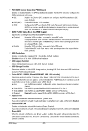
... Marvell 9128 and NEC USB 3.0 controllers to AHCI mode. Azalia Codec Enables or disables the onboard audio function. (Default: Auto) If you wish to install a 3rd party add-in audio card instead of using the onboard audio, set this option to Disabled if you wish to Disabled. Onboard H/W LAN Enables or disables the...
... Marvell 9128 and NEC USB 3.0 controllers to AHCI mode. Azalia Codec Enables or disables the onboard audio function. (Default: Auto) If you wish to install a 3rd party add-in audio card instead of using the onboard audio, set this option to Disabled if you wish to Disabled. Onboard H/W LAN Enables or disables the...

Manual
Page 104
...make a telephone call over the Internet, and etc. The integrated HD (High Definition) audio provides jack retasking capability that allows the user to the right shows the default audio jack assignments. The picture to change Center/Subwoofer Speaker Out Rear Speaker Out Side Speaker ...Out Line In Front Speaker Out Mic In the function for microphone functionality. • Audio signals will appear in a 4-channel audio configuration, if a Rear speaker is plugged into the default Center/Sub- Configuring Speakers (The following for multi-channel ...
...make a telephone call over the Internet, and etc. The integrated HD (High Definition) audio provides jack retasking capability that allows the user to the right shows the default audio jack assignments. The picture to change Center/Subwoofer Speaker Out Rear Speaker Out Side Speaker ...Out Line In Front Speaker Out Mic In the function for microphone functionality. • Audio signals will appear in a 4-channel audio configuration, if a Rear speaker is plugged into the default Center/Sub- Configuring Speakers (The following for multi-channel ...

Manual
Page 105
... OK. Then the speaker setup is dialog box appears. The The current connected device is completed. Configuring Sound Effect You may configure an audio environment on the Sound Effects tab. Click OK to open the Device advanced settings dialog box. C. Muting the Back Panel...top right corner on the Speaker Configuration tab to complete. B. Activating an AC'97 Front Panel Audio Module If your chassis provides an AC'97 front panel audio module, to an audio jack. Step 2: Connect an audio device to activate the AC'97 functionality, click the tool icon on the Speaker Configuration tab....
... OK. Then the speaker setup is dialog box appears. The The current connected device is completed. Configuring Sound Effect You may configure an audio environment on the Sound Effects tab. Click OK to open the Device advanced settings dialog box. C. Muting the Back Panel...top right corner on the Speaker Configuration tab to complete. B. Activating an AC'97 Front Panel Audio Module If your chassis provides an AC'97 front panel audio module, to an audio jack. Step 2: Connect an audio device to activate the AC'97 functionality, click the tool icon on the Speaker Configuration tab....

Manual
Page 106
.... Click OK to select the default format. S/PDIF In The S/PDIF In cable (optional) allows you to input digital audio signals to the SPDIF_I header on your motherboard. Installing the S/PDIF In Cable: Step 1: First, attach the connector at the end of the S/PDIF In ...
.... Click OK to select the default format. S/PDIF In The S/PDIF In cable (optional) allows you to input digital audio signals to the SPDIF_I header on your motherboard. Installing the S/PDIF In Cable: Step 1: First, attach the connector at the end of the S/PDIF In ...

Manual
Page 107
Connecting a S/PDIF Out Cable: S/PDIF Coaxial Cable S/PDIF Optical Cable Connect a S/PDIF coaxial cable or a S/PDIF optical cable (either one) to complete. - 107 - Click OK to an external decoder for decoding to get the best audio quality. 1. B. S/PDIF Out The S/PDIF Out jacks can transmit audio signals to an external decoder for transmitting the S/PDIF digital audio signals. 2. Configuring S/PDIF Out: On the Digital Output screen, click the Default Format tab and then select the sample rate and bit depth. Appendix
Connecting a S/PDIF Out Cable: S/PDIF Coaxial Cable S/PDIF Optical Cable Connect a S/PDIF coaxial cable or a S/PDIF optical cable (either one) to complete. - 107 - Click OK to an external decoder for decoding to get the best audio quality. 1. B. S/PDIF Out The S/PDIF Out jacks can transmit audio signals to an external decoder for transmitting the S/PDIF digital audio signals. 2. Configuring S/PDIF Out: On the Digital Output screen, click the Default Format tab and then select the sample rate and bit depth. Appendix

Manual
Page 108
... being recorded during the recording process, do not mute the playback volume. Then configure the jack for microphone functionality. Step 3: Go to access the HD Audio Manager. 5-2-3 Configuring Microphone Recording Step 1: After installing the audio driver, the HD Audio Manager icon will appear in jack (pink) on the front panel.
... being recorded during the recording process, do not mute the playback volume. Then configure the jack for microphone functionality. Step 3: Go to access the HD Audio Manager. 5-2-3 Configuring Microphone Recording Step 1: After installing the audio driver, the HD Audio Manager icon will appear in jack (pink) on the front panel.

Manual
Page 109
..., click Start, point to All Programs, point to Accessories, and then click Sound Recorder to begin the sound recording. * Enabling Stereo Mix If the HD Audio Manager does not display the recording device you want to the steps below.
..., click Start, point to All Programs, point to Accessories, and then click Sound Recorder to begin the sound recording. * Enabling Stereo Mix If the HD Audio Manager does not display the recording device you want to the steps below.

Manual
Page 110
... to the computer. 2. Make sure you can play your recording in a digital media player program that supports your audio file format. Appendix - 110 - To stop recording audio, click the Stop Recording button . Step 4: Now you have connected the sound input device (e.g. Playing the Recorded ...Sound You can access the HD Audio Manager to configure Stereo Mix and use Sound Recorder to record the sound. 5-2-4 Using the Sound Recorder A. B. Recording Sound 1. microphone) to save the recorded audio file upon completion. Then set it as the default ...
... to the computer. 2. Make sure you can play your recording in a digital media player program that supports your audio file format. Appendix - 110 - To stop recording audio, click the Stop Recording button . Step 4: Now you have connected the sound input device (e.g. Playing the Recorded ...Sound You can access the HD Audio Manager to configure Stereo Mix and use Sound Recorder to record the sound. 5-2-4 Using the Sound Recorder A. B. Recording Sound 1. microphone) to save the recorded audio file upon completion. Then set it as the default ...

Manual
Page 111
... still on Microsoft UAA Bus Driver for hardware changes. You can temporarily remove the battery from GIGABYTE's website to install. If not, try a speaker with an internal amplifier. Step 2: Check if Audio Device on High Definition Audio Bus or Unknown device is still on. Then install the onboard HD... the CMOS values (before doing this, please turn off the computer and unplug the power cord). Step 4: In Device Manager, right-click on GIGABYTE's website. When the Add New Hardware Wizard appears, click Cancel. For more FAQs for your board doesn't have a CMOS_SW button, press this ...
... still on Microsoft UAA Bus Driver for hardware changes. You can temporarily remove the battery from GIGABYTE's website to install. If not, try a speaker with an internal amplifier. Step 2: Check if Audio Device on High Definition Audio Bus or Unknown device is still on. Then install the onboard HD... the CMOS values (before doing this, please turn off the computer and unplug the power cord). Step 4: In Device Manager, right-click on GIGABYTE's website. When the Add New Hardware Wizard appears, click Cancel. For more FAQs for your board doesn't have a CMOS_SW button, press this ...


