
Manual
Page 1
... integrated in the array. ) 1. Setting Up a RAID-Ready System Step 1: Configure the system BIOS Enter the system BIOS Setup program, set up all motherboard drivers, including the X.H.D utility. Using GIGABYTE eXtreme Hard Drive (X.H.D) Instructions:(Note 2) Before launching X.H.D, make sure the new drive is recommended that... RAID array depending on your hard drive read/write performance without the need for RAID 0. eXtreme Hard Drive (X.H.D) With GIGABYTE eXtreme Hard Drive (X.H.D)(Note 1), users can quickly configure a RAIDready system for the Intel SATA controllers.
... integrated in the array. ) 1. Setting Up a RAID-Ready System Step 1: Configure the system BIOS Enter the system BIOS Setup program, set up all motherboard drivers, including the X.H.D utility. Using GIGABYTE eXtreme Hard Drive (X.H.D) Instructions:(Note 2) Before launching X.H.D, make sure the new drive is recommended that... RAID array depending on your hard drive read/write performance without the need for RAID 0. eXtreme Hard Drive (X.H.D) With GIGABYTE eXtreme Hard Drive (X.H.D)(Note 1), users can quickly configure a RAIDready system for the Intel SATA controllers.

Manual
Page 2
Configuring the System BIOS 3 2. Installing the Smart TPM Utility 4 3. Advanced Mode...8 4. Configuring the Smart TPM Utility 18 4.1. Other Bluetooth Settings 21 4.4. Initializing the TPM chip 5 3.1. Installing the Infineon TPM Driver 4 2.2. Initializing the TPM Chip with the Smart TPM Utility 5 3.2. Other Features...21 - 2 - Creating a Bluetooth Cell Phone Key 19 4.3. Table of Contents TPM Configuration Procedure 3 1. Installing the Infineon TPM Driver and the Smart TPM Utility 4 2.1. Creating a USB Key 18 4.2.
Configuring the System BIOS 3 2. Installing the Smart TPM Utility 4 3. Advanced Mode...8 4. Configuring the Smart TPM Utility 18 4.1. Other Bluetooth Settings 21 4.4. Initializing the TPM chip 5 3.1. Installing the Infineon TPM Driver 4 2.2. Initializing the TPM Chip with the Smart TPM Utility 5 3.2. Other Features...21 - 2 - Creating a Bluetooth Cell Phone Key 19 4.3. Table of Contents TPM Configuration Procedure 3 1. Installing the Infineon TPM Driver and the Smart TPM Utility 4 2.1. Creating a USB Key 18 4.2.

Manual
Page 3
...completing the settings, press to back up the encrypted files first. Initializing the TPM chip 4. Configuring the System BIOS To use the Clear Security Chip setting (press + in the BIOS main menu to display this setting) to activate the TPM chip. It's recommended that you use the TPM ... the following screen will become inaccessible after the TPM chip is cleared. TPM Configuration Procedure To enable the TPM, follow the steps below in the BIOS Setup program. - 3 - Go to Enabled/Activate. To activate the TPM chip, set the User Password in sequence: 1. Be sure to...
...completing the settings, press to back up the encrypted files first. Initializing the TPM chip 4. Configuring the System BIOS To use the Clear Security Chip setting (press + in the BIOS main menu to display this setting) to activate the TPM chip. It's recommended that you use the TPM ... the following screen will become inaccessible after the TPM chip is cleared. TPM Configuration Procedure To enable the TPM, follow the steps below in the BIOS Setup program. - 3 - Go to Enabled/Activate. To activate the TPM chip, set the User Password in sequence: 1. Be sure to...

Manual
Page 5
... the PSD drive letter, drive label, size, and a local drive on which indicates that is automatically provided. Initializing the TPM chip After configuring the system BIOS and installing the driver software, the Infineon Security Platform icon , which your PSD will be saved. To make further settings, please select "Advanced mode." •...
... the PSD drive letter, drive label, size, and a local drive on which indicates that is automatically provided. Initializing the TPM chip After configuring the system BIOS and installing the driver software, the Infineon Security Platform icon , which your PSD will be saved. To make further settings, please select "Advanced mode." •...

Manual
Page 6
... the Security Platform in the Confirm User Password box again to meet your Personal Secure Drive and enter the Personal Secure Drive size in the BIOS Setup program. • This password incorporates the functionalities of the "Owner Password," "User Password," "Emergency Recovery Token Password," and "Password Reset Token Password" of the...
... the Security Platform in the Confirm User Password box again to meet your Personal Secure Drive and enter the Personal Secure Drive size in the BIOS Setup program. • This password incorporates the functionalities of the "Owner Password," "User Password," "Emergency Recovery Token Password," and "Password Reset Token Password" of the...

Manual
Page 7
... one user stores their encrypted TPM User Passwords in Passkey which will overwrite the former. 2. Selecting the Enable Backup to BIOS check box will appear. Enter a passkey (8~16 digits recommended) in the BIOS, the latter will be used for the Bluetooth enabled cell phone(s). Upon completing the steps above, click OK to... the Smart TPM user key(s). - 7 - Create a USB key: Select the Use USB storage check box and click Refresh to that you plug in the system BIOS. If more than one USB flash drive at the same time.
... one user stores their encrypted TPM User Passwords in Passkey which will overwrite the former. 2. Selecting the Enable Backup to BIOS check box will appear. Enter a passkey (8~16 digits recommended) in the BIOS, the latter will be used for the Bluetooth enabled cell phone(s). Upon completing the steps above, click OK to... the Smart TPM user key(s). - 7 - Create a USB key: Select the Use USB storage check box and click Refresh to that you plug in the system BIOS. If more than one USB flash drive at the same time.

Manual
Page 18
... the files encrypted via the TPM unable to display the menu as a result of the password(s) or the key(s) will overwrite the former. - 18 - GIGABYTE is not liable for loss of encrypted data as shown below. Step 2: Click Configure Smart TPM Devices to store them up the TPM User Password... 1: After initializing the TPM chip and setting up . Loss of hardware damage. 4.1. Users can create more than one user uses the "Enable Bacup to BIOS" function to store their PSD data by simply connecting to the Bluetooth cell phone or plugging in the notification area to be sure to launch...
... the files encrypted via the TPM unable to display the menu as a result of the password(s) or the key(s) will overwrite the former. - 18 - GIGABYTE is not liable for loss of encrypted data as shown below. Step 2: Click Configure Smart TPM Devices to store them up the TPM User Password... 1: After initializing the TPM chip and setting up . Loss of hardware damage. 4.1. Users can create more than one user uses the "Enable Bacup to BIOS" function to store their PSD data by simply connecting to the Bluetooth cell phone or plugging in the notification area to be sure to launch...

Manual
Page 19
... Configure BT Devices and then select the Bluetooth cell phone that you set earlier and click OK to access/close your PSD by plugging in BIOS Setup and then set "Security Chip" to confirm, click Yes. You are able to complete creating the USB key. To cancel a USB key: To cancel...
... Configure BT Devices and then select the Bluetooth cell phone that you set earlier and click OK to access/close your PSD by plugging in BIOS Setup and then set "Security Chip" to confirm, click Yes. You are able to complete creating the USB key. To cancel a USB key: To cancel...

Manual
Page 3
... may be made by copyright laws and is the property of the motherboard is 1.0. For product-related information, check on our website at: http://www.gigabyte.com.tw Identifying Your Motherboard Revision The revision number on our website. All rights reserved. Changes to their respective owners. For detailed product information, carefully... read or download the information on/from the Support&Downloads\Motherboard\Technology Guide page on your motherboard revision before updating motherboard BIOS, drivers, or when looking for technical information.
... may be made by copyright laws and is the property of the motherboard is 1.0. For product-related information, check on our website at: http://www.gigabyte.com.tw Identifying Your Motherboard Revision The revision number on our website. All rights reserved. Changes to their respective owners. For detailed product information, carefully... read or download the information on/from the Support&Downloads\Motherboard\Technology Guide page on your motherboard revision before updating motherboard BIOS, drivers, or when looking for technical information.

Manual
Page 4
Table of Contents Box Contents...6 Optional Items...6 GA-P55-UD4P/GA-P55-UD4 Motherboard Layout 7 Block Diagram...8 Chapter 1 Hardware Installation 9 1-1 Installation Precautions 9 1-2 Product Specifications 10 1-3 Installing the CPU and CPU Cooler ...8482;/NVIDIA SLI Configuration 19 1-7 Back Panel Connectors 20 1-8 Internal Connectors 22 Chapter 2 BIOS Setup 35 2-1 Startup Screen 36 2-2 The Main Menu 37 2-3 MB Intelligent Tweaker(M.I.T 39 2-4 Standard CMOS Features 49 2-5 Advanced BIOS Features 51 2-6 Integrated Peripherals 53 2-7 Power Management Setup 57 2-8 PC Health Status ...
Table of Contents Box Contents...6 Optional Items...6 GA-P55-UD4P/GA-P55-UD4 Motherboard Layout 7 Block Diagram...8 Chapter 1 Hardware Installation 9 1-1 Installation Precautions 9 1-2 Product Specifications 10 1-3 Installing the CPU and CPU Cooler ...8482;/NVIDIA SLI Configuration 19 1-7 Back Panel Connectors 20 1-8 Internal Connectors 22 Chapter 2 BIOS Setup 35 2-1 Startup Screen 36 2-2 The Main Menu 37 2-3 MB Intelligent Tweaker(M.I.T 39 2-4 Standard CMOS Features 49 2-5 Advanced BIOS Features 51 2-6 Integrated Peripherals 53 2-7 Power Management Setup 57 2-8 PC Health Status ...
Manual
Page 5
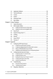
...Flash Utility 72 4-2-2 Updating the BIOS with the @BIOS Utility 75 4-3 EasyTune 6...76 4-4 Dynamic Energy Saver™ 2 77 4-5 Q-Share...79 4-6 Smart 6™ ...80 4-7 Smart TPM j 83 4-8 Teaming j 84 Chapter 5 Appendix...85 5-1 Configuring SATA Hard Drive(s 85 5-1-1 Configuring Intel P55 SATA Controllers 85 5-1-2 Configuring JMB362/GIGABYTE SATA2 SATA Controller 93 5-1-3 Making... 116 5-2-5 Using the Sound Recorder 118 5-3 Troubleshooting 119 5-3-1 Frequently Asked Questions 119 5-3-2 Troubleshooting Procedure 120 5-4 Regulatory Statements 122 j Only for GA-P55-UD4P. - 5 -
...Flash Utility 72 4-2-2 Updating the BIOS with the @BIOS Utility 75 4-3 EasyTune 6...76 4-4 Dynamic Energy Saver™ 2 77 4-5 Q-Share...79 4-6 Smart 6™ ...80 4-7 Smart TPM j 83 4-8 Teaming j 84 Chapter 5 Appendix...85 5-1 Configuring SATA Hard Drive(s 85 5-1-1 Configuring Intel P55 SATA Controllers 85 5-1-2 Configuring JMB362/GIGABYTE SATA2 SATA Controller 93 5-1-3 Making... 116 5-2-5 Using the Sound Recorder 118 5-3 Troubleshooting 119 5-3-1 Frequently Asked Questions 119 5-3-2 Troubleshooting Procedure 120 5-4 Regulatory Statements 122 j Only for GA-P55-UD4P. - 5 -

Manual
Page 8
... PCI Express Bus PCIe CLK x1 x1 x1 (100 MHz) x1 3 PCI Express x1 2 SATA 3Gb/s ATA-133/100/66/33 IDE Channel PCI Bus GIGABYTE SATA2 TSB43AB23 3 IEEE 1394a LGA1156 CPU CPU CLK+/- (133 MHz) DDR3 2200/1333/1066/800 MHz Dual Channel Memory DMI Interface Intel®...; P55 PCI Express Bus x1 2 SATA 3Gb/s JMB362 Dual BIOS 6 SATA 3Gb/s 14 USB Ports CODEC LPC Bus IT8720 Floppy COM Port PS/2 KB/Mouse TPM j Surround Speaker Out Center/Subwoofer Speaker Out Side Speaker Out MIC Line Out Line In S/PDIF In S/PDIF Out 2 PCI PCI CLK (33 MHz) j Only for GA-P55-UD4P...
... PCI Express Bus PCIe CLK x1 x1 x1 (100 MHz) x1 3 PCI Express x1 2 SATA 3Gb/s ATA-133/100/66/33 IDE Channel PCI Bus GIGABYTE SATA2 TSB43AB23 3 IEEE 1394a LGA1156 CPU CPU CLK+/- (133 MHz) DDR3 2200/1333/1066/800 MHz Dual Channel Memory DMI Interface Intel®...; P55 PCI Express Bus x1 2 SATA 3Gb/s JMB362 Dual BIOS 6 SATA 3Gb/s 14 USB Ports CODEC LPC Bus IT8720 Floppy COM Port PS/2 KB/Mouse TPM j Surround Speaker Out Center/Subwoofer Speaker Out Side Speaker Out MIC Line Out Line In S/PDIF In S/PDIF Out 2 PCI PCI CLK (33 MHz) j Only for GA-P55-UD4P...

Manual
Page 12
...fan speed control (Note 4) 2 x 16 Mbit flash Use of licensed AWARD BIOS Support for DualBIOS™ PnP 1.0a, DMI 2.0, SM BIOS 2.4, ACPI 1.0b Support for @BIOS Support for Q-Flash Support for Xpress BIOS Rescue Support for Download Center Support for Xpress Install Support for Xpress Recovery2 Support for... Operating System w Support for Microsoft® Windows® 7/Vista/XP Form Factor w ATX Form Factor; 30.5cm x 24.4cm j Only for GA-P55-UD4P. (Note 1) Due to Windows Vista/XP 32-bit operating system limitation, when more than 4 GB of physical memory is installed, the actual memory ...
...fan speed control (Note 4) 2 x 16 Mbit flash Use of licensed AWARD BIOS Support for DualBIOS™ PnP 1.0a, DMI 2.0, SM BIOS 2.4, ACPI 1.0b Support for @BIOS Support for Q-Flash Support for Xpress BIOS Rescue Support for Download Center Support for Xpress Install Support for Xpress Recovery2 Support for... Operating System w Support for Microsoft® Windows® 7/Vista/XP Form Factor w ATX Form Factor; 30.5cm x 24.4cm j Only for GA-P55-UD4P. (Note 1) Due to Windows Vista/XP 32-bit operating system limitation, when more than 4 GB of physical memory is installed, the actual memory ...

Manual
Page 16
.../SS Four Modules DS/SS DS/SS DS/SS DS/SS (SS=Single-Sided, DS=Double-Sided, "- -"=No Memory) DDR3_2 DDR3_1 DDR3_4 DDR3_3 Due to GIGABYTE's website for optimum performance. Dual Channel mode cannot be sure to install it in the DDR3_1 or DDR3_3 sockets. When enabling Dual Channel mode with... following : Channel 0: DDR3_1, DDR3_2 Channel 1: DDR3_3, DDR3_4 Dual Channel Memory Configurations Table DDR3_2 DDR3_1 DDR3_4 DDR3_3 Two Modules - - Hardware Installation - 16 - It is installed, the BIOS will double the original memory bandwidth.
.../SS Four Modules DS/SS DS/SS DS/SS DS/SS (SS=Single-Sided, DS=Double-Sided, "- -"=No Memory) DDR3_2 DDR3_1 DDR3_4 DDR3_3 Due to GIGABYTE's website for optimum performance. Dual Channel mode cannot be sure to install it in the DDR3_1 or DDR3_3 sockets. When enabling Dual Channel mode with... following : Channel 0: DDR3_1, DDR3_2 Channel 1: DDR3_3, DDR3_4 Dual Channel Memory Configurations Table DDR3_2 DDR3_1 DDR3_4 DDR3_3 Two Modules - - Hardware Installation - 16 - It is installed, the BIOS will double the original memory bandwidth.

Manual
Page 18
... the PCI Express slot. 1-5 Installing an Expansion Card Read the following guidelines before installing an expansion card to prevent hardware damage. If necessary, go to BIOS Setup to make any required BIOS changes for your computer.
... the PCI Express slot. 1-5 Installing an Expansion Card Read the following guidelines before installing an expansion card to prevent hardware damage. If necessary, go to BIOS Setup to make any required BIOS changes for your computer.

Manual
Page 27
...Connects to this header according to the power switch on the chassis front panel. The LED is off when the system is detected, the BIOS may configure the way to turn off (S5). • PW (Power Switch, Red): Connects to the pin assignments below. The ...for more information). • SPEAK (Speaker, Orange): Connects to indicate the problem. When connecting your system using the power switch (refer to Chapter 2, "BIOS Setup," "Power Management Setup," for information about beep codes. • HD (Hard Drive Activity LED, Blue) Connects to the hard drive activity LED on...
...Connects to this header according to the power switch on the chassis front panel. The LED is off when the system is detected, the BIOS may configure the way to turn off (S5). • PW (Power Switch, Red): Connects to the pin assignments below. The ...for more information). • SPEAK (Speaker, Orange): Connects to indicate the problem. When connecting your system using the power switch (refer to Chapter 2, "BIOS Setup," "Power Management Setup," for information about beep codes. • HD (Hard Drive Activity LED, Blue) Connects to the hard drive activity LED on...

Manual
Page 32
Failure to do so may cause damage to the motherboard. • After system restart, go to BIOS Setup to load factory defaults (select Load Optimized Defaults) or manually configure the BIOS settings (refer to replace the battery by removing the battery: 1. Replace the battery when the battery ...local dealer if you are not able to Chapter 2, "BIOS Setup," for one . Gently remove the battery from the battery holder and wait for BIOS configurations). 21) BATTERY The battery provides power to keep the values (such as BIOS configurations, date, and time information) in the CMOS when...
Failure to do so may cause damage to the motherboard. • After system restart, go to BIOS Setup to load factory defaults (select Load Optimized Defaults) or manually configure the BIOS settings (refer to replace the battery by removing the battery: 1. Replace the battery when the battery ...local dealer if you are not able to Chapter 2, "BIOS Setup," for one . Gently remove the battery from the battery holder and wait for BIOS configurations). 21) BATTERY The battery provides power to keep the values (such as BIOS configurations, date, and time information) in the CMOS when...

Manual
Page 35
...unless you can press + in the CMOS on the motherboard. BIOS Setup BIOS includes a BIOS Setup program that searches and downloads the latest version of BIOS from the Internet and updates the BIOS. To access the BIOS Setup program, press the key during the POST. Inadequately altering ... Defaults" section in this chapter or introductions of the battery/ clearing CMOS jumper in the CMOS. To upgrade the BIOS, use either the GIGABYTE Q-Flash or @BIOS utility. • Q-Flash allows the user to activate certain system features. Refer to Chapter 5, "Troubleshooting," for how...
...unless you can press + in the CMOS on the motherboard. BIOS Setup BIOS includes a BIOS Setup program that searches and downloads the latest version of BIOS from the Internet and updates the BIOS. To access the BIOS Setup program, press the key during the POST. Inadequately altering ... Defaults" section in this chapter or introductions of the battery/ clearing CMOS jumper in the CMOS. To upgrade the BIOS, use either the GIGABYTE Q-Flash or @BIOS utility. • Q-Flash allows the user to activate certain system features. Refer to Chapter 5, "Troubleshooting," for how...

Manual
Page 36
... boot device without having to Xpress Recovery2 during the POST. BIOS Setup - 36 - Motherboard Model BIOS Version P55-UD4P D41 . . . . : BIOS Setup : XpressRecovery2 : Boot Menu : Qflash 07/08/2009-P55-7A89RG08C-00 Function Keys Function Keys Function Keys: : POST SCREEN Press the key to show the BIOS POST screen at system startup, refer to access the Q-Flash...
... boot device without having to Xpress Recovery2 during the POST. BIOS Setup - 36 - Motherboard Model BIOS Version P55-UD4P D41 . . . . : BIOS Setup : XpressRecovery2 : Boot Menu : Qflash 07/08/2009-P55-7A89RG08C-00 Function Keys Function Keys Function Keys: : POST SCREEN Press the key to show the BIOS POST screen at system startup, refer to access the Q-Flash...

Manual
Page 37
...shown below) appears on -screen description of function keys available for GA-P55-UD4P. - 37 - Submenu Help While in a submenu, press to BIOS Load CMOS from BIOS Main Menu Help The on the screen. BIOS Setup Use arrow keys to move among the items and press to... accept or enter a sub-menu. (Sample BIOS Version: GA-P55-UD4P D41) CMOS Setup Utility-Copyright (C) 1984-2009 Award Software MB Intelligent Tweaker(M.I.T.) Standard CMOS Features Advanced BIOS Features Integrated Peripherals Power Management Setup ...
...shown below) appears on -screen description of function keys available for GA-P55-UD4P. - 37 - Submenu Help While in a submenu, press to BIOS Load CMOS from BIOS Main Menu Help The on the screen. BIOS Setup Use arrow keys to move among the items and press to... accept or enter a sub-menu. (Sample BIOS Version: GA-P55-UD4P D41) CMOS Setup Utility-Copyright (C) 1984-2009 Award Software MB Intelligent Tweaker(M.I.T.) Standard CMOS Features Advanced BIOS Features Integrated Peripherals Power Management Setup ...


