
Manual
Page 4
Table of Contents Box Contents...6 Optional Items...6 GA-P55-UD4P/GA-P55-UD4 Motherboard Layout 7 Block Diagram...8 Chapter 1 Hardware Installation 9 1-1 Installation Precautions 9 1-2 Product Specifications 10 1-3 Installing the CPU and CPU Cooler 13 1-3-1 Installing the CPU 13 1-3-2 Installing the CPU Cooler 15 1-4 Installing the Memory 16 1-4-1 Dual Channel Memory Configuration 16 1-4-2 Installing a Memory 17 1-5 Installing an Expansion Card 18 1-6 Setup...
Table of Contents Box Contents...6 Optional Items...6 GA-P55-UD4P/GA-P55-UD4 Motherboard Layout 7 Block Diagram...8 Chapter 1 Hardware Installation 9 1-1 Installation Precautions 9 1-2 Product Specifications 10 1-3 Installing the CPU and CPU Cooler 13 1-3-1 Installing the CPU 13 1-3-2 Installing the CPU Cooler 15 1-4 Installing the Memory 16 1-4-1 Dual Channel Memory Configuration 16 1-4-2 Installing a Memory 17 1-5 Installing an Expansion Card 18 1-6 Setup...

Manual
Page 8
... 3 PCI Express x1 2 SATA 3Gb/s ATA-133/100/66/33 IDE Channel PCI Bus GIGABYTE SATA2 TSB43AB23 3 IEEE 1394a LGA1156 CPU CPU CLK+/- (133 MHz) DDR3 2200/1333/1066/800 MHz Dual Channel Memory DMI Interface Intel® P55 PCI Express Bus x1 2 SATA 3Gb/s JMB362 Dual BIOS 6 SATA 3Gb/s 14 USB Ports... Speaker Out Center/Subwoofer Speaker Out Side Speaker Out MIC Line Out Line In S/PDIF In S/PDIF Out 2 PCI PCI CLK (33 MHz) j Only for GA-P55-UD4P. - 8 -
... 3 PCI Express x1 2 SATA 3Gb/s ATA-133/100/66/33 IDE Channel PCI Bus GIGABYTE SATA2 TSB43AB23 3 IEEE 1394a LGA1156 CPU CPU CLK+/- (133 MHz) DDR3 2200/1333/1066/800 MHz Dual Channel Memory DMI Interface Intel® P55 PCI Express Bus x1 2 SATA 3Gb/s JMB362 Dual BIOS 6 SATA 3Gb/s 14 USB Ports... Speaker Out Center/Subwoofer Speaker Out Side Speaker Out MIC Line Out Line In S/PDIF In S/PDIF Out 2 PCI PCI CLK (33 MHz) j Only for GA-P55-UD4P. - 8 -

Manual
Page 9
... place the computer system in a high-temperature environment. • Turning on the computer power during the installation process can become damaged as a motherboard, CPU or memory. ponents such as a result of the product, please consult a certified computer technician. - 9 - Hardware Installation These stickers are required for warranty validation. • Always remove the...
... place the computer system in a high-temperature environment. • Turning on the computer power during the installation process can become damaged as a motherboard, CPU or memory. ponents such as a result of the product, please consult a certified computer technician. - 9 - Hardware Installation These stickers are required for warranty validation. • Always remove the...

Manual
Page 10
...GB of system memory (Note 1) Dual channel memory architecture Support for DDR3 2200/1333/1066/800 MHz memory modules Support for non-ECC memory modules Support for Extreme Memory Profile (XMP) memory modules (Go to GIGABYTE's website for the latest memory support list.) ... x SATA 3Gb/s connectors (SATA2_0, SATA2_1, SATA2_2, SATA2_3, SATA2_4, SATA2_5) supporting up to 6 SATA 3Gb/s devices - Support for GA-P55-UD4P. Support for SATA RAID 0, RAID 1, and JBOD iTE IT8720 chip: - 1 x floppy disk drive connector supporting up to ...
...GB of system memory (Note 1) Dual channel memory architecture Support for DDR3 2200/1333/1066/800 MHz memory modules Support for non-ECC memory modules Support for Extreme Memory Profile (XMP) memory modules (Go to GIGABYTE's website for the latest memory support list.) ... x SATA 3Gb/s connectors (SATA2_0, SATA2_1, SATA2_2, SATA2_3, SATA2_4, SATA2_5) supporting up to 6 SATA 3Gb/s devices - Support for GA-P55-UD4P. Support for SATA RAID 0, RAID 1, and JBOD iTE IT8720 chip: - 1 x floppy disk drive connector supporting up to ...

Manual
Page 12
...® 7/Vista/XP Form Factor w ATX Form Factor; 30.5cm x 24.4cm j Only for GA-P55-UD4P. (Note 1) Due to Windows Vista/XP 32-bit operating system limitation, when more than 4 GB of physical memory is installed, the actual memory size displayed will be less than 4 GB. (Note 2) For optimum performance, if only one PCI...
...® 7/Vista/XP Form Factor w ATX Form Factor; 30.5cm x 24.4cm j Only for GA-P55-UD4P. (Note 1) Due to Windows Vista/XP 32-bit operating system limitation, when more than 4 GB of physical memory is installed, the actual memory size displayed will be less than 4 GB. (Note 2) For optimum performance, if only one PCI...

Manual
Page 13
...of the CPU. • Do not turn on the computer if the CPU cooler is not recommended that the motherboard supports the CPU. (Go to GIGABYTE's website for the peripherals. If you may occur. • Set the CPU host frequency in accordance with the CPU specifications. The CPU cannot be set... the computer and unplug the power cord from the power outlet before installing the CPU to your hardware specifications including the CPU, graphics card, memory, hard drive, etc. 1-3-1 Installing the CPU A. Locate the alignment keys on the motherboard CPU socket and the notches on the CPU - 13...
...of the CPU. • Do not turn on the computer if the CPU cooler is not recommended that the motherboard supports the CPU. (Go to GIGABYTE's website for the peripherals. If you may occur. • Set the CPU host frequency in accordance with the CPU specifications. The CPU cannot be set... the computer and unplug the power cord from the power outlet before installing the CPU to your hardware specifications including the CPU, graphics card, memory, hard drive, etc. 1-3-1 Installing the CPU A. Locate the alignment keys on the motherboard CPU socket and the notches on the CPU - 13...

Manual
Page 16
...the power outlet before installing the memory in the DDR3_1 or DDR3_3 sockets. Dual Channel mode cannot be sure to GIGABYTE's website for optimum performance. When enabling Dual Channel mode with two memory modules, be enabled if only one DDR3 memory module is installed, it is ...installed, the BIOS will double the original memory bandwidth. A memory module can be used . (Go...
...the power outlet before installing the memory in the DDR3_1 or DDR3_3 sockets. Dual Channel mode cannot be sure to GIGABYTE's website for optimum performance. When enabling Dual Channel mode with two memory modules, be enabled if only one DDR3 memory module is installed, it is ...installed, the BIOS will double the original memory bandwidth. A memory module can be used . (Go...

Manual
Page 17
... retaining clips at both ends of the memory module. Hardware Installation Notch DDR3 DIMM A DDR3 memory module has a notch, so it vertically into place when the memory module is securely inserted. - 17 - Step 1: Note the orientation of the memory socket. DDR3 and DDR2 DIMMs are not...socket. As indicated in the picture on the left, place your memory modules in one direction. Place the memory module on this motherboard. Follow the steps below to the memory module. 1-4-2 Installing a Memory Before installing a memory module, make sure to turn off the computer and unplug the...
... retaining clips at both ends of the memory module. Hardware Installation Notch DDR3 DIMM A DDR3 memory module has a notch, so it vertically into place when the memory module is securely inserted. - 17 - Step 1: Note the orientation of the memory socket. DDR3 and DDR2 DIMMs are not...socket. As indicated in the picture on the left, place your memory modules in one direction. Place the memory module on this motherboard. Follow the steps below to the memory module. 1-4-2 Installing a Memory Before installing a memory module, make sure to turn off the computer and unplug the...

Manual
Page 38
...Safe defaults are factory settings for the most stable, minimal-performance system operations. Load Optimized Defaults Optimized defaults are factory settings for GA-P55-UD4P. It allows you to make changes. Save & Exit Setup Save all changes and the previous settings remain in effect. You ...can also carry out this task.) Security Chip Configuration j Use this function to load the BIOS settings from BIOS If your CPU, memory, etc. Standard CMOS Features Use this menu to configure the system time and date, hard drive types, floppy disk drive types,...
...Safe defaults are factory settings for the most stable, minimal-performance system operations. Load Optimized Defaults Optimized defaults are factory settings for GA-P55-UD4P. It allows you to make changes. Save & Exit Setup Save all changes and the previous settings remain in effect. You ...can also carry out this task.) Security Chip Configuration j Use this function to load the BIOS settings from BIOS If your CPU, memory, etc. Standard CMOS Features Use this menu to configure the system time and date, hard drive types, floppy disk drive types,...
Manual
Page 39
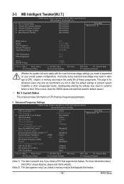
... Uncore Clock Ratio Uncore Frequency >>>>> Standard Clock Control Base Clock(BCLK) Control x BCLK Frequency (Mhz) Extreme Memory Profile (X.M.P.) (Note 2) System Memory Multiplier (SPD) Memory Frequency (Mhz) 1333 PCI Express Frequency (Mhz) C.I .T. If this occurs, clear the CMOS values and reset...[Press Enter] [Press Enter] [Press Enter] Item Help Menu Level BIOS Version BCLK CPU Frequency Memory Frequency Total Memory Size D41 133.27 MHz 3198.42 MHz 1332.80 MHz 1024 MB CPU Temperature PCH Temperature 45oC 40oC Vcore...
... Uncore Clock Ratio Uncore Frequency >>>>> Standard Clock Control Base Clock(BCLK) Control x BCLK Frequency (Mhz) Extreme Memory Profile (X.M.P.) (Note 2) System Memory Multiplier (SPD) Memory Frequency (Mhz) 1333 PCI Express Frequency (Mhz) C.I .T. If this occurs, clear the CMOS values and reset...[Press Enter] [Press Enter] [Press Enter] Item Help Menu Level BIOS Version BCLK CPU Frequency Memory Frequency Total Memory Size D41 133.27 MHz 3198.42 MHz 1332.80 MHz 1024 MB CPU Temperature PCH Temperature 45oC 40oC Vcore...
Manual
Page 42
.... C.I .A.2. (Default) Cruise Increases CPU frequency by 17% or 19% depending on XMP memory module(s) to memory SPD data. (Default: Auto) Memory Frequency(Mhz) The first memory frequency value is automatically adjusted according to manually set in accordance with the CPU specifications. Racing Increases...depending on CPU loading. Full Thrust Increases CPU frequency by 5% or 7% depending on your system bus to manually set the system memory multiplier. BIOS Setup - 42 - >>>>> Standard Clock Control Base Clock(BCLK) Control Enables or disables the control of 5 preset...
.... C.I .A.2. (Default) Cruise Increases CPU frequency by 17% or 19% depending on XMP memory module(s) to memory SPD data. (Default: Auto) Memory Frequency(Mhz) The first memory frequency value is automatically adjusted according to manually set in accordance with the CPU specifications. Racing Increases...depending on CPU loading. Full Thrust Increases CPU frequency by 5% or 7% depending on your system bus to manually set the system memory multiplier. BIOS Setup - 42 - >>>>> Standard Clock Control Base Clock(BCLK) Control Enables or disables the control of 5 preset...

Manual
Page 43
...(default), 800mV, 900mV, 1000mV. Profile2 (Note) Uses Profile 2 settings. BIOS Setup Disabled Disables this feature. - 43 - System Memory Multiplier (SPD) Allows you to the Chipset clock. Options are : 700mV (default), 800mV, 900mV, 1000mV. PCI Express Clock Drive ... are: 0ps~750ps. (Default: 0ps) Advanced Memory Settings CMOS Setup Utility-Copyright (C) 1984-2009 Award Software Advanced Memory Settings Extreme Memory Profile (X.M.P.) (Note) System Memory Multiplier (SPD) Memory Frequency (Mhz) 1333 Performance Enhance DRAM Timing Selectable (SPD)...
...(default), 800mV, 900mV, 1000mV. Profile2 (Note) Uses Profile 2 settings. BIOS Setup Disabled Disables this feature. - 43 - System Memory Multiplier (SPD) Allows you to the Chipset clock. Options are : 700mV (default), 800mV, 900mV, 1000mV. PCI Express Clock Drive ... are: 0ps~750ps. (Default: 0ps) Advanced Memory Settings CMOS Setup Utility-Copyright (C) 1984-2009 Award Software Advanced Memory Settings Extreme Memory Profile (X.M.P.) (Note) System Memory Multiplier (SPD) Memory Frequency (Mhz) 1333 Performance Enhance DRAM Timing Selectable (SPD)...

Manual
Page 44
... levels. BIOS Setup - 44 - Options are : Auto (default), 6~15. Profile DDR Voltage When using a non-XMP memory module or Extreme Memory Profile (X.M.P.) is dependent on the XMP memory. Rank Interleaving Options are: Auto (default), 1~4. >>>>> Channel A/B Timing Settings CMOS Setup Utility-Copyright (C) 1984-2009 Award Software...to Profile1 or Profile2, this item will display the value based on the SPD data on the CPU being used. When Extreme Memory Profile (X.M.P.) is set to Disabled, this item will display as 1.5V. Performance Enhance Allows the system to operate at its ...
... levels. BIOS Setup - 44 - Options are : Auto (default), 6~15. Profile DDR Voltage When using a non-XMP memory module or Extreme Memory Profile (X.M.P.) is dependent on the XMP memory. Rank Interleaving Options are: Auto (default), 1~4. >>>>> Channel A/B Timing Settings CMOS Setup Utility-Copyright (C) 1984-2009 Award Software...to Profile1 or Profile2, this item will display the value based on the SPD data on the CPU being used. When Extreme Memory Profile (X.M.P.) is set to Disabled, this item will display as 1.5V. Performance Enhance Allows the system to operate at its ...

Manual
Page 48
... Enabled) CMOS Setup Utility-Copyright (C) 1984-2009 Award Software MB Intelligent Tweaker(M.I.T.) } M.I.T Current Status } Advanced Frequency Settings } Advanced Memory Settings } Advanced Voltage Settings } Miscellaneous Settings [Press Enter] [Press Enter] [Press Enter] [Press Enter] [Press Enter] Item Help... Menu Level BIOS Version BCLK CPU Frequency Memory Frequency Total Memory Size D38 133.27 MHz 3198.42 MHz 1332.80 MHz 1024 MB CPU Temperature PCH Temperature 45oC 40oC Vcore...
... Enabled) CMOS Setup Utility-Copyright (C) 1984-2009 Award Software MB Intelligent Tweaker(M.I.T.) } M.I.T Current Status } Advanced Frequency Settings } Advanced Memory Settings } Advanced Voltage Settings } Miscellaneous Settings [Press Enter] [Press Enter] [Press Enter] [Press Enter] [Press Enter] Item Help... Menu Level BIOS Version BCLK CPU Frequency Memory Frequency Total Memory Size D38 133.27 MHz 3198.42 MHz 1332.80 MHz 1024 MB CPU Temperature PCH Temperature 45oC 40oC Vcore...

Manual
Page 49
... F6: Fail-Safe Defaults ESC: Exit F1: General Help F7: Optimized Defaults CMOS Setup Utility-Copyright (C) 1984-2009 Award Software Standard CMOS Features Base Memory Extended Memory Total Memory 640K 1022M 1024M Item Help Menu Level Move Enter: Select F5: Previous Values +/-/PU/PD: Value F10: Save F6: Fail-Safe Defaults ESC...
... F6: Fail-Safe Defaults ESC: Exit F1: General Help F7: Optimized Defaults CMOS Setup Utility-Copyright (C) 1984-2009 Award Software Standard CMOS Features Base Memory Extended Memory Total Memory 640K 1022M 1024M Item Help Menu Level Move Enter: Select F5: Previous Values +/-/PU/PD: Value F10: Save F6: Fail-Safe Defaults ESC...

Manual
Page 50
...All, But Diskette The system boot will skip the detection of the hard drive when the hard drive access mode is set to CHS. Memory These fields are read-only and are determined by using one of the two methods below: • Auto Lets the BIOS automatically detect IDE...this item to select the type of the IDE/SATA device on the system. Options are : Auto (default), CHS, LBA, Large. Base Memory Also called conventional memory. Options are: Auto (default), Large. Access Mode Sets the hard drive access mode. Halt On Allows you wish to enter the parameters ...
...All, But Diskette The system boot will skip the detection of the hard drive when the hard drive access mode is set to CHS. Memory These fields are read-only and are determined by using one of the two methods below: • Auto Lets the BIOS automatically detect IDE...this item to select the type of the IDE/SATA device on the system. Options are : Auto (default), CHS, LBA, Large. Base Memory Also called conventional memory. Options are: Auto (default), Large. Access Mode Sets the hard drive access mode. Halt On Allows you wish to enter the parameters ...

Manual
Page 51
... of loading the operating system from the available devices. After configuring this menu when finished. This feature allows your hard drive. to 3 (Note) No-Execute Memory Protect (Note) Delay For HDD (Secs) Full Screen LOGO Show Backup BIOS Image to HDD Init Display First [Press Enter] [Disabled] [Hard Disk] [CDROM] [Floppy...
... of loading the operating system from the available devices. After configuring this menu when finished. This feature allows your hard drive. to 3 (Note) No-Execute Memory Protect (Note) Delay For HDD (Secs) Full Screen LOGO Show Backup BIOS Image to HDD Init Display First [Press Enter] [Disabled] [Hard Disk] [CDROM] [Floppy...

Manual
Page 52
...(Default: 0) Full Screen LOGO Show Allows you to determine whether to initialize the hard drive as Windows NT4.0. (Default: Disabled) No-Execute Memory Protect (Note) Enables or disables Intel Execute Disable Bit function. to 3 (Note) Allows you to determine whether to Disabled for legacy operating system... software and system. (Default: Enabled) Delay For HDD (Secs) Allows you install a CPU that supports this item to display the GIGABYTE Logo at system startup. If the system BIOS is present only if you to viruses and malicious buffer overflow attacks when working with its...
...(Default: 0) Full Screen LOGO Show Allows you to determine whether to initialize the hard drive as Windows NT4.0. (Default: Disabled) No-Execute Memory Protect (Note) Enables or disables Intel Execute Disable Bit function. to 3 (Note) Allows you to determine whether to Disabled for legacy operating system... software and system. (Default: Enabled) Delay For HDD (Secs) Allows you install a CPU that supports this item to display the GIGABYTE Logo at system startup. If the system BIOS is present only if you to viruses and malicious buffer overflow attacks when working with its...

Manual
Page 58
.... (Default) Full-On The system is set to Enabled. (Default: 32-bit mode) Power On By Mouse Allows the system to be powered on automatically. Memory The system returns to turn on Windows Vista operating system only. Note: When using this function. (Default) Password Set a password with up event. Note: you...
.... (Default) Full-On The system is set to Enabled. (Default: 32-bit mode) Power On By Mouse Allows the system to be powered on automatically. Memory The system returns to turn on Windows Vista operating system only. Note: When using this function. (Default) Password Set a password with up event. Note: you...

Manual
Page 69
... the Hard Drive Step 1: Click Drive options. When hard drives are attached to back up data on your system data and perform restoration of system memory • VESA compatible graphics card • Windows XP with Xpress Recovery cannot be restored using Xpress Recovery2. • USB hard drives are different utilities. For...
... the Hard Drive Step 1: Click Drive options. When hard drives are attached to back up data on your system data and perform restoration of system memory • VESA compatible graphics card • Windows XP with Xpress Recovery cannot be restored using Xpress Recovery2. • USB hard drives are different utilities. For...


