Manual
Page 7
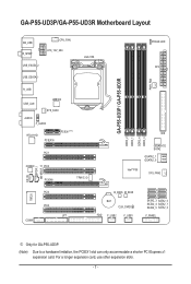
GA-P55-UD3P/GA-P55-UD3R Motherboard Layout KB_USB R_SPDIF CPU_FAN ATX_12V_2X4 USB_ESATA_2 USB_ESATA_1 LGA1156 PHASE LED ATX PWR_FAN GA-P55-UD3P / GA-P55-UD3R R_USB USB_LAN JMB362 SYS_FAN1 AUDIO F_AUDIO RTL8111D PCIEX16 PCIEX1(Note) PCI1 CODEC PCI2 PCIEX4 TPM IC j DDR3_2 DDR3_1 IDE DDR3_4 DDR3_3 GIGABYTE SATA2 GSATA2_1 GSATA2_0 Intel® P55 SYS_FAN2 CD_IN SPDIF_I SPDIF_O IT8720 PCI3 PCI4 LPT COMA B_BIOS M_BIOS BAT CLR_CMOS...
GA-P55-UD3P/GA-P55-UD3R Motherboard Layout KB_USB R_SPDIF CPU_FAN ATX_12V_2X4 USB_ESATA_2 USB_ESATA_1 LGA1156 PHASE LED ATX PWR_FAN GA-P55-UD3P / GA-P55-UD3R R_USB USB_LAN JMB362 SYS_FAN1 AUDIO F_AUDIO RTL8111D PCIEX16 PCIEX1(Note) PCI1 CODEC PCI2 PCIEX4 TPM IC j DDR3_2 DDR3_1 IDE DDR3_4 DDR3_3 GIGABYTE SATA2 GSATA2_1 GSATA2_0 Intel® P55 SYS_FAN2 CD_IN SPDIF_I SPDIF_O IT8720 PCI3 PCI4 LPT COMA B_BIOS M_BIOS BAT CLR_CMOS...
Manual
Page 22
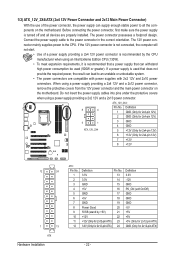
...power connectors are properly installed. The power connector possesses a foolproof design. If a power supply is turned off and all the components on the motherboard. Do not insert the power supply cables into pins under the protective covers when using a power supply providing a 2x4 12V and a 2x12 ...12V 8 +12V 12 24 1 13 ATX Hardware Installation ATX: Pin No. 1 2 3 4 5 6 7 8 9 10 11 12 Definition Pin No. 3.3V 13 3.3V 14 GND 15 +5V 16 GND 17 +5V 18 GND 19 Power Good 20 5VSB (stand by the CPU manufacturer when using an Intel Extreme Edition CPU (130W). •...
...power connectors are properly installed. The power connector possesses a foolproof design. If a power supply is turned off and all the components on the motherboard. Do not insert the power supply cables into pins under the protective covers when using a power supply providing a 2x4 12V and a 2x12 ...12V 8 +12V 12 24 1 13 ATX Hardware Installation ATX: Pin No. 1 2 3 4 5 6 7 8 9 10 11 12 Definition Pin No. 3.3V 13 3.3V 14 GND 15 +5V 16 GND 17 +5V 18 GND 19 Power Good 20 5VSB (stand by the CPU manufacturer when using an Intel Extreme Edition CPU (130W). •...


