Manual
Page 7
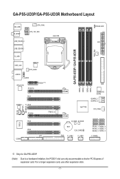
... Layout KB_USB R_SPDIF CPU_FAN ATX_12V_2X4 USB_ESATA_2 USB_ESATA_1 LGA1156 PHASE LED ATX PWR_FAN GA-P55-UD3P / GA-P55-UD3R R_USB USB_LAN JMB362 SYS_FAN1 AUDIO F_AUDIO RTL8111D PCIEX16 PCIEX1(Note) PCI1 CODEC PCI2 PCIEX4 TPM IC j DDR3_2 DDR3_1 IDE DDR3_4 DDR3_3 GIGABYTE SATA2 GSATA2_1 GSATA2_0 Intel® P55 SYS_FAN2 CD_IN SPDIF_I SPDIF_O IT8720 PCI3 PCI4 LPT COMA B_BIOS M_BIOS BAT...
... Layout KB_USB R_SPDIF CPU_FAN ATX_12V_2X4 USB_ESATA_2 USB_ESATA_1 LGA1156 PHASE LED ATX PWR_FAN GA-P55-UD3P / GA-P55-UD3R R_USB USB_LAN JMB362 SYS_FAN1 AUDIO F_AUDIO RTL8111D PCIEX16 PCIEX1(Note) PCI1 CODEC PCI2 PCIEX4 TPM IC j DDR3_2 DDR3_1 IDE DDR3_4 DDR3_3 GIGABYTE SATA2 GSATA2_1 GSATA2_0 Intel® P55 SYS_FAN2 CD_IN SPDIF_I SPDIF_O IT8720 PCI3 PCI4 LPT COMA B_BIOS M_BIOS BAT...
Manual
Page 11
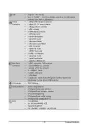
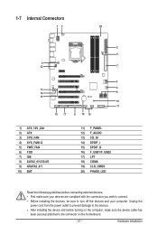
... Chipset Up to 14 USB 2.0/1.1 ports (10 on the back panel, 4 via the USB brackets connected to the internal USB headers) 1 x 24-pin ATX main power connector 1 x 8-pin ATX 12V power connector 1 x floppy disk drive connector 1 x IDE connector 8 x SATA 3Gb/s connectors 1 x CPU fan header 2 x system fan headers 1 x power fan header 1 x front panel...
... Chipset Up to 14 USB 2.0/1.1 ports (10 on the back panel, 4 via the USB brackets connected to the internal USB headers) 1 x 24-pin ATX main power connector 1 x 8-pin ATX 12V power connector 1 x floppy disk drive connector 1 x IDE connector 8 x SATA 3Gb/s connectors 1 x CPU fan header 2 x system fan headers 1 x power fan header 1 x front panel...
Manual
Page 12
... 6™ Support for Q-Share Norton Internet Security (OEM version) Operating System w Support for Microsoft® Windows® 7/Vista/XP Form Factor w ATX Form Factor; 30.5cm x 24.4cm j Only for GA-P55-UD3P. (Note 1) Due to Windows Vista/XP 32-bit operating system limitation, when more than 4 GB of physical memory is installed...
... 6™ Support for Q-Share Norton Internet Security (OEM version) Operating System w Support for Microsoft® Windows® 7/Vista/XP Form Factor w ATX Form Factor; 30.5cm x 24.4cm j Only for GA-P55-UD3P. (Note 1) Due to Windows Vista/XP 32-bit operating system limitation, when more than 4 GB of physical memory is installed...
Manual
Page 21
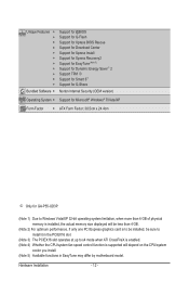
1-7 Internal Connectors 13 20 2 5 4 12 7 9 13 4 14 8 15 19 11 18 17 6 10 16 1) ATX_12V_2X4 2) ATX 3) CPU_FAN 4) SYS_FAN1/2 5) PWR_FAN 6) FDD 7) IDE 8) SATA2_0/1/2/3/4/5 9) GSATA2_0/1 10) BAT 11) F_PANEL 12) F_AUDIO 13) CD_IN 14) SPDIF_I 15) SPDIF_O 16) F_USB1/F_USB2 17) LPT 18) ...
1-7 Internal Connectors 13 20 2 5 4 12 7 9 13 4 14 8 15 19 11 18 17 6 10 16 1) ATX_12V_2X4 2) ATX 3) CPU_FAN 4) SYS_FAN1/2 5) PWR_FAN 6) FDD 7) IDE 8) SATA2_0/1/2/3/4/5 9) GSATA2_0/1 10) BAT 11) F_PANEL 12) F_AUDIO 13) CD_IN 14) SPDIF_I 15) SPDIF_O 16) F_USB1/F_USB2 17) LPT 18) ...
Manual
Page 22
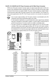
... 2x4-pin 12V) 3 GND 4 GND 5 +12V (Only for 2x4-pin 12V) 6 +12V (Only for 2x4-pin 12V) 7 +12V 8 +12V 12 24 1 13 ATX Hardware Installation ATX: Pin No. 1 2 3 4 5 6 7 8 9 10 11 12 Definition Pin No. 3.3V 13 3.3V 14 GND 15 +5V 16 GND 17 +5V 18 GND ... by the CPU manufacturer when using a power supply providing a 2x2 12V and a 2x10 power connector. 8 4 5 1 ATX_12V_2X4 ATX_12V_2X4: Pin No. 1/2) ATX_12V_2X4/ATX (2x4 12V Power Connector and 2x12 Main Power Connector) With the use of a power supply providing a 2x4 12V power connector is used (500W or greater).
... 2x4-pin 12V) 3 GND 4 GND 5 +12V (Only for 2x4-pin 12V) 6 +12V (Only for 2x4-pin 12V) 7 +12V 8 +12V 12 24 1 13 ATX Hardware Installation ATX: Pin No. 1 2 3 4 5 6 7 8 9 10 11 12 Definition Pin No. 3.3V 13 3.3V 14 GND 15 +5V 16 GND 17 +5V 18 GND ... by the CPU manufacturer when using a power supply providing a 2x2 12V and a 2x10 power connector. 8 4 5 1 ATX_12V_2X4 ATX_12V_2X4: Pin No. 1/2) ATX_12V_2X4/ATX (2x4 12V Power Connector and 2x12 Main Power Connector) With the use of a power supply providing a 2x4 12V power connector is used (500W or greater).

Manual
Page 54
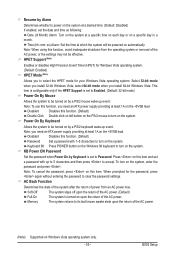
...-up signal from a PCI or PCIe device. In S3 sleep state, the system appears to turn off . Note: To use this function, you need an ATX power supply providing at any time. In S1 sleep state, the system appears suspended and stays in MS-DOS mode using the power button. Press...
...-up signal from a PCI or PCIe device. In S3 sleep state, the system appears to turn off . Note: To use this function, you need an ATX power supply providing at any time. In S1 sleep state, the system appears suspended and stays in MS-DOS mode using the power button. Press...
Manual
Page 55
... By Mouse Allows the system to be turned on by a PS/2 keyboard wake-up to 5 characters and then press to accept. Note: you need an ATX power supply providing at least 1A on the +5VSB lead. Time (hh: mm: ss) Alarm: Set the time at which the system will be effective.... Press on this function, you need an ATX power supply providing at least 1A on the +5VSB lead. AC Back Function Determines the state of the system after the return of the AC...
... By Mouse Allows the system to be turned on by a PS/2 keyboard wake-up to 5 characters and then press to accept. Note: you need an ATX power supply providing at least 1A on the +5VSB lead. Time (hh: mm: ss) Alarm: Set the time at which the system will be effective.... Press on this function, you need an ATX power supply providing at least 1A on the +5VSB lead. AC Back Function Determines the state of the system after the return of the AC...

Manual
Page 117
... memory socket. Make sure the graphics card is verified and solved. Secure the CPU cooler No on the CPU. Insert the graphics card. Connect the ATX main power cable and the 12V power cable. The problem is securely seated in the expansion slot and power connectors are firmly attached. Connect the...
... memory socket. Make sure the graphics card is verified and solved. Secure the CPU cooler No on the CPU. Insert the graphics card. Connect the ATX main power cable and the 12V power cable. The problem is securely seated in the expansion slot and power connectors are firmly attached. Connect the...
