
Manual
Page 1
... in the array. ) 1. Or you have to the biggest drive in the Intel Chipset. (Note 2) It is greater than or equal to load the SATA controller driver first. Using GIGABYTE eXtreme Hard Drive (X.H.D) Instructions:(Note 2) Before launching X.H.D, make sure the new drive... screen to automatically and quickly set up a RAID 0 array. 2. eXtreme Hard Drive (X.H.D) With GIGABYTE eXtreme Hard Drive (X.H.D)(Note 1), users can quickly configure a RAIDready system for the Intel SATA controllers. The following procedure details the steps to expand its capacity. B. Without the driver, ...
... in the array. ) 1. Or you have to the biggest drive in the Intel Chipset. (Note 2) It is greater than or equal to load the SATA controller driver first. Using GIGABYTE eXtreme Hard Drive (X.H.D) Instructions:(Note 2) Before launching X.H.D, make sure the new drive... screen to automatically and quickly set up a RAID 0 array. 2. eXtreme Hard Drive (X.H.D) With GIGABYTE eXtreme Hard Drive (X.H.D)(Note 1), users can quickly configure a RAIDready system for the Intel SATA controllers. The following procedure details the steps to expand its capacity. B. Without the driver, ...
Manual
Page 1
GA-P55-UD3P GA-P55-UD3R LGA1156 socket motherboard for Intel® Core™ i7 processor family/ Intel® Core™ i5 processor family User's Manual Rev. 1001 12ME-P55UD3P-1001R
GA-P55-UD3P GA-P55-UD3R LGA1156 socket motherboard for Intel® Core™ i7 processor family/ Intel® Core™ i5 processor family User's Manual Rev. 1001 12ME-P55UD3P-1001R
Manual
Page 5
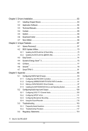
...8482; 2 75 4-5 Q-Share...77 4-6 Smart 6™ ...78 4-7 Smart TPM j 81 Chapter 5 Appendix...83 5-1 Configuring SATA Hard Drive(s 83 5-1-1 Configuring Intel P55 SATA Controllers 83 5-1-2 Configuring JMB362/GIGABYTE SATA2 SATA Controller 91 5-1-3 Making a SATA RAID/AHCI Driver Diskette 97 5-1-4 Installing the SATA RAID/AHCI Driver and Operating System 98 5-2 Configuring Audio... Recording 113 5-2-4 Using the Sound Recorder 115 5-3 Troubleshooting 116 5-3-1 Frequently Asked Questions 116 5-3-2 Troubleshooting Procedure 117 5-4 Regulatory Statements 119 j Only for GA-P55-UD3P. - 5 -
...8482; 2 75 4-5 Q-Share...77 4-6 Smart 6™ ...78 4-7 Smart TPM j 81 Chapter 5 Appendix...83 5-1 Configuring SATA Hard Drive(s 83 5-1-1 Configuring Intel P55 SATA Controllers 83 5-1-2 Configuring JMB362/GIGABYTE SATA2 SATA Controller 91 5-1-3 Making a SATA RAID/AHCI Driver Diskette 97 5-1-4 Installing the SATA RAID/AHCI Driver and Operating System 98 5-2 Configuring Audio... Recording 113 5-2-4 Using the Sound Recorder 115 5-3 Troubleshooting 116 5-3-1 Frequently Asked Questions 116 5-3-2 Troubleshooting Procedure 117 5-4 Regulatory Statements 119 j Only for GA-P55-UD3P. - 5 -
Manual
Page 7
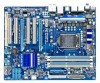
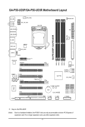
... card, use other expansion slots. - 7 - GA-P55-UD3P/GA-P55-UD3R Motherboard Layout KB_USB R_SPDIF CPU_FAN ATX_12V_2X4 USB_ESATA_2 USB_ESATA_1 LGA1156 PHASE LED ATX PWR_FAN GA-P55-UD3P / GA-P55-UD3R R_USB USB_LAN JMB362 SYS_FAN1 AUDIO F_AUDIO RTL8111D PCIEX16 PCIEX1(Note) PCI1 CODEC PCI2 PCIEX4 TPM IC j DDR3_2 DDR3_1 IDE DDR3_4 DDR3_3 GIGABYTE SATA2 GSATA2_1 GSATA2_0 Intel® P55 SYS_FAN2 CD_IN SPDIF_I SPDIF_O IT8720...
... card, use other expansion slots. - 7 - GA-P55-UD3P/GA-P55-UD3R Motherboard Layout KB_USB R_SPDIF CPU_FAN ATX_12V_2X4 USB_ESATA_2 USB_ESATA_1 LGA1156 PHASE LED ATX PWR_FAN GA-P55-UD3P / GA-P55-UD3R R_USB USB_LAN JMB362 SYS_FAN1 AUDIO F_AUDIO RTL8111D PCIEX16 PCIEX1(Note) PCI1 CODEC PCI2 PCIEX4 TPM IC j DDR3_2 DDR3_1 IDE DDR3_4 DDR3_3 GIGABYTE SATA2 GSATA2_1 GSATA2_0 Intel® P55 SYS_FAN2 CD_IN SPDIF_I SPDIF_O IT8720...
Manual
Page 8
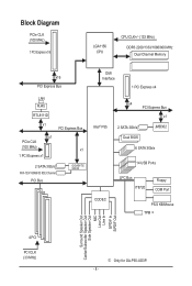
... Bus x1 PCIe CLK (100 MHz) x1 1 PCI Express x1 2 SATA 3Gb/s ATA-133/100/66/33 IDE Channel PCI Bus GIGABYTE SATA2 DMI Interface 1 PCI Express x4 Intel® P55 x4 PCI Express Bus x1 2 SATA 3Gb/s Dual BIOS JMB362 6 SATA 3Gb/s 14 USB Ports CODEC LPC Bus IT8720 Floppy COM Port... Speaker Out Center/Subwoofer Speaker Out Side Speaker Out MIC Line Out Line In S/PDIF In S/PDIF Out 4 PCI PCI CLK (33 MHz) j Only for GA-P55-UD3P. - 8 -
... Bus x1 PCIe CLK (100 MHz) x1 1 PCI Express x1 2 SATA 3Gb/s ATA-133/100/66/33 IDE Channel PCI Bus GIGABYTE SATA2 DMI Interface 1 PCI Express x4 Intel® P55 x4 PCI Express Bus x1 2 SATA 3Gb/s Dual BIOS JMB362 6 SATA 3Gb/s 14 USB Ports CODEC LPC Bus IT8720 Floppy COM Port... Speaker Out Center/Subwoofer Speaker Out Side Speaker Out MIC Line Out Line In S/PDIF In S/PDIF Out 4 PCI PCI CLK (33 MHz) j Only for GA-P55-UD3P. - 8 -
Manual
Page 10
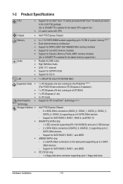
...Support for an Intel® Core™ i7 series processor/Intel® Core™ i5 series processor in the LGA1156 package (Go to GIGABYTE's website for the latest CPU support list.) L3 cache varies with CPU Chipset Intel® P55 Express Chipset ... x1 slot 4 x PCI slots Multi-Graphics Support for ATI CrossFireX™ technology (Note 3) Technology Storage Interface Intel® P55 Express Chipset: - 6 x SATA 3Gb/s connectors (SATA2_0, SATA2_1, SATA2_2, SATA2_3, SATA2_4, SATA2_5) supporting up to 1 floppy disk drive Hardware...
...Support for an Intel® Core™ i7 series processor/Intel® Core™ i5 series processor in the LGA1156 package (Go to GIGABYTE's website for the latest CPU support list.) L3 cache varies with CPU Chipset Intel® P55 Express Chipset ... x1 slot 4 x PCI slots Multi-Graphics Support for ATI CrossFireX™ technology (Note 3) Technology Storage Interface Intel® P55 Express Chipset: - 6 x SATA 3Gb/s connectors (SATA2_0, SATA2_1, SATA2_2, SATA2_3, SATA2_4, SATA2_5) supporting up to 1 floppy disk drive Hardware...

Manual
Page 15
... the contrary, is complete. 1-3-2 Installing the CPU Cooler Follow the steps below to correctly install the CPU cooler on the motherboard. (The following procedure uses Intel® boxed cooler as the picture above shows, the installation is to install.) Step 3: Place the cooler atop the CPU, aligning the four push pins...
... the contrary, is complete. 1-3-2 Installing the CPU Cooler Follow the steps below to correctly install the CPU cooler on the motherboard. (The following procedure uses Intel® boxed cooler as the picture above shows, the installation is to install.) Step 3: Place the cooler atop the CPU, aligning the four push pins...
Manual
Page 22
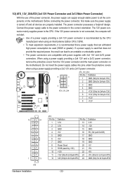
... 13 3.3V 14 GND 15 +5V 16 GND 17 +5V 18 GND 19 Power Good 20 5VSB (stand by the CPU manufacturer when using an Intel Extreme Edition CPU (130W). • To meet expansion requirements, it is recommended that a power supply that does not provide the required power, the result can...
... 13 3.3V 14 GND 15 +5V 16 GND 17 +5V 18 GND 19 Power Good 20 5VSB (stand by the CPU manufacturer when using an Intel Extreme Edition CPU (130W). • To meet expansion requirements, it is recommended that a power supply that does not provide the required power, the result can...
Manual
Page 27
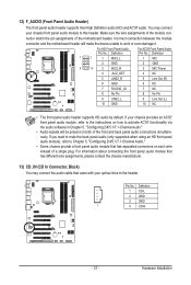
... 2/4/5.1/7.1-Channel Audio." • Audio signals will make the device unable to this header. 12) F_AUDIO (Front Panel Audio Header) The front panel audio header supports Intel High Definition audio (HD) and AC'97 audio.
... 2/4/5.1/7.1-Channel Audio." • Audio signals will make the device unable to this header. 12) F_AUDIO (Front Panel Audio Header) The front panel audio header supports Intel High Definition audio (HD) and AC'97 audio.

Manual
Page 37
... Defaults ESC: Exit F1: General Help F7: Optimized Defaults (Note 1) This item is dependent on your overall system configurations. For more information about Intel CPUs' unique features, please visit Intel's website. (Note 2) This item appears only if you install a CPU that supports this occurs, clear the CMOS values and reset the board...
... Defaults ESC: Exit F1: General Help F7: Optimized Defaults (Note 1) This item is dependent on your overall system configurations. For more information about Intel CPUs' unique features, please visit Intel's website. (Note 2) This item appears only if you install a CPU that supports this occurs, clear the CMOS values and reset the board...
Manual
Page 38
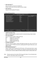
...the CPU core frequency and voltage will be reduced during system halt state to decrease power consumption. For more information about Intel CPUs' unique features, please visit Intel's website. Auto lets the BIOS automatically configure this setting. (Default: Auto) (Note) This item is installed. ...the current operating CPU frequency. Advanced CPU Core Features CMOS Setup Utility-Copyright (C) 1984-2009 Award Software Advanced CPU Core Features Intel(R) Turbo Boost Tech. CPU Clock Ratio (Note) Allows you to determine whether to enable all CPU cores. (Default) 1 Enables only...
...the CPU core frequency and voltage will be reduced during system halt state to decrease power consumption. For more information about Intel CPUs' unique features, please visit Intel's website. Auto lets the BIOS automatically configure this setting. (Default: Auto) (Note) This item is installed. ...the current operating CPU frequency. Advanced CPU Core Features CMOS Setup Utility-Copyright (C) 1984-2009 Award Software Advanced CPU Core Features Intel(R) Turbo Boost Tech. CPU Clock Ratio (Note) Allows you to determine whether to enable all CPU cores. (Default) 1 Enables only...

Manual
Page 39
...emit PROCHOT signals. Auto lets the BIOS automatically configure this setting. (Default: Auto) CPU Thermal Monitor (Note) Enables or disables Intel CPU Thermal Monitor function, a CPU overheating protection function. Auto lets the BIOS automatically configure this setting. (Default: Auto) Bi-...production. Auto lets the BIOS automatically configure this setting. (Default: Auto) CPU EIST Function (Note) Enables or disables Enhanced Intel SpeedStep Technology (EIST). When enabled, the CPU core frequency and voltage will be reduced when the CPU is occurring to decrease...
...emit PROCHOT signals. Auto lets the BIOS automatically configure this setting. (Default: Auto) CPU Thermal Monitor (Note) Enables or disables Intel CPU Thermal Monitor function, a CPU overheating protection function. Auto lets the BIOS automatically configure this setting. (Default: Auto) Bi-...production. Auto lets the BIOS automatically configure this setting. (Default: Auto) CPU EIST Function (Note) Enables or disables Enhanced Intel SpeedStep Technology (EIST). When enabled, the CPU core frequency and voltage will be reduced when the CPU is occurring to decrease...
Manual
Page 45
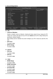
... default is Auto. >>> DRAM DRAM Voltage The default is Auto. DRAM Termination The default is Auto. Ch-A Data VRef. Disabled sets the CPU voltage following Intel specifications. (Default: Disabled) Note: Enabling Load-Line Calibration may result in damage to your CPU or reduce the useful life of the CPU. CPU Vcore...
... default is Auto. >>> DRAM DRAM Voltage The default is Auto. DRAM Termination The default is Auto. Ch-A Data VRef. Disabled sets the CPU voltage following Intel specifications. (Default: Disabled) Note: Enabling Load-Line Calibration may result in damage to your CPU or reduce the useful life of the CPU. CPU Vcore...
Manual
Page 49
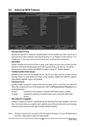
... 3 (Note) No-Execute Memory Protect (Note) Delay For HDD (Secs) Full Screen LOGO Show Backup BIOS Image to accept. For more information about Intel CPUs' unique features, please visit Intel's website. - 49 - After configuring this item, set the password(s) under the Set Supervisor/User Password item in the BIOS Main Menu. 2-5 Advanced...
... 3 (Note) No-Execute Memory Protect (Note) Delay For HDD (Secs) Full Screen LOGO Show Backup BIOS Image to accept. For more information about Intel CPUs' unique features, please visit Intel's website. - 49 - After configuring this item, set the password(s) under the Set Supervisor/User Password item in the BIOS Main Menu. 2-5 Advanced...
Manual
Page 50
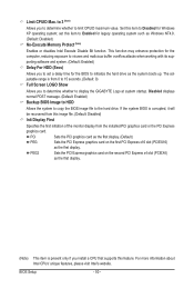
... 0) Full Screen LOGO Show Allows you to determine whether to limit CPUID maximum value. The ad- For more information about Intel CPUs' unique features, please visit Intel's website. This function may enhance protection for Windows XP operating system; Set this feature. PEG2 Sets the PCI Express graphics ... normal POST message. (Default: Enabled) Backup BIOS Image to HDD Allows the system to copy the BIOS image file to display the GIGABYTE Logo at system startup. PCI Sets the PCI graphics card as the first display. (Default) PEG Sets the PCI Express graphics card on...
... 0) Full Screen LOGO Show Allows you to determine whether to limit CPUID maximum value. The ad- For more information about Intel CPUs' unique features, please visit Intel's website. This function may enhance protection for Windows XP operating system; Set this feature. PEG2 Sets the PCI Express graphics ... normal POST message. (Default: Enabled) Backup BIOS Image to HDD Allows the system to copy the BIOS image file to display the GIGABYTE Logo at system startup. PCI Sets the PCI graphics card as the first display. (Default) PEG Sets the PCI Express graphics card on...

Manual
Page 51
...F10: Save F6: Fail-Safe Defaults ESC: Exit F1: General Help F7: Optimized Defaults SATA RAID/AHCI Mode (Intel P55 Chipset) Enables or disables RAID for the SATA controllers integrated in the Intel P55 chipset or configures the SATA controllers to AHCI mode. USB Controllers Enables or disables the integrated USB 1.0 controller. (... that do not support Native mode. (Default) Enabled Allows the SATA controllers to be shared with other device. SATA Port0-3 Native Mode (Intel P55 Chipset) Specifies the operating mode of the USB functionalities below.
...F10: Save F6: Fail-Safe Defaults ESC: Exit F1: General Help F7: Optimized Defaults SATA RAID/AHCI Mode (Intel P55 Chipset) Enables or disables RAID for the SATA controllers integrated in the Intel P55 chipset or configures the SATA controllers to AHCI mode. USB Controllers Enables or disables the integrated USB 1.0 controller. (... that do not support Native mode. (Default) Enabled Allows the SATA controllers to be shared with other device. SATA Port0-3 Native Mode (Intel P55 Chipset) Specifies the operating mode of the USB functionalities below.

Manual
Page 57
... control mode. (Default) Voltage Sets Voltage mode for a 4-pin CPU fan. This item is configurable only if CPU Smart FAN Control is not designed following Intel PWM fan specifications, selecting PWM mode may not effectively reduce the fan speed. - 57 -
... control mode. (Default) Voltage Sets Voltage mode for a 4-pin CPU fan. This item is configurable only if CPU Smart FAN Control is not designed following Intel PWM fan specifications, selecting PWM mode may not effectively reduce the fan speed. - 57 -
Manual
Page 83
...hard drive. • An empty formatted floppy disk. • Windows Vista/XP setup disk. • Motherboard driver disk. 5-1-1 Configuring Intel P55 SATA Controllers A. Install SATA hard drive(s) in your computer Attach one SATA controller on your motherboard, refer to "Chapter 1," "Hardware ... the hard drive. (Note 1) Skip this motherboard, the SATA2_0, SATA2_1, SATA2_2, SATA2_3, SATA2_4 and SATA2_5 ports are supported by P55 Chipset.) Then connect the power connector from your computer. Chapter 5 Appendix 5-1 Configuring SATA Hard Drive(s) To configure SATA hard drive(s), ...
...hard drive. • An empty formatted floppy disk. • Windows Vista/XP setup disk. • Motherboard driver disk. 5-1-1 Configuring Intel P55 SATA Controllers A. Install SATA hard drive(s) in your computer Attach one SATA controller on your motherboard, refer to "Chapter 1," "Hardware ... the hard drive. (Note 1) Skip this motherboard, the SATA2_0, SATA2_1, SATA2_2, SATA2_3, SATA2_4 and SATA2_5 ports are supported by P55 Chipset.) Then connect the power connector from your computer. Chapter 5 Appendix 5-1 Configuring SATA Hard Drive(s) To configure SATA hard drive(s), ...

Manual
Page 85
... Size 111.7GB 111.7GB Type/Status(Vol ID) Non-RAID Disk Non-RAID Disk Press to Non-RAID 4. Intel(R) Matrix Storage Manager option ROM v8.9.0.1023 PCH-D wRAID5 Copyright(C) 2003-09 Intel Corporation. All Rights Reserved. [ MAIN MENU ] 1. Reset Disks to enter Configuration Utility.. All Rights Reserved. Delete RAID...]-Select [ESC]-Exit Figure 3 [ENTER]-Select Menu - 85 - Appendix Exit 3. RAID Volumes : None defined. C. Configuring a RAID array in MAIN MENU and press . Intel(R) Matrix Storage Manager option ROM v8.9.0.1023 PCH-D wRAID5 Copyright(C) 2003-09...
... Size 111.7GB 111.7GB Type/Status(Vol ID) Non-RAID Disk Non-RAID Disk Press to Non-RAID 4. Intel(R) Matrix Storage Manager option ROM v8.9.0.1023 PCH-D wRAID5 Copyright(C) 2003-09 Intel Corporation. All Rights Reserved. [ MAIN MENU ] 1. Reset Disks to enter Configuration Utility.. All Rights Reserved. Delete RAID...]-Select [ESC]-Exit Figure 3 [ENTER]-Select Menu - 85 - Appendix Exit 3. RAID Volumes : None defined. C. Configuring a RAID array in MAIN MENU and press . Intel(R) Matrix Storage Manager option ROM v8.9.0.1023 PCH-D wRAID5 Copyright(C) 2003-09...

Manual
Page 86
... data and stripes the mirror. Set the stripe block size (Figure 5) if necessary. Intel(R) Matrix Storage Manager option ROM v8.9.0.1023 PCH-D wRAID5 Copyright(C) 2003-09 Intel Corporation. Intel(R) Matrix Storage Manager option ROM v8.9.0.1023 PCH-D wRAID5 Copyright(C) 2003-09 Intel Corporation. Recovery: Copies data between a master and a recovery disk. If only two...
... data and stripes the mirror. Set the stripe block size (Figure 5) if necessary. Intel(R) Matrix Storage Manager option ROM v8.9.0.1023 PCH-D wRAID5 Copyright(C) 2003-09 Intel Corporation. Intel(R) Matrix Storage Manager option ROM v8.9.0.1023 PCH-D wRAID5 Copyright(C) 2003-09 Intel Corporation. Recovery: Copies data between a master and a recovery disk. If only two...


