Manual
Page 7
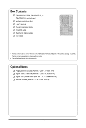
Box Contents GA-P55-UD3L-TPM, GA-P55-UD3L, or GA-P55-US3L motherboard Motherboard driver disk User's Manual Quick Installation Guide One IDE cable Two SATA 3Gb/s cables I/O Shield • The box contents above are subject ... depend on the product package you obtain. The box contents are for reference only. Optional Items Floppy disk drive cable (Part No. 12CF1-1FD001-7*R) 2-port USB 2.0 bracket (Part No. 12CR1-1UB030-5*R) 2-port SATA power cable (Part No. 12CF1-2SERPW-0*R) S/PDIF In cable (Part No. 12CR1-1SPDIN-0*R) - 7 -
Box Contents GA-P55-UD3L-TPM, GA-P55-UD3L, or GA-P55-US3L motherboard Motherboard driver disk User's Manual Quick Installation Guide One IDE cable Two SATA 3Gb/s cables I/O Shield • The box contents above are subject ... depend on the product package you obtain. The box contents are for reference only. Optional Items Floppy disk drive cable (Part No. 12CF1-1FD001-7*R) 2-port USB 2.0 bracket (Part No. 12CR1-1UB030-5*R) 2-port SATA power cable (Part No. 12CF1-2SERPW-0*R) S/PDIF In cable (Part No. 12CR1-1SPDIN-0*R) - 7 -
Manual
Page 9
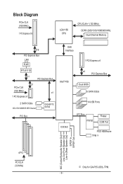
... MHz) x1 1 PCI Express x1 2 SATA 3Gb/s ATA-133/100/66/33 IDE Channel GIGABYTE SATA2 PCI Bus DMI Interface 1 PCI Express x4 Intel® P55 x4 PCI Express Bus Dual BIOS 6 SATA 3Gb/s 14 USB Ports CODEC LPC Bus IT8720 Floppy COM Port PS/2 KB/Mouse TPM j MIC (Center/Subwoofer Speaker... Out) Line-Out (Front Speaker Out) Line-In (Rear Speaker Out) S/PDIF In S/PDIF Out 4 PCI PCI CLK (33 MHz) j Only for GA-P55-UD3L-TPM. - 9...
... MHz) x1 1 PCI Express x1 2 SATA 3Gb/s ATA-133/100/66/33 IDE Channel GIGABYTE SATA2 PCI Bus DMI Interface 1 PCI Express x4 Intel® P55 x4 PCI Express Bus Dual BIOS 6 SATA 3Gb/s 14 USB Ports CODEC LPC Bus IT8720 Floppy COM Port PS/2 KB/Mouse TPM j MIC (Center/Subwoofer Speaker... Out) Line-Out (Front Speaker Out) Line-In (Rear Speaker Out) S/PDIF In S/PDIF Out 4 PCI PCI CLK (33 MHz) j Only for GA-P55-UD3L-TPM. - 9...

Manual
Page 13
...1 x front panel audio header w 1 x CD In connector w 1 x S/PDIF In header w 1 x S/PDIF Out header w 3 x USB 2.0/1.1 headers w 1 x clearing CMOS jumper Back Panel w 1 x PS/2 keyboard or PS/2 mouse port Connectors w 1 x coaxial S/PDIF Out connector w 1 x parallel port w ...1 x serial port w 8 x USB 2.0/1.1 ports w 1 x RJ-45 port w 3 x audio jacks (Line In/Line Out/Microphone) I/O Controller w iTE IT8720 chip Hardware Monitor w...
...1 x front panel audio header w 1 x CD In connector w 1 x S/PDIF In header w 1 x S/PDIF Out header w 3 x USB 2.0/1.1 headers w 1 x clearing CMOS jumper Back Panel w 1 x PS/2 keyboard or PS/2 mouse port Connectors w 1 x coaxial S/PDIF Out connector w 1 x parallel port w ...1 x serial port w 8 x USB 2.0/1.1 ports w 1 x RJ-45 port w 3 x audio jacks (Line In/Line Out/Microphone) I/O Controller w iTE IT8720 chip Hardware Monitor w...
Manual
Page 21
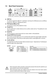
...a printer port. The following describes the states of the LAN port LEDs. PS/2 Keyboard/Mouse Port Use this port for USB devices such as a USB keyboard/mouse, USB printer, USB flash drive and etc. Parallel Port Use the parallel port to a back panel connector, first remove the cable from the ... audio system provides a coaxial digital audio in connector. Hardware Installation Use this port to 1 Gbps data rate. 1-6 Back Panel Connectors USB Port The USB port supports the USB 2.0/1.1 specification. Before using this feature, ensure that supports digital coaxial audio.
...a printer port. The following describes the states of the LAN port LEDs. PS/2 Keyboard/Mouse Port Use this port for USB devices such as a USB keyboard/mouse, USB printer, USB flash drive and etc. Parallel Port Use the parallel port to a back panel connector, first remove the cable from the ... audio system provides a coaxial digital audio in connector. Hardware Installation Use this port to 1 Gbps data rate. 1-6 Back Panel Connectors USB Port The USB port supports the USB 2.0/1.1 specification. Before using this feature, ensure that supports digital coaxial audio.

Manual
Page 31
...defaults (select Load Optimized Defaults) or manually configure the BIOS settings (refer to USB 2.0/1.1 specification. For purchasing the optional USB bracket, please contact the local dealer. Definition 1 Power (5V) 9 1 2 Power (5V) 10 2 3 USB DX- 4 USB DY- 5 USB DX+ 6 USB DY+ 7 GND 8 GND 9 No Pin 10 NC • Do ... CMOS Values • Always turn off your computer and unplug the power cord from the power outlet to prevent damage to the USB bracket. 17) CLR_CMOS (Clearing CMOS Jumper) Use this jumper to remove the jumper cap from the power outlet before clearing the CMOS...
...defaults (select Load Optimized Defaults) or manually configure the BIOS settings (refer to USB 2.0/1.1 specification. For purchasing the optional USB bracket, please contact the local dealer. Definition 1 Power (5V) 9 1 2 Power (5V) 10 2 3 USB DX- 4 USB DY- 5 USB DX+ 6 USB DY+ 7 GND 8 GND 9 No Pin 10 NC • Do ... CMOS Values • Always turn off your computer and unplug the power cord from the power outlet to prevent damage to the USB bracket. 17) CLR_CMOS (Clearing CMOS Jumper) Use this jumper to remove the jumper cap from the power outlet before clearing the CMOS...
Manual
Page 36
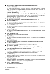
... defaults are factory settings for the most stable, minimal-performance system operations. Load Optimized Defaults Optimized defaults are factory settings for GA-P55-UD3L-TPM. j Only for optimal-performance system operations. Set Supervisor Password Change, set , or disable password. It allows you..., and the primary display adapter. Integrated Peripherals Use this menu to configure all peripheral devices, such as IDE, SATA, USB, integrated audio, and integrated LAN, etc. Power Management Setup Use this menu to configure the TPM function. Pressing to ...
... defaults are factory settings for the most stable, minimal-performance system operations. Load Optimized Defaults Optimized defaults are factory settings for GA-P55-UD3L-TPM. j Only for optimal-performance system operations. Set Supervisor Password Change, set , or disable password. It allows you..., and the primary display adapter. Integrated Peripherals Use this menu to configure all peripheral devices, such as IDE, SATA, USB, integrated audio, and integrated LAN, etc. Power Management Setup Use this menu to configure the TPM function. Pressing to ...
Manual
Page 49
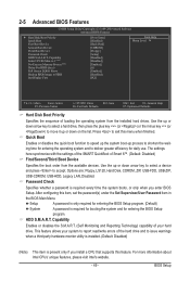
...: Disabled) First/Second/Third Boot Device Specifies the boot order from the installed hard drives. Options are: Floppy, LS120, Hard Disk, CDROM, ZIP, USB-FDD, USB-ZIP, USB-CDROM, USB-HDD, Legacy LAN, Disabled. BIOS Setup After configuring this menu when finished. Use the up or down arrow key to select a hard drive, then...
...: Disabled) First/Second/Third Boot Device Specifies the boot order from the installed hard drives. Options are: Floppy, LS120, Hard Disk, CDROM, ZIP, USB-FDD, USB-ZIP, USB-CDROM, USB-HDD, Legacy LAN, Disabled. BIOS Setup After configuring this menu when finished. Use the up or down arrow key to select a hard drive, then...
Manual
Page 51
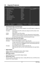
...Intel P55 Chipset) Specifies the operating mode of the USB functionalities below. BIOS Setup Set this option to Disabled if you wish to enable advanced Serial ATA features such as Native Command Queuing and hot plug. USB Controllers Enables or disables the integrated USB ...CMOS Setup Utility-Copyright (C) 1984-2009 Award Software Integrated Peripherals SATA RAID/AHCI Mode SATA Port0-3 Native Mode USB Controllers USB Legacy Function USB Storage Function Azalia Codec Onboard H/W LAN Green LAN } SMART LAN Onboard LAN Boot ROM Onboard SATA/IDE...
...Intel P55 Chipset) Specifies the operating mode of the USB functionalities below. BIOS Setup Set this option to Disabled if you wish to enable advanced Serial ATA features such as Native Command Queuing and hot plug. USB Controllers Enables or disables the integrated USB ...CMOS Setup Utility-Copyright (C) 1984-2009 Award Software Integrated Peripherals SATA RAID/AHCI Mode SATA Port0-3 Native Mode USB Controllers USB Legacy Function USB Storage Function Azalia Codec Onboard H/W LAN Green LAN } SMART LAN Onboard LAN Boot ROM Onboard SATA/IDE...
Manual
Page 63
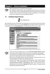
... • Some device drivers will restart your mouse and select Uninstall) and restart the system. (The system will then autodetect and install the USB 2.0 driver.) - 63 - Drivers Installation You can install other drivers. • After the drivers are recommended to restart your system. the ...Drivers After inserting the driver disk, "Xpress Install" will install all the drivers that shown in the motherboard driver disk. • For USB 2.0 driver support under the Windows XP operating system, please install the Windows XP Service Pack 1 or later. The driver Autorun screen is ...
... • Some device drivers will restart your mouse and select Uninstall) and restart the system. (The system will then autodetect and install the USB 2.0 driver.) - 63 - Drivers Installation You can install other drivers. • After the drivers are recommended to restart your system. the ...Drivers After inserting the driver disk, "Xpress Install" will install all the drivers that shown in the motherboard driver disk. • For USB 2.0 driver support under the Windows XP operating system, please install the Windows XP Service Pack 1 or later. The driver Autorun screen is ...
Manual
Page 67
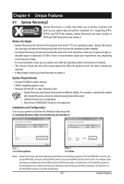
...; At least 512 MB of system memory • VESA compatible graphics card • Windows XP with Xpress Recovery cannot be restored using Xpress Recovery2. • USB hard drives are not supported. • Hard drives in the following sequence: The first PATA IDE connector, the second PATA IDE connector, the first SATA...
...; At least 512 MB of system memory • VESA compatible graphics card • Windows XP with Xpress Recovery cannot be restored using Xpress Recovery2. • USB hard drives are not supported. • Hard drives in the following sequence: The first PATA IDE connector, the second PATA IDE connector, the first SATA...
Manual
Page 70
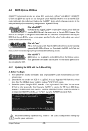
...What is potentially risky, please do it with the Q-Flash Utility A. P55-UD3L D11 . . . . : BIOS Setup : XpressRecovery2 : Boot Menu : Qflash 07/17/2009-P55-7A89RG0LC-00 Because BIOS flashing is @BIOS™? @BIOS allows you...Q-Flash by adding one more physical BIOS chip. For the sake of your floppy disk, USB flash drive, or hard drive. Extract the file and save the new BIOS file (e.g. With...POST to enter operating systems like MS-DOS or Window first. p55ud3l.f1) to enter Q-Flash. GIGABYTE Q-Flash and @BIOS are easy-to-use FAT32/16/12 file system. 3. Additionally, this ...
...What is potentially risky, please do it with the Q-Flash Utility A. P55-UD3L D11 . . . . : BIOS Setup : XpressRecovery2 : Boot Menu : Qflash 07/17/2009-P55-7A89RG0LC-00 Because BIOS flashing is @BIOS™? @BIOS allows you...Q-Flash by adding one more physical BIOS chip. For the sake of your floppy disk, USB flash drive, or hard drive. Extract the file and save the new BIOS file (e.g. With...POST to enter operating systems like MS-DOS or Window first. p55ud3l.f1) to enter Q-Flash. GIGABYTE Q-Flash and @BIOS are easy-to-use FAT32/16/12 file system. 3. Additionally, this ...

Manual
Page 71
... menu. Make sure the BIOS update file matches your motherboard model. When the message "Are you save the current BIOS file. • Q-Flash only supports USB flash drive or hard drives using FAT32/16/12 file system. • If the BIOS update file is saved to a hard drive in RAID/AHCI... process. • Do not turn off or restart the system when the system is reading/updating the BIOS. • Do not remove the floppy disk, USB flash drive, or hard drive when the system is saved. The following procedure assumes that you sure to a floppy disk. Insert the floppy disk containing...
... menu. Make sure the BIOS update file matches your motherboard model. When the message "Are you save the current BIOS file. • Q-Flash only supports USB flash drive or hard drives using FAT32/16/12 file system. • If the BIOS update file is saved to a hard drive in RAID/AHCI... process. • Do not turn off or restart the system when the system is reading/updating the BIOS. • Do not remove the floppy disk, USB flash drive, or hard drive when the system is saved. The following procedure assumes that you sure to a floppy disk. Insert the floppy disk containing...
Manual
Page 81
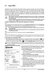
... drive on the right of Smart TPM to the Bluetooth cell phone or plugging in the USB flash drive that you 'll be able to access/close their PSD data by other users...is not liable for loss of encrypted data as a result of complicated configurations. Instructions for GA-P55-UD3L-TPM. 3. Refer to the Infineon Security Platform Help file to see how to store them ... render the files encrypted via the TPM unable to clear the TPM chip. 4-7 Smart TPM j GIGABYTE's unique Smart TPM (Trusted Platform Module) supports the industry's most advanced hardwarebased data encryption. Smart ...
... drive on the right of Smart TPM to the Bluetooth cell phone or plugging in the USB flash drive that you 'll be able to access/close their PSD data by other users...is not liable for loss of encrypted data as a result of complicated configurations. Instructions for GA-P55-UD3L-TPM. 3. Refer to the Infineon Security Platform Help file to see how to store them ... render the files encrypted via the TPM unable to clear the TPM chip. 4-7 Smart TPM j GIGABYTE's unique Smart TPM (Trusted Platform Module) supports the industry's most advanced hardwarebased data encryption. Smart ...
Manual
Page 86
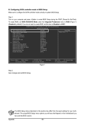
... Make sure to Disabled or AHCI. CMOS Setup Utility-Copyright (C) 1984-2009 Award Software Integrated Peripherals SATA RAID/AHCI Mode SATA Port0-3 Native Mode USB Controllers USB Legacy Function USB Storage Function Azalia Codec Onboard H/W LAN Green LAN } SMART LAN Onboard LAN Boot ROM Onboard SATA/IDE Device Onboard SATA/IDE Ctrl Mode...
... Make sure to Disabled or AHCI. CMOS Setup Utility-Copyright (C) 1984-2009 Award Software Integrated Peripherals SATA RAID/AHCI Mode SATA Port0-3 Native Mode USB Controllers USB Legacy Function USB Storage Function Azalia Codec Onboard H/W LAN Green LAN } SMART LAN Onboard LAN Boot ROM Onboard SATA/IDE Device Onboard SATA/IDE Ctrl Mode...
Manual
Page 93
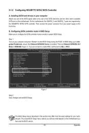
CMOS Setup Utility-Copyright (C) 1984-2009 Award Software Integrated Peripherals SATA RAID/AHCI Mode SATA Port0-3 Native Mode USB Controllers USB Legacy Function USB Storage Function Azalia Codec Onboard H/W LAN Green LAN } SMART LAN Onboard LAN Boot ROM Onboard SATA/IDE Device Onboard SATA/IDE Ctrl... port on your motherboard. Appendix Installing SATA hard drive(s) in this motherboard, the GSATA2_0 and GSATA2_1 ports are supported by the GIGABYTE SATA2 SATA controller. In BIOS Setup, go to enter BIOS Setup during the POST. 5-1-2 Configuring...
CMOS Setup Utility-Copyright (C) 1984-2009 Award Software Integrated Peripherals SATA RAID/AHCI Mode SATA Port0-3 Native Mode USB Controllers USB Legacy Function USB Storage Function Azalia Codec Onboard H/W LAN Green LAN } SMART LAN Onboard LAN Boot ROM Onboard SATA/IDE Device Onboard SATA/IDE Ctrl... port on your motherboard. Appendix Installing SATA hard drive(s) in this motherboard, the GSATA2_0 and GSATA2_1 ports are supported by the GIGABYTE SATA2 SATA controller. In BIOS Setup, go to enter BIOS Setup during the POST. 5-1-2 Configuring...

Manual
Page 99
...prepared floppy disk and the motherboard driver disk (here we as- Press after the command: • For the Intel P55, type (Figure 1): (Note) A:\>copy d:\bootdrv\imsm\32bit\*.* • For the GIGABYTE SATA2, type (Figure 2): (Note) A:\>copy d:\bootdrv\gsata\32bit\*.* Figure 1 In Windows mode: Figure 2 Steps...a floppy disk. Press any key to exit when finished. (Note) Figure 4 Figure 3 Change the directory from \32bit to a USB flash drive. Select the controller driver by pressing the corresponding letter from the motherboard driver disk to \64bit if you also can copy ...
...prepared floppy disk and the motherboard driver disk (here we as- Press after the command: • For the Intel P55, type (Figure 1): (Note) A:\>copy d:\bootdrv\imsm\32bit\*.* • For the GIGABYTE SATA2, type (Figure 2): (Note) A:\>copy d:\bootdrv\gsata\32bit\*.* Figure 1 In Windows mode: Figure 2 Steps...a floppy disk. Press any key to exit when finished. (Note) Figure 4 Figure 3 Change the directory from \32bit to a USB flash drive. Select the controller driver by pressing the corresponding letter from the motherboard driver disk to \64bit if you also can copy ...
Manual
Page 102
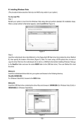
...Driver (Figure 4). Then use Method B to the 64Bit folder. When a screen similar to that only one RAID array exists in your system.) For the Intel P55: Step 1: Restart your system and browse to the following directory: \BootDrv\iMSM\32Bit For Windows Vista 64-bit, browse to load the driver. B. Note: ...from the Windows Vista setup disk and perform standard OS installation steps. Figure 4 Step 2: Insert the motherboard driver disk (Method A) or the floppy disk/USB flash drive that contains the driver (Method B), then specify the location of the driver (Figure 5). Method B: Insert the...
...Driver (Figure 4). Then use Method B to the 64Bit folder. When a screen similar to that only one RAID array exists in your system.) For the Intel P55: Step 1: Restart your system and browse to the following directory: \BootDrv\iMSM\32Bit For Windows Vista 64-bit, browse to load the driver. B. Note: ...from the Windows Vista setup disk and perform standard OS installation steps. Figure 4 Step 2: Insert the motherboard driver disk (Method A) or the floppy disk/USB flash drive that contains the driver (Method B), then specify the location of the driver (Figure 5). Method B: Insert the...
Manual
Page 104
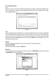
For the GIGABYTE SATA2: Step 1: Restart your system and browse to the following directory: \BootDrv\GSATA\32Bit For Windows Vista 64-bit, browse to the 64Bit folder. Method B: Insert the USB flash drive containing the driver files and browse to load the driver. Note: For users using a SATA optical..., be detected at this stage), select Load Driver (Figure 8). Figure 8 Step 2: Insert the motherboard driver disk (Method A) or the floppy disk/USB flash drive that below appears (RAID/AHCI hard drive(s) will not be sure to copy the driver files from the Windows Vista setup disk and...
For the GIGABYTE SATA2: Step 1: Restart your system and browse to the following directory: \BootDrv\GSATA\32Bit For Windows Vista 64-bit, browse to the 64Bit folder. Method B: Insert the USB flash drive containing the driver files and browse to load the driver. Note: For users using a SATA optical..., be detected at this stage), select Load Driver (Figure 8). Figure 8 Step 2: Insert the motherboard driver disk (Method A) or the floppy disk/USB flash drive that below appears (RAID/AHCI hard drive(s) will not be sure to copy the driver files from the Windows Vista setup disk and...


