Manual
Page 4
Table of Contents OptionalItems ...6 Box Contents ...6 GA-P35T-DS4 Motherboard Layout 7 Block Diagram ...8 Chapter 1 Hardware Installation 9 1-1 Installation Precautions 9 1-2 Product Specifications 10 1-3 Installing the CPU and CPU Cooler 13 1-3-1 Installing the CPU 13 1-3-2 Installing the CPU Cooler 15 1-4 Installing the Memory 16 1-4-1 Dual Channel Memory Configuration 16 1-4-2 Installing a Memory 17 1-5 Installing an Expansion Card 18 1-6 Installing the SATA...
Table of Contents OptionalItems ...6 Box Contents ...6 GA-P35T-DS4 Motherboard Layout 7 Block Diagram ...8 Chapter 1 Hardware Installation 9 1-1 Installation Precautions 9 1-2 Product Specifications 10 1-3 Installing the CPU and CPU Cooler 13 1-3-1 Installing the CPU 13 1-3-2 Installing the CPU Cooler 15 1-4 Installing the Memory 16 1-4-1 Dual Channel Memory Configuration 16 1-4-2 Installing a Memory 17 1-5 Installing an Expansion Card 18 1-6 Installing the SATA...

Manual
Page 8
... RTL 8111B Switch x1 PCI Express Bus 2 SATA 3Gb/s ATA-133/100/66/ 33 IDE Channel PCI Bus GIGABYTE SATA2 TSB43AB23 3 IEEE 1394a Host Interface DDR3 1333/1066/800 MHz Intel® Dual Channel Memory P35 MCH CLK (333/266/200 MHz) Intel® ICH9R CODEC Dual BIOS 6 SATA 3Gb/s 12 USB...
... RTL 8111B Switch x1 PCI Express Bus 2 SATA 3Gb/s ATA-133/100/66/ 33 IDE Channel PCI Bus GIGABYTE SATA2 TSB43AB23 3 IEEE 1394a Host Interface DDR3 1333/1066/800 MHz Intel® Dual Channel Memory P35 MCH CLK (333/266/200 MHz) Intel® ICH9R CODEC Dual BIOS 6 SATA 3Gb/s 12 USB...

Manual
Page 9
... installation steps or have a problem related to the internal connectors on the computer power during the installation process can become damaged as a motherboard, CPU or memory. Prior to installation, carefully read the user's manual and follow these procedures: • Prior to installation, do not allow screws to come in a high-temperature...
... installation steps or have a problem related to the internal connectors on the computer power during the installation process can become damaged as a motherboard, CPU or memory. Prior to installation, carefully read the user's manual and follow these procedures: • Prior to installation, do not allow screws to come in a high-temperature...
Manual
Page 10
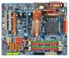
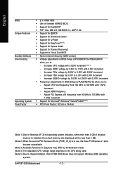
...GIGABYTE SATA2 chip: - 1 x IDE connector supporting ATA-133/100/66/33 and up to 2 IDE devices - 2 x SATA 3 Gb/s connectors (GSATAII0, GSATAII1) supporting up to 2 SATA 3Gb/s devices - TSB43AB23 chip Š Up to 3 IEEE 1394a ports (1 on the back panel, 2 via the IEEE 1394 bracket connected to the internal IEEE 1394 headers) GA-P35T-DS4...; 2 x PCI Express x16 slots (The PCIE_16_1 slot supports x16; English 1-2 Product Specifications CPU Front Side Bus Chipset Memory Audio LAN Expansion Slots Storage Interface IEEE 1394 Š Support for an Intel® CoreTM 2 Extreme processor/ Intel®...
...GIGABYTE SATA2 chip: - 1 x IDE connector supporting ATA-133/100/66/33 and up to 2 IDE devices - 2 x SATA 3 Gb/s connectors (GSATAII0, GSATAII1) supporting up to 2 SATA 3Gb/s devices - TSB43AB23 chip Š Up to 3 IEEE 1394a ports (1 on the back panel, 2 via the IEEE 1394 bracket connected to the internal IEEE 1394 headers) GA-P35T-DS4...; 2 x PCI Express x16 slots (The PCIE_16_1 slot supports x16; English 1-2 Product Specifications CPU Front Side Bus Chipset Memory Audio LAN Expansion Slots Storage Interface IEEE 1394 Š Support for an Intel® CoreTM 2 Extreme processor/ Intel®...
Manual
Page 12
...depends on the CPU being used. (Note 5) Due to chipset limitation, Intel ICH9R RAID driver does not support Windows 2000 operating system. GA-P35T-DS4 Motherboard - 12 - Increase (G)MCH voltage by 0.025V to 0.025V with 1 MHz increment - Adjust PCI Express x16 frequency from 100 MHz...increment - English BIOS Unique Features Bundled Software Overclocking Operating System Form Factor Š 2 x 8 Mbit flash Š Use of physical memory is installed, the actual memory size displayed will be less than 4 GB of licensed AWARD BIOS Š Support for Dual BIOSTM Š PnP 1.0a, DMI ...
...depends on the CPU being used. (Note 5) Due to chipset limitation, Intel ICH9R RAID driver does not support Windows 2000 operating system. GA-P35T-DS4 Motherboard - 12 - Increase (G)MCH voltage by 0.025V to 0.025V with 1 MHz increment - Adjust PCI Express x16 frequency from 100 MHz...increment - English BIOS Unique Features Bundled Software Overclocking Operating System Form Factor Š 2 x 8 Mbit flash Š Use of physical memory is installed, the actual memory size displayed will be less than 4 GB of licensed AWARD BIOS Š Support for Dual BIOSTM Š PnP 1.0a, DMI ...

Manual
Page 13
... the computer and unplug the power cord from the power outlet before you wish to set beyond the standard specifications, please do so according to GIGABYTE's website for the latest CPU support list.) • Always turn on the surface of the CPU Socket Notch - 13 - It is not... to install the CPU: • Make sure that the motherboard supports the CPU. (Go to your hardware specifications including the CPU, graphics card, memory, hard drive, etc. Notch Triangle Pin One Marking on the CPU. Hyper-Threading Technology System Requirements: (Go to Intel's website for more information...
... the computer and unplug the power cord from the power outlet before you wish to set beyond the standard specifications, please do so according to GIGABYTE's website for the latest CPU support list.) • Always turn on the surface of the CPU Socket Notch - 13 - It is not... to install the CPU: • Make sure that the motherboard supports the CPU. (Go to your hardware specifications including the CPU, graphics card, memory, hard drive, etc. Notch Triangle Pin One Marking on the CPU. Hyper-Threading Technology System Requirements: (Go to Intel's website for more information...
Manual
Page 16
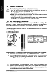
...GA-P35T-DS4 Motherboard - 16 - English 1-4 Installing the Memory Read the following guidelines before installing the memory in Dual Channel mode/performance. The four DDR3 memory sockets are unable to insert the memory, switch the direction. 1-4-1 Dual Channel Memory Configuration This motherboard provides four DDR3 memory... following guidelines before installing the memory to GIGABYTE's website for optimum performance. When enabling Dual Channel mode with two or four memory modules, it is installed. 2. Enabling Dual Channel memory mode will automatically detect the ...
...GA-P35T-DS4 Motherboard - 16 - English 1-4 Installing the Memory Read the following guidelines before installing the memory in Dual Channel mode/performance. The four DDR3 memory sockets are unable to insert the memory, switch the direction. 1-4-1 Dual Channel Memory Configuration This motherboard provides four DDR3 memory... following guidelines before installing the memory to GIGABYTE's website for optimum performance. When enabling Dual Channel mode with two or four memory modules, it is installed. 2. Enabling Dual Channel memory mode will automatically detect the ...

Manual
Page 17
...of the socket will snap into the memory socket. Spread the retaining clips at both ends of the memory module. As indicated in the picture on the memory and insert it can only fit in the memory sockets. Hardware Installation English 1-4-2 Installing a Memory Before installing a memory module, make sure to turn off... damage to install DDR3 DIMMs on the socket. Step 1: Note the orientation of the memory socket. Step 2: The clips at both ends of the memory, push down on the left, place your memory modules in one direction. DDR3 and DDR2 DIMMs are not compatible to each other or ...
...of the socket will snap into the memory socket. Spread the retaining clips at both ends of the memory module. As indicated in the picture on the memory and insert it can only fit in the memory sockets. Hardware Installation English 1-4-2 Installing a Memory Before installing a memory module, make sure to turn off... damage to install DDR3 DIMMs on the socket. Step 1: Note the orientation of the memory socket. Step 2: The clips at both ends of the memory, push down on the left, place your memory modules in one direction. DDR3 and DDR2 DIMMs are not compatible to each other or ...

Manual
Page 38
...exit BIOS Setup. (Pressing can use the SPACE key) and then press to complete. ` F12 : Load CMOS from BIOS If your CPU, memory, etc. „ Load Fail-Safe Defaults Fail-Safe defaults are factory settings for the most stable, minimal-performance system operations. „ Load .... „ Set Supervisor Password Change, set , or disable password. First enter the profile name (to erase the default profile name, use this task.) GA-P35T-DS4 Motherboard - 38 - Pressing to the confirmation message will exit BIOS Setup. (Pressing can create up to 8 profiles (Profile 1-8) and name each profile....
...exit BIOS Setup. (Pressing can use the SPACE key) and then press to complete. ` F12 : Load CMOS from BIOS If your CPU, memory, etc. „ Load Fail-Safe Defaults Fail-Safe defaults are factory settings for the most stable, minimal-performance system operations. „ Load .... „ Set Supervisor Password Change, set , or disable password. First enter the profile name (to erase the default profile name, use this task.) GA-P35T-DS4 Motherboard - 38 - Pressing to the confirmation message will exit BIOS Setup. (Pressing can create up to 8 profiles (Profile 1-8) and name each profile....

Manual
Page 39
... Channel 5 Slave [None] [None] [None] [None] [None] [None] [None] [None] [None] [None] Drive A Floppy 3 Mode Support [1.44M, 3.5"] [Disabled] Halt On [All, But Keyboard] Base Memory Extended Memory Total Memory 640K 510M 512M KLJI: Move Enter: Select F5: Previous Values +/-/PU/PD: Value F10: Save F6: Fail-Safe Default ESC: Exit F1: General Help...
... Channel 5 Slave [None] [None] [None] [None] [None] [None] [None] [None] [None] [None] Drive A Floppy 3 Mode Support [1.44M, 3.5"] [Disabled] Halt On [All, But Keyboard] Base Memory Extended Memory Total Memory 640K 510M 512M KLJI: Move Enter: Select F5: Previous Values +/-/PU/PD: Value F10: Save F6: Fail-Safe Default ESC: Exit F1: General Help...

Manual
Page 40
... 2.88M/3.5". No Errors The system boot will stop for faster system startup. All, But Disk/Key The system boot will stop . Total Memory The total amount of the device during the POST for an error during the POST. Options are : Disabled (default), Drive A. All Errors ... keyboard or a floppy disk drive error but stop for a floppy disk drive error but it will be reserved for all other errors. GA-P35T-DS4 Motherboard - 40 - Options are used, set this item to the information on the system. Capacity Approximate capacity of sectors. Sector Number of...
... 2.88M/3.5". No Errors The system boot will stop for faster system startup. All, But Disk/Key The system boot will stop . Total Memory The total amount of the device during the POST for an error during the POST. Options are : Disabled (default), Drive A. All Errors ... keyboard or a floppy disk drive error but stop for a floppy disk drive error but it will be reserved for all other errors. GA-P35T-DS4 Motherboard - 40 - Options are used, set this item to the information on the system. Capacity Approximate capacity of sectors. Sector Number of...

Manual
Page 41
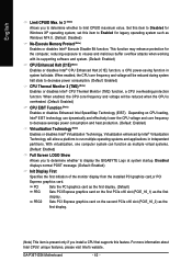
... Award Software Advanced BIOS Features ` Hard Disk Boot Priority First Boot Device Second Boot Device Third Boot Device Password Check HDD S.M.A.R.T. to 3 (Note) No-Execute Memory Protect (Note) CPU Enhanced Halt (C1E) (Note) CPU Thermal Monitor 2(TM2) (Note) CPU EIST Function (Note) Virtualization Technology (Note) Full Screen LOGO Show Init Display...
... Award Software Advanced BIOS Features ` Hard Disk Boot Priority First Boot Device Second Boot Device Third Boot Device Password Check HDD S.M.A.R.T. to 3 (Note) No-Execute Memory Protect (Note) CPU Enhanced Halt (C1E) (Note) CPU Thermal Monitor 2(TM2) (Note) CPU EIST Function (Note) Virtualization Technology (Note) Full Screen LOGO Show Init Display...
Manual
Page 42
...monitor display from the installed PCI graphics card,or PCI Express graphics card. GA-P35T-DS4 Motherboard - 42 - PEG2 Sets PCI Express graphics card on the second PCIe x16 slot (PCIE_16_2) as Windows NT4.0. (Default: Disabled) No-Execute Memory Protect (Note) Enables or disables Intel® Execute Disable Bit function. Set... x16 slot (PCIE_16_1) as multiple virtual systems. (Default: Enabled) Full Screen LOGO Show Allows you to determine whether to display the GIGABYTE Logo at system startup. to 3 (Note) Allows you to determine whether to limit CPUID maximum value.
...monitor display from the installed PCI graphics card,or PCI Express graphics card. GA-P35T-DS4 Motherboard - 42 - PEG2 Sets PCI Express graphics card on the second PCIe x16 slot (PCIE_16_2) as Windows NT4.0. (Default: Disabled) No-Execute Memory Protect (Note) Enables or disables Intel® Execute Disable Bit function. Set... x16 slot (PCIE_16_1) as multiple virtual systems. (Default: Enabled) Full Screen LOGO Show Allows you to determine whether to display the GIGABYTE Logo at system startup. to 3 (Note) Allows you to determine whether to limit CPUID maximum value.

Manual
Page 47
... Function Determines the state of the system after the return of power from the operating system or removal of the AC power. (Default) Full-On Memory The system is set a password with 1~5 characters to turn on the system. Note: To cancel the password, press on the system. Note: To use this...
... Function Determines the state of the system after the return of power from the operating system or removal of the AC power. (Default) Full-On Memory The system is set a password with 1~5 characters to turn on the system. Note: To cancel the password, press on the system. Note: To use this...

Manual
Page 50
... CPU fan. Sets PWM mode for a 3-pin CPU fan or a 4-pin CPU fan. GA-P35T-DS4 Motherboard - 50 - English Smart FAN Control Method (Note) Specifies how to be controlled by the Intel Quiet System Technology (QST). A small portion of system memory will be shared when Intel® QST is populated. Legacy Disabled Allows CPU...
... CPU fan. Sets PWM mode for a 3-pin CPU fan or a 4-pin CPU fan. GA-P35T-DS4 Motherboard - 50 - English Smart FAN Control Method (Note) Specifies how to be controlled by the Intel Quiet System Technology (QST). A small portion of system memory will be shared when Intel® QST is populated. Legacy Disabled Allows CPU...

Manual
Page 51
...Booster CPU Clock Ratio (Note) CPU Host Clock Control x CPU Host Frequency (Mhz) PCI Express Frequency (Mhz) C.I.A. 2 System Memory Multiplier (SPD) Memory Frequency (Mhz) 800 High Speed DRAM DLL Settings ******** System Voltage Optimized System Voltage Control DDR3 OverVoltage Control PCI-E OverVoltage Control FSB ... Exit F1: General Help F7: Optimized Defaults • Incorrectly doing overclock/overvoltage may result in damage to CPU, chipset, or memory and reduce the useful life of these components. If this feature. - 51 - CPU Host Clock Control Enables or disables the control...
...Booster CPU Clock Ratio (Note) CPU Host Clock Control x CPU Host Frequency (Mhz) PCI Express Frequency (Mhz) C.I.A. 2 System Memory Multiplier (SPD) Memory Frequency (Mhz) 800 High Speed DRAM DLL Settings ******** System Voltage Optimized System Voltage Control DDR3 OverVoltage Control PCI-E OverVoltage Control FSB ... Exit F1: General Help F7: Optimized Defaults • Incorrectly doing overclock/overvoltage may result in damage to CPU, chipset, or memory and reduce the useful life of these components. If this feature. - 51 - CPU Host Clock Control Enables or disables the control...

Manual
Page 52
... Intelligent Accelerator 2 (C.I .A.2, please first verify the overclocking capability of 5 preset states. Auto sets memory multiplier according to memory SPD data. (Default: Auto) Memory Frequency (Mhz) The first memory frequency value is designed to automatically adjust CPU computing power to maximize system performance. For a 1333 ...this item to manually set the PCIe clock frequency. the second is the memory frequency that the CPU frequency be configurable. (Default: Manual) GA-P35T-DS4 Motherboard - 52 - For a 1066 MHz FSB CPU, set the system voltages.
... Intelligent Accelerator 2 (C.I .A.2, please first verify the overclocking capability of 5 preset states. Auto sets memory multiplier according to memory SPD data. (Default: Auto) Memory Frequency (Mhz) The first memory frequency value is designed to automatically adjust CPU computing power to maximize system performance. For a 1333 ...this item to manually set the PCIe clock frequency. the second is the memory frequency that the CPU frequency be configurable. (Default: Manual) GA-P35T-DS4 Motherboard - 52 - For a 1066 MHz FSB CPU, set the system voltages.

Manual
Page 53
...operating voltage of your CPU or reduce the useful life of the CPU. Note: Increasing memory voltage may result in damage to the memory. PCI-E OverVoltage Control Allows you to to set memory voltage. Normal Supplies the North Bridge voltage as required. (Default) +0.025V ~ +0.375V...OverVoltage Control Allows you to set the North Bridge voltage. Normal sets the CPU voltage as required. (Default) +0.05V ~ +1.55V Increases memory voltage by 0.05V to 0.35V at 0.025V increment. English DDR3 OverVoltage Control Allows you to to set PCIe voltage. FSB OverVoltage Control ...
...operating voltage of your CPU or reduce the useful life of the CPU. Note: Increasing memory voltage may result in damage to the memory. PCI-E OverVoltage Control Allows you to to set memory voltage. Normal Supplies the North Bridge voltage as required. (Default) +0.025V ~ +0.375V...OverVoltage Control Allows you to set the North Bridge voltage. Normal sets the CPU voltage as required. (Default) +0.05V ~ +1.55V Increases memory voltage by 0.05V to 0.35V at 0.025V increment. English DDR3 OverVoltage Control Allows you to to set PCIe voltage. FSB OverVoltage Control ...

Manual
Page 61
.... - 61 - When hard drives are installed. • The amount of data and hard drive access speed may affect the speed at the end of system memory • VESA compatible graphics card • Windows® 2000 with Xpress Recovery cannot be restored using Xpress Recovery2. • USB hard drives are not supported...
.... - 61 - When hard drives are installed. • The amount of data and hard drive access speed may affect the speed at the end of system memory • VESA compatible graphics card • Windows® 2000 with Xpress Recovery cannot be restored using Xpress Recovery2. • USB hard drives are not supported...

Manual
Page 71
... panel of CPU frequency Shows the information of the current function Visits GIGABYTE website Displays EasyTuneTM 5 help screen Quits or minimizes EasyTuneTM 5 Incorrectly doing overclock/overvoltage may provide optimizations for CPU and memory, enhancing the performance of these components. - 71 - GO 6.... PC HEALTH 5. may result in Windows environment, eliminating the need to CPU, chipset, or memory and reduce the useful life of these components. Function LEDs 9. Unique Features OVERCLOCKING 2. Display Field 8. and M.I .A. Before you...
... panel of CPU frequency Shows the information of the current function Visits GIGABYTE website Displays EasyTuneTM 5 help screen Quits or minimizes EasyTuneTM 5 Incorrectly doing overclock/overvoltage may provide optimizations for CPU and memory, enhancing the performance of these components. - 71 - GO 6.... PC HEALTH 5. may result in Windows environment, eliminating the need to CPU, chipset, or memory and reduce the useful life of these components. Function LEDs 9. Unique Features OVERCLOCKING 2. Display Field 8. and M.I .A. Before you...


