
Manual
Page 1
GA-P35T-DS3P LGA775 socket motherboard for Intel® CoreTM processor family/ Intel® Pentium® processor family/Intel® Celeron® processor family User's Manual Rev. 1001 12ME-P35TDS3P-1001R * The WEEE marking on the product indicates this product must not be disposed of with user's other household waste and must be handed over to a designated collection point for the recycling of waste electrical and electronic equipment!! * The WEEE marking applies only in European Union's member states.
GA-P35T-DS3P LGA775 socket motherboard for Intel® CoreTM processor family/ Intel® Pentium® processor family/Intel® Celeron® processor family User's Manual Rev. 1001 12ME-P35TDS3P-1001R * The WEEE marking on the product indicates this product must not be disposed of with user's other household waste and must be handed over to a designated collection point for the recycling of waste electrical and electronic equipment!! * The WEEE marking applies only in European Union's member states.

Manual
Page 3
...information, check on our website at: http://www.gigabyte.com.tw Identifying Your Motherboard Revision The revision number on our website. sive global distributor of this manual may be made by GIGABYTE without GIGABYTE's prior written permission. Documentation Classifications In order to... or download the information on/from the Support\Motherboard\Technology Guide page on your motherboard revision before updating motherboard BIOS, drivers, or when looking for technical information. The trademarks mentioned in the use GIGABYTE's unique features, read the User's Manual. ...
...information, check on our website at: http://www.gigabyte.com.tw Identifying Your Motherboard Revision The revision number on our website. sive global distributor of this manual may be made by GIGABYTE without GIGABYTE's prior written permission. Documentation Classifications In order to... or download the information on/from the Support\Motherboard\Technology Guide page on your motherboard revision before updating motherboard BIOS, drivers, or when looking for technical information. The trademarks mentioned in the use GIGABYTE's unique features, read the User's Manual. ...

Manual
Page 4
Table of Contents OptionalItems ...6 Box Contents ...6 GA-P35T-DS3P Motherboard Layout 7 Block Diagram ...8 Chapter 1 Hardware Installation 9 1-1 Installation Precautions 9 1-2 Product Specifications 10 1-3 Installing the CPU and CPU Cooler 13 1-3-1 Installing the CPU 13 1-3-2 Installing the CPU ...
Table of Contents OptionalItems ...6 Box Contents ...6 GA-P35T-DS3P Motherboard Layout 7 Block Diagram ...8 Chapter 1 Hardware Installation 9 1-1 Installation Precautions 9 1-2 Product Specifications 10 1-3 Installing the CPU and CPU Cooler 13 1-3-1 Installing the CPU 13 1-3-2 Installing the CPU ...
Manual
Page 6
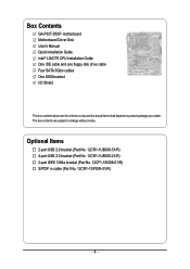
... (Part No. 12CR1-1SPDIN-01/R) - 6 - The box contents are for reference only and the actual items shall depend on product package you obtain. Box Contents GA-P35T-DS3P motherboard Motherboard Driver Disk User's Manual Quick Installation Guide Intel® LGA775 CPU Installation Guide One IDE cable and one floppy disk drive cable Four SATA 3Gb...
... (Part No. 12CR1-1SPDIN-01/R) - 6 - The box contents are for reference only and the actual items shall depend on product package you obtain. Box Contents GA-P35T-DS3P motherboard Motherboard Driver Disk User's Manual Quick Installation Guide Intel® LGA775 CPU Installation Guide One IDE cable and one floppy disk drive cable Four SATA 3Gb...

Manual
Page 7
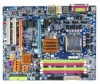
GA-P35T-DS3P Motherboard Layout KB_MS SYS_FAN1 COAXIAL OPTICAL ATX_12V_2X LGA775 PWR_FAN PCIE_12V COM LPT 1394 GA-P35T-DS3P ATX USB LAN USB CPU_FAN AUDIO Intel® P35 F_AUDIO PCIE_1 FDD RTL8111B PCIE_16_1 NB_FAN DDRIII1 DDRIII2 DDRIII3 DDRIII4 PCIE_2 BP_BIOS MAIN_BIOS CODEC PCIE_3 PCIE_16_2 CD_IN BATTERY CLR_CMOS Intel® ICH9R SATAII0 SATAII1 SATAII4 SATAII2 F_USB4 F_USB3 F_USB2 PCI1 IT8718 PCI2 SPDIF_IN SYS_FAN2 TSB43AB23 CI F1_1394 F_USB1 F2_1394 GSATAII0 SATAII5 SATAII3 GIGABYTE SATA2 IDE F_PANEL GSATAII1 PWR_LED - 7 -
GA-P35T-DS3P Motherboard Layout KB_MS SYS_FAN1 COAXIAL OPTICAL ATX_12V_2X LGA775 PWR_FAN PCIE_12V COM LPT 1394 GA-P35T-DS3P ATX USB LAN USB CPU_FAN AUDIO Intel® P35 F_AUDIO PCIE_1 FDD RTL8111B PCIE_16_1 NB_FAN DDRIII1 DDRIII2 DDRIII3 DDRIII4 PCIE_2 BP_BIOS MAIN_BIOS CODEC PCIE_3 PCIE_16_2 CD_IN BATTERY CLR_CMOS Intel® ICH9R SATAII0 SATAII1 SATAII4 SATAII2 F_USB4 F_USB3 F_USB2 PCI1 IT8718 PCI2 SPDIF_IN SYS_FAN2 TSB43AB23 CI F1_1394 F_USB1 F2_1394 GSATAII0 SATAII5 SATAII3 GIGABYTE SATA2 IDE F_PANEL GSATAII1 PWR_LED - 7 -

Manual
Page 9
..., please verify that all cables and power connectors of your hardware components are connected. • To prevent damage to the motherboard, do not have an ESD wrist strap, keep your dealer. These stickers are required for warranty validation. • Always ...of the product, please consult a certified computer technician. - 9 - Hardware Installation English Chapter 1 Hardware Installation 1-1 Installation Precautions The motherboard contains numerous delicate electronic circuits and components which can lead to damage to system components as well as physical harm to the user. &#...
..., please verify that all cables and power connectors of your hardware components are connected. • To prevent damage to the motherboard, do not have an ESD wrist strap, keep your dealer. These stickers are required for warranty validation. • Always ...of the product, please consult a certified computer technician. - 9 - Hardware Installation English Chapter 1 Hardware Installation 1-1 Installation Precautions The motherboard contains numerous delicate electronic circuits and components which can lead to damage to system components as well as physical harm to the user. &#...

Manual
Page 10
...1066/800 MHz memory modules (Go to the internal IEEE 1394 headers) GA-P35T-DS3P Motherboard - 10 - TSB43AB23 chip Š Up to 3 IEEE 1394a ports (1 on the back panel, 2 via the IEEE 1394 bracket connected to GIGABYTE's website for the latest memory support list.) Š Realtek ALC889A codec...® 4 processor Extreme Edition/Intel® Pentium® 4 processor/ Intel® Celeron® D processor in the LGA 775 package (Go to GIGABYTE's website for the latest CPU support list.) Š Support for Intel® Hyper-Threading Technology Š L2 cache varies with the PCIE_16_2 slot) (...
...1066/800 MHz memory modules (Go to the internal IEEE 1394 headers) GA-P35T-DS3P Motherboard - 10 - TSB43AB23 chip Š Up to 3 IEEE 1394a ports (1 on the back panel, 2 via the IEEE 1394 bracket connected to GIGABYTE's website for the latest memory support list.) Š Realtek ALC889A codec...® 4 processor Extreme Edition/Intel® Pentium® 4 processor/ Intel® Celeron® D processor in the LGA 775 package (Go to GIGABYTE's website for the latest CPU support list.) Š Support for Intel® Hyper-Threading Technology Š L2 cache varies with the PCIE_16_2 slot) (...

Manual
Page 12
GA-P35T-DS3P Motherboard - 12 - English BIOS Unique Features Bundled Software Operating System Form Factor Š 2 x 8 Mbit flash Š Use of licensed AWARD BIOS Š Support for Dual BIOSTM &#... second PCI Express x16 slot (PCIE_16_2) is in use, the three PCI Express x1 slots become unavailable. (Note 3) Available functions in Easytune may differ by motherboard model. (Note 4) Due to chipset limitation, Intel ICH9R RAID driver does not support Windows 2000 operating system.
GA-P35T-DS3P Motherboard - 12 - English BIOS Unique Features Bundled Software Operating System Form Factor Š 2 x 8 Mbit flash Š Use of licensed AWARD BIOS Š Support for Dual BIOSTM &#... second PCI Express x16 slot (PCIE_16_2) is in use, the three PCI Express x1 slots become unavailable. (Note 3) Available functions in Easytune may differ by motherboard model. (Note 4) Due to chipset limitation, Intel ICH9R RAID driver does not support Windows 2000 operating system.

Manual
Page 13
...and unplug the power cord from the power outlet before you begin to install the CPU: • Make sure that the motherboard supports the CPU. (Go to GIGABYTE's website for the latest CPU support list.) • Always turn on the CPU Hardware Installation Locate the alignment keys on ...the motherboard CPU socket and the notches on enabling the HT Technology.) 1-3-1 Installing the CPU A. English 1-3 Installing the CPU and CPU Cooler ...
...and unplug the power cord from the power outlet before you begin to install the CPU: • Make sure that the motherboard supports the CPU. (Go to GIGABYTE's website for the latest CPU support list.) • Always turn on the CPU Hardware Installation Locate the alignment keys on ...the motherboard CPU socket and the notches on enabling the HT Technology.) 1-3-1 Installing the CPU A. English 1-3 Installing the CPU and CPU Cooler ...

Manual
Page 14
Step 2: Remove the protective socket cover. Step 3: Lift the metal load plate on the CPU socket. GA-P35T-DS3P Motherboard - 14 - Step 4: Hold the CPU with the socket alignment keys) and gently insert the CPU into position. Before installing the CPU, make sure to turn ... CPU into its locked position. Step 5: Once the CPU is properly inserted, replace the load plate and push the CPU socket lever back into the motherboard CPU socket. English B. CPU Socket Lever Step 1: Completely raise the CPU socket lever. Follow the steps below to the CPU. Align the CPU pin one...
Step 2: Remove the protective socket cover. Step 3: Lift the metal load plate on the CPU socket. GA-P35T-DS3P Motherboard - 14 - Step 4: Hold the CPU with the socket alignment keys) and gently insert the CPU into position. Before installing the CPU, make sure to turn ... CPU into its locked position. Step 5: Once the CPU is properly inserted, replace the load plate and push the CPU socket lever back into the motherboard CPU socket. English B. CPU Socket Lever Step 1: Completely raise the CPU socket lever. Follow the steps below to the CPU. Align the CPU pin one...

Manual
Page 15
.... If the push pin is inserted as the example cooler.) Step 1: Apply an even and thin layer of thermal grease on the surface of the motherboard. Step 6: Finally, attach the power connector of arrow is to remove the cooler, on the contrary, is to install.) Step 3: Place the cooler atop the... CPU, aligning the four push pins through the pin holes on the motherboard. Use extreme care when removing the CPU cooler because the thermal grease/tape between the CPU cooler and CPU may damage the CPU. - 15 - Direction...
.... If the push pin is inserted as the example cooler.) Step 1: Apply an even and thin layer of thermal grease on the surface of the motherboard. Step 6: Finally, attach the power connector of arrow is to remove the cooler, on the contrary, is to install.) Step 3: Place the cooler atop the... CPU, aligning the four push pins through the pin holes on the motherboard. Use extreme care when removing the CPU cooler because the thermal grease/tape between the CPU cooler and CPU may damage the CPU. - 15 - Direction...

Manual
Page 16
... with two or four memory modules, it is recommended that memory of different capacity and chips are unable to be enabled if only one direction. GA-P35T-DS3P Motherboard - 16 - DS/SS - - When memory modules of the same capacity, brand, speed, and chips be used and installed in the same colored...is installed, the BIOS will double the original memory bandwidth. Four Modules DS/SS DS/SS DS/SS DDRIII4 - If you begin to GIGABYTE's website for optimum performance. It is recommended that memory of the memory. The four DDR3 memory sockets are divided into two channels and each...
... with two or four memory modules, it is recommended that memory of different capacity and chips are unable to be enabled if only one direction. GA-P35T-DS3P Motherboard - 16 - DS/SS - - When memory modules of the same capacity, brand, speed, and chips be used and installed in the same colored...is installed, the BIOS will double the original memory bandwidth. Four Modules DS/SS DS/SS DS/SS DDRIII4 - If you begin to GIGABYTE's website for optimum performance. It is recommended that memory of the memory. The four DDR3 memory sockets are divided into two channels and each...

Manual
Page 17
... the memory module. DDR3 and DDR2 DIMMs are not compatible to each other or DDR DIMMs. Be sure to correctly install your fingers on this motherboard. Hardware Installation English 1-4-2 Installing a Memory Before installing a memory module, make sure to turn off the computer and unplug the power cord from the power outlet...
... the memory module. DDR3 and DDR2 DIMMs are not compatible to each other or DDR DIMMs. Be sure to correctly install your fingers on this motherboard. Hardware Installation English 1-4-2 Installing a Memory Before installing a memory module, make sure to turn off the computer and unplug the power cord from the power outlet...

Manual
Page 18
... to make any required BIOS changes for your expansion card in the expansion slot. 1. Install the driver provided with a screw. 5. GA-P35T-DS3P Motherboard - 18 - English 1-5 Installing an Expansion Card Read the following guidelines before installing an expansion card to install an expansion card: •... Make sure the motherboard supports the expansion card. Turn on the card until it is fully seated in your computer. Make sure the small white-drawable...
... to make any required BIOS changes for your expansion card in the expansion slot. 1. Install the driver provided with a screw. 5. GA-P35T-DS3P Motherboard - 18 - English 1-5 Installing an Expansion Card Read the following guidelines before installing an expansion card to install an expansion card: •... Make sure the motherboard supports the expansion card. Turn on the card until it is fully seated in your computer. Make sure the small white-drawable...

Manual
Page 19
... at the end of the PCI Express x16 slot to release the card and then pull the card straight up from the slot. • The motherboard provides a PCIE_12V power connector, which can supply extra power to this connector. - 19 -
... at the end of the PCI Express x16 slot to release the card and then pull the card straight up from the slot. • The motherboard provides a PCIE_12V power connector, which can supply extra power to this connector. - 19 -

Manual
Page 20
... SATA device(s) to your system by expanding the internal SATA port(s) to the chassis back panel. • Turn off the power of the external enclosure. GA-P35T-DS3P Motherboard - 20 - English 1-6 Installing the SATA Bracket The SATA bracket allows you only need to connect the SATA signal cable. Step 2: Connect the SATA cable from... cable and SATA power cable to the SATA port on the bracket. Step 5: Connect the other ends of the cable from the bracket to your motherboard. Before connecting the SATA signal cable, make sure to the power connec-
... SATA device(s) to your system by expanding the internal SATA port(s) to the chassis back panel. • Turn off the power of the external enclosure. GA-P35T-DS3P Motherboard - 20 - English 1-6 Installing the SATA Bracket The SATA bracket allows you only need to connect the SATA signal cable. Step 2: Connect the SATA cable from... cable and SATA power cable to the SATA port on the bracket. Step 5: Connect the other ends of the cable from the bracket to your motherboard. Before connecting the SATA signal cable, make sure to the power connec-

Manual
Page 21
... and etc. Use this feature, ensure that your audio system provides an optical digital audio in connector. Do not rock it straight out from the motherboard. • When removing the cable, pull it side to side to prevent an electrical short inside the cable connector. - 21 - The following describes the states...
... and etc. Use this feature, ensure that your audio system provides an optical digital audio in connector. Do not rock it straight out from the motherboard. • When removing the cable, pull it side to side to prevent an electrical short inside the cable connector. - 21 - The following describes the states...

Manual
Page 22
... reconfigured to this jack. In addition to the default speakers settings, the ~ audio jacks can be connected to connect front speakers in a 4/5.1/7.1-channel audio configuration. GA-P35T-DS3P Motherboard - 22 - Mic In Jack (Pink) The default Mic in jack. Use this audio jack for line in devices such as an optical drive, walkman, etc...
... reconfigured to this jack. In addition to the default speakers settings, the ~ audio jacks can be connected to connect front speakers in a 4/5.1/7.1-channel audio configuration. GA-P35T-DS3P Motherboard - 22 - Mic In Jack (Pink) The default Mic in jack. Use this audio jack for line in devices such as an optical drive, walkman, etc...

Manual
Page 23
..., make sure your devices are compliant with the connectors you wish to connect. • Before installing the devices, be sure to the connector on the motherboard. - 23 -
..., make sure your devices are compliant with the connectors you wish to connect. • Before installing the devices, be sure to the connector on the motherboard. - 23 -

Manual
Page 24
.../Off) GND GND GND -5V +5V +5V +5V (Only for 2x12 pin ATX) GND (Only for 2x4 pin 12V) 7 +12V 8 +12V 12 24 1 13 ATX GA-P35T-DS3P Motherboard ATX : Pin No. 1 2 3 4 5 6 7 8 9 10 11 12 Definition Pin No. 3.3V 13 3.3V 14 GND 15 +5V 16 GND 17 +5V 18 ... a power supply providing a 2x4 12V and a 2x12 power connector, remove the protective covers from the 12V power connector and the main power connector on the motherboard. If the 12V power connector is used (400W or greater). When using a power supply providing a 2x2 12V and a 2x10 power connector. 8 4 5 1 ...
.../Off) GND GND GND -5V +5V +5V +5V (Only for 2x12 pin ATX) GND (Only for 2x4 pin 12V) 7 +12V 8 +12V 12 24 1 13 ATX GA-P35T-DS3P Motherboard ATX : Pin No. 1 2 3 4 5 6 7 8 9 10 11 12 Definition Pin No. 3.3V 13 3.3V 14 GND 15 +5V 16 GND 17 +5V 18 ... a power supply providing a 2x4 12V and a 2x12 power connector, remove the protective covers from the 12V power connector and the main power connector on the motherboard. If the 12V power connector is used (400W or greater). When using a power supply providing a 2x2 12V and a 2x10 power connector. 8 4 5 1 ...


