Manual
Page 1
GA-P35C-DS3R/ GA-P35C-DS3/ GA-P35C-S3 LGA775 socket motherboard for Intel® CoreTM processor family/ Intel® Pentium® processor family/Intel® Celeron® processor family User's Manual Rev. 2002 12ME-P35CDS3R-2002R * The WEEE marking on the product indicates this product must not be disposed of with user's other household waste and must be handed over to a designated collection point for the recycling of waste electrical and electronic equipment!! * The WEEE marking applies only in European Union's member states.
GA-P35C-DS3R/ GA-P35C-DS3/ GA-P35C-S3 LGA775 socket motherboard for Intel® CoreTM processor family/ Intel® Pentium® processor family/Intel® Celeron® processor family User's Manual Rev. 2002 12ME-P35CDS3R-2002R * The WEEE marking on the product indicates this product must not be disposed of with user's other household waste and must be handed over to a designated collection point for the recycling of waste electrical and electronic equipment!! * The WEEE marking applies only in European Union's member states.
Manual
Page 2
Motherboard GA-P35C-DS3R/GA-P35C-DS3/GA-P35C-S3 Jul. 26, 2007 Motherboard GA-P35C-DS3R/GA-P35C-DS3/ GA-P35C-S3 Jul. 26, 2007
Motherboard GA-P35C-DS3R/GA-P35C-DS3/GA-P35C-S3 Jul. 26, 2007 Motherboard GA-P35C-DS3R/GA-P35C-DS3/ GA-P35C-S3 Jul. 26, 2007
Manual
Page 3
...made by copyright laws and is exclusively licensed to use GIGABYTE's unique features, read or download the information on/from the Support\Motherboard\Technology Guide page on your motherboard revision before updating motherboard BIOS, drivers, or when looking for technical information. For... information, check on our website at: http://www.gigabyte.com.tw Identifying Your Motherboard Revision The revision number on our website. The trademarks mentioned in this manual is protected by GIGABYTE without GIGABYTE's prior written permission. Documentation Classifications In order to ...
...made by copyright laws and is exclusively licensed to use GIGABYTE's unique features, read or download the information on/from the Support\Motherboard\Technology Guide page on your motherboard revision before updating motherboard BIOS, drivers, or when looking for technical information. For... information, check on our website at: http://www.gigabyte.com.tw Identifying Your Motherboard Revision The revision number on our website. The trademarks mentioned in this manual is protected by GIGABYTE without GIGABYTE's prior written permission. Documentation Classifications In order to ...

Manual
Page 4
Table of Contents Box Contents ...6 OptionalItems ...6 GA-P35C-DS3R/DS3/S3 Motherboard Layout 7 Block Diagram ...8 Chapter 1 Hardware Installation 9 1-1 Installation Precautions 9 1-2 Product Specifications 10 1-3 Installing the CPU and CPU Cooler 13 1-3-1 Installing the CPU 13 1-3-2 Installing the CPU ...
Table of Contents Box Contents ...6 OptionalItems ...6 GA-P35C-DS3R/DS3/S3 Motherboard Layout 7 Block Diagram ...8 Chapter 1 Hardware Installation 9 1-1 Installation Precautions 9 1-2 Product Specifications 10 1-3 Installing the CPU and CPU Cooler 13 1-3-1 Installing the CPU 13 1-3-2 Installing the CPU ...
Manual
Page 6
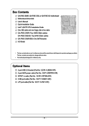
... in cable (Part No. 12CR1-1SPDIN-01R) COM port cable (Part No. 12CF1-1CM001-32R) LPT port cable (Part No. 12CF1-1LP001-01R) - 6 - Box Contents GA-P35C-DS3R, GA-P35C-DS3, or GA-P35C-S3 motherboard Motherboard driver disk User's Manual Quick Installation Guide Intel® LGA775 CPU Installation Guide One IDE cable and one floppy disk drive cable...
... in cable (Part No. 12CR1-1SPDIN-01R) COM port cable (Part No. 12CF1-1CM001-32R) LPT port cable (Part No. 12CF1-1LP001-01R) - 6 - Box Contents GA-P35C-DS3R, GA-P35C-DS3, or GA-P35C-S3 motherboard Motherboard driver disk User's Manual Quick Installation Guide Intel® LGA775 CPU Installation Guide One IDE cable and one floppy disk drive cable...

Manual
Page 7
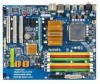
Only for GA-P35C-DS3R. GA-P35C-DS3R/DS3/S3 Motherboard Layout KB_MS ATX_12V CPU_FAN RCA SPDIF LGA775 ATX R_USB1 R_USB2 R_USB3 SYS_FAN2 GA-P35C-DS3R/DS3/S3 USB LAN F_AUDIO AUDIO SYS_FAN1 RTL8111B PCIE_3 PCIE_16 CODEC PCIE_1 PCIE_2 SPDIF_O PCI1 SPDIF_I PCI2 IT8718 ... DDRII1 FDD PWR_FAN Intel® ICH9R /ICH9 SATAII2 SATAII3 BAT GSATAII0 CLR_CMOS GSATAII1 GIGABYTE SATA2 / JMicron 368 BIOS SATAII0 SATAII1 SATAII4 SATAII5 IDE1 CI LPT F_USB2 F_USB1 PWR_LED F_PANEL Only for GA-P35C-S3. "*" Only the GA-P35C-DS3R/DS3 adopts All-Solid Capacitor design. - 7 - Only for...
Only for GA-P35C-DS3R. GA-P35C-DS3R/DS3/S3 Motherboard Layout KB_MS ATX_12V CPU_FAN RCA SPDIF LGA775 ATX R_USB1 R_USB2 R_USB3 SYS_FAN2 GA-P35C-DS3R/DS3/S3 USB LAN F_AUDIO AUDIO SYS_FAN1 RTL8111B PCIE_3 PCIE_16 CODEC PCIE_1 PCIE_2 SPDIF_O PCI1 SPDIF_I PCI2 IT8718 ... DDRII1 FDD PWR_FAN Intel® ICH9R /ICH9 SATAII2 SATAII3 BAT GSATAII0 CLR_CMOS GSATAII1 GIGABYTE SATA2 / JMicron 368 BIOS SATAII0 SATAII1 SATAII4 SATAII5 IDE1 CI LPT F_USB2 F_USB1 PWR_LED F_PANEL Only for GA-P35C-S3. "*" Only the GA-P35C-DS3R/DS3 adopts All-Solid Capacitor design. - 7 - Only for...
Manual
Page 9
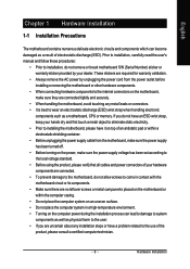
...required for warranty validation. • Always remove the AC power by your dealer. English Chapter 1 Hardware Installation 1-1 Installation Precautions The motherboard contains numerous delicate electronic circuits and components which can lead to damage to system components as well as physical harm to the user....ESD wrist strap, keep your hands dry and first touch a metal object to eliminate static electricity. • Prior to installing the motherboard, please have a problem related to the local voltage standard. • Before using the product, please verify that all cables and ...
...required for warranty validation. • Always remove the AC power by your dealer. English Chapter 1 Hardware Installation 1-1 Installation Precautions The motherboard contains numerous delicate electronic circuits and components which can lead to damage to system components as well as physical harm to the user....ESD wrist strap, keep your hands dry and first touch a metal object to eliminate static electricity. • Prior to installing the motherboard, please have a problem related to the local voltage standard. • Before using the product, please verify that all cables and ...
Manual
Page 10
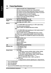
...-Solid Capacitor design. GA-P35C-DS3R/DS3/S3 Motherboard - 10 - Only for GA-P35C-S3. Support for SATA RAID 0, RAID 1, RAID 5, and RAID 10 Š iTE IT8718 chip: - 1 x floppy disk drive connector supporting up to 4 SATA 3Gb/s devices (Note 2) - Only for GA-P35C-DS3. Go to GIGABYTE's website for the latest...1333/1066/800 MHz memory modules DDR2: Š 4 x 1.8V DDR2 DIMM sockets supporting up to 1 floppy disk drive Only for GA-P35C-DS3R. English 1-2 Product Specifications CPU Front Side Bus Chipset Memory Audio LAN Expansion Slots Storage Interface Š Support for an Intel®...
...-Solid Capacitor design. GA-P35C-DS3R/DS3/S3 Motherboard - 10 - Only for GA-P35C-S3. Support for SATA RAID 0, RAID 1, RAID 5, and RAID 10 Š iTE IT8718 chip: - 1 x floppy disk drive connector supporting up to 4 SATA 3Gb/s devices (Note 2) - Only for GA-P35C-DS3. Go to GIGABYTE's website for the latest...1333/1066/800 MHz memory modules DDR2: Š 4 x 1.8V DDR2 DIMM sockets supporting up to 1 floppy disk drive Only for GA-P35C-DS3R. English 1-2 Product Specifications CPU Front Side Bus Chipset Memory Audio LAN Expansion Slots Storage Interface Š Support for an Intel®...
Manual
Page 12
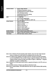
GA-P35C-DS3R/DS3/S3 Motherboard - 12 - English Hardware Monitor BIOS Unique Features Bundled Software Operating System Form Factor Š System voltage detection Š CPU/System temperature detection Š CPU/System/... 3) Whether the CPU fan speed control function is supported will depend on the CPU cooler you install. (Note 4) Available functions in Easytune may differ by motherboard model. (Note 5) Due to chipset limitation, Intel ICH9R RAID driver does not support Windows 2000 operating system.
GA-P35C-DS3R/DS3/S3 Motherboard - 12 - English Hardware Monitor BIOS Unique Features Bundled Software Operating System Form Factor Š System voltage detection Š CPU/System temperature detection Š CPU/System/... 3) Whether the CPU fan speed control function is supported will depend on the CPU cooler you install. (Note 4) Available functions in Easytune may differ by motherboard model. (Note 5) Due to chipset limitation, Intel ICH9R RAID driver does not support Windows 2000 operating system.
Manual
Page 13
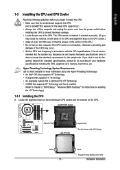
It is optimized for HT Technology • A BIOS that the motherboard supports the CPU. (Go to GIGABYTE's website for the latest CPU support list.) • Always turn on enabling the HT Technology.) 1-3-1 Installing the CPU A. mended that the system bus frequency be ...: • Make sure that supports HT Technology and has it does not meet the standard requirements for the peripherals. Locate the alignment keys on the motherboard CPU socket and the notches on the CPU Hardware Installation LGA775 CPU Socket Alignment Key LGA 775 CPU Alignment Key Pin One Corner of the...
It is optimized for HT Technology • A BIOS that the motherboard supports the CPU. (Go to GIGABYTE's website for the latest CPU support list.) • Always turn on enabling the HT Technology.) 1-3-1 Installing the CPU A. mended that the system bus frequency be ...: • Make sure that supports HT Technology and has it does not meet the standard requirements for the peripherals. Locate the alignment keys on the motherboard CPU socket and the notches on the CPU Hardware Installation LGA775 CPU Socket Alignment Key LGA 775 CPU Alignment Key Pin One Corner of the...
Manual
Page 14
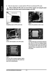
... prevent damage to correctly install the CPU into position. Step 4: Hold the CPU with the socket alignment keys) and gently insert the CPU into the motherboard CPU socket. Align the CPU pin one marking (triangle) with the pin one corner of the CPU socket (or you may align the CPU notches..., replace the load plate and push the CPU socket lever back into its locked position. CPU Socket Lever Step 1: Completely raise the CPU socket lever. GA-P35C-DS3R/DS3/S3 Motherboard - 14 - Step 2: Remove the protective socket cover. English B.
... prevent damage to correctly install the CPU into position. Step 4: Hold the CPU with the socket alignment keys) and gently insert the CPU into the motherboard CPU socket. Align the CPU pin one marking (triangle) with the pin one corner of the CPU socket (or you may align the CPU notches..., replace the load plate and push the CPU socket lever back into its locked position. CPU Socket Lever Step 1: Completely raise the CPU socket lever. GA-P35C-DS3R/DS3/S3 Motherboard - 14 - Step 2: Remove the protective socket cover. English B.
Manual
Page 15
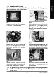
... 15 - Check that the Male and Female push pins are joined closely. (Refer to your CPU cooler installation manual for instructions on the motherboard. If the push pin is inserted as the example cooler.) Step 1: Apply an even and thin layer of thermal grease on the surface ...the back of the installed CPU. Hardware Installation English 1-3-2 Installing the CPU Cooler Follow the steps below to correctly install the CPU cooler on the motherboard. (The following procedure uses Intel® boxed cooler as the picture above, the installation is complete. Step 4: You should hear a "click"...
... 15 - Check that the Male and Female push pins are joined closely. (Refer to your CPU cooler installation manual for instructions on the motherboard. If the push pin is inserted as the example cooler.) Step 1: Apply an even and thin layer of thermal grease on the surface ...the back of the installed CPU. Hardware Installation English 1-3-2 Installing the CPU Cooler Follow the steps below to correctly install the CPU cooler on the motherboard. (The following procedure uses Intel® boxed cooler as the picture above, the installation is complete. Step 4: You should hear a "click"...
Manual
Page 16
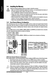
... Memory Mode will appear during the POST. Enabling Dual Channel memory mode will automatically detect the specifications and capacity of the memory. GA-P35C-DS3R/DS3/S3 Motherboard - 16 - If you begin to be installed in only one DDR2 memory module is installed. 2. Intel® Flex Memory ... DDR2 and DDR3 memory modules simultaneously is recommended that memory of the same capacity, brand, speed, and chips be used . (Go to GIGABYTE's website for optimum performance. The four DDR2 memory sockets (DDRII1, DDRII2, DDRII3, and DDRII4) are divided into two channels and each channel...
... Memory Mode will appear during the POST. Enabling Dual Channel memory mode will automatically detect the specifications and capacity of the memory. GA-P35C-DS3R/DS3/S3 Motherboard - 16 - If you begin to be installed in only one DDR2 memory module is installed. 2. Intel® Flex Memory ... DDR2 and DDR3 memory modules simultaneously is recommended that memory of the same capacity, brand, speed, and chips be used . (Go to GIGABYTE's website for optimum performance. The four DDR2 memory sockets (DDRII1, DDRII2, DDRII3, and DDRII4) are divided into two channels and each channel...

Manual
Page 17
... and unplug the power cord from the power outlet to prevent damage to each other or DDR DIMMs. Do not install DDR DIMMs on this motherboard. Step 1: Note the orientation of the socket will snap into the memory socket. Place the memory module on the socket. As indicated in the picture...
... and unplug the power cord from the power outlet to prevent damage to each other or DDR DIMMs. Do not install DDR DIMMs on this motherboard. Step 1: Note the orientation of the socket will snap into the memory socket. Place the memory module on the socket. As indicated in the picture...
Manual
Page 18
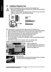
... and unplug the power cord from the power outlet before you begin to install an expansion card: • Make sure the motherboard supports the expansion card. Install the driver provided with the slot, and press down on the card are completely inserted into the...slot to the chassis back panel with your expansion card in your computer. Align the card with the expansion card in the expansion slot. 1. GA-P35C-DS3R/DS3/S3 Motherboard - 18 - Example: Installing and Removing a PCI Express x16 Graphics Card: • Installing a Graphics Card: Gently insert the graphics card ...
... and unplug the power cord from the power outlet before you begin to install an expansion card: • Make sure the motherboard supports the expansion card. Install the driver provided with the slot, and press down on the card are completely inserted into the...slot to the chassis back panel with your expansion card in your computer. Align the card with the expansion card in the expansion slot. 1. GA-P35C-DS3R/DS3/S3 Motherboard - 18 - Example: Installing and Removing a PCI Express x16 Graphics Card: • Installing a Graphics Card: Gently insert the graphics card ...

Manual
Page 19
... the chassis back panel with a screw. connector on the bracket. Connect the other ends of the SATA signal cable and SATA power cable to your motherboard. English 1-6 Installing the SATA Bracket The SATA bracket allows you only need to connect the SATA signal cable. Then attach the SATA power cable to...
... the chassis back panel with a screw. connector on the bracket. Connect the other ends of the SATA signal cable and SATA power cable to your motherboard. English 1-6 Installing the SATA Bracket The SATA bracket allows you only need to connect the SATA signal cable. Then attach the SATA power cable to...

Manual
Page 20
... side to a back panel connector, first remove the cable from your device and then remove it from the motherboard. • When removing the cable, pull it straight out from the connector. GA-P35C-DS3R/DS3/S3 Motherboard - 20 - USB Port The USB port supports the USB 2.0/1.1 specification. Use this feature, ensure that your audio system...
... side to a back panel connector, first remove the cable from your device and then remove it from the motherboard. • When removing the cable, pull it straight out from the connector. GA-P35C-DS3R/DS3/S3 Motherboard - 20 - USB Port The USB port supports the USB 2.0/1.1 specification. Use this feature, ensure that your audio system...
Manual
Page 22
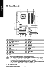
Only for GA-P35C-DS3R. GA-P35C-DS3R/DS3/S3 Motherboard - 22 - Unplug the power cord from the power outlet to prevent damage to the devices. • After installing the device and before connecting external devices: &#..., make sure your devices are compliant with the connectors you wish to connect. • Before installing the devices, be sure to the connector on the motherboard.
Only for GA-P35C-DS3R. GA-P35C-DS3R/DS3/S3 Motherboard - 22 - Unplug the power cord from the power outlet to prevent damage to the devices. • After installing the device and before connecting external devices: &#..., make sure your devices are compliant with the connectors you wish to connect. • Before installing the devices, be sure to the connector on the motherboard.

Manual
Page 23
...supply cable into pins under the protective cover when using a 2x12 power supply, remove the protective cover from the main power connector on the motherboard. English 1/2) ATX_12V/ATX (2x2 12V Power Connector and 2x12 Main Power Connector) With the use of the power connector, the power supply... are properly installed. Before connecting the power connector, first make sure the power supply is turned off and all the components on the motherboard. If a power supply is compatible with power supplies with 2x10 power connectors. The 12V power connector mainly supplies power to the power ...
...supply cable into pins under the protective cover when using a 2x12 power supply, remove the protective cover from the main power connector on the motherboard. English 1/2) ATX_12V/ATX (2x2 12V Power Connector and 2x12 Main Power Connector) With the use of the power connector, the power supply... are properly installed. Before connecting the power connector, first make sure the power supply is turned off and all the components on the motherboard. If a power supply is compatible with power supplies with 2x10 power connectors. The 12V power connector mainly supplies power to the power ...
Manual
Page 24
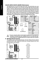
Do not place a jumper cap on the connector. 34 33 GA-P35C-DS3R/DS3/S3 Motherboard - 24 - 2 1 Before connecting a floppy disk drive, locate the foolproof groove on the headers. 6) FDD (Floppy Disk Drive Connector) This connector is the ground .... The types of a CPU fan with color-coded power connector wires. CPU_FAN (For PCB rev. 2.0): Pin No. English 3/4/5) CPU_FAN/SYS_FAN1/SYS_FAN2/PWR_FAN (Fan Headers) The motherboard has a 4-pin CPU fan header (CPU_FAN), a 3-pin (SYS_FAN1) and a 4-pin (SYS_FAN2) system fan headers, and a 3-pin power fan header (PWR_FAN). The black...
Do not place a jumper cap on the connector. 34 33 GA-P35C-DS3R/DS3/S3 Motherboard - 24 - 2 1 Before connecting a floppy disk drive, locate the foolproof groove on the headers. 6) FDD (Floppy Disk Drive Connector) This connector is the ground .... The types of a CPU fan with color-coded power connector wires. CPU_FAN (For PCB rev. 2.0): Pin No. English 3/4/5) CPU_FAN/SYS_FAN1/SYS_FAN2/PWR_FAN (Fan Headers) The motherboard has a 4-pin CPU fan header (CPU_FAN), a 3-pin (SYS_FAN1) and a 4-pin (SYS_FAN2) system fan headers, and a 3-pin power fan header (PWR_FAN). The black...


