Manual
Page 3
... page on your motherboard revision before updating motherboard BIOS, drivers, or when looking for technical information. For example, "REV: 1.0" means the revision of the motherboard is the property of GIGABYTE branded motherboards. For product-related information, check ...translated, transmitted, or published in this : "REV: X.X." Documentation Classifications In order to GIGABYTE UNITED INC. by GIGABYTE without GIGABYTE's prior written permission. sive global distributor of GIGABYTE. is exclusively licensed to assist in this manual is protected by copyright laws and is ...
... page on your motherboard revision before updating motherboard BIOS, drivers, or when looking for technical information. For example, "REV: 1.0" means the revision of the motherboard is the property of GIGABYTE branded motherboards. For product-related information, check ...translated, transmitted, or published in this : "REV: X.X." Documentation Classifications In order to GIGABYTE UNITED INC. by GIGABYTE without GIGABYTE's prior written permission. sive global distributor of GIGABYTE. is exclusively licensed to assist in this manual is protected by copyright laws and is ...
Manual
Page 4
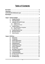
Table of Contents Box Contents ...6 OptionalItems ...6 GA-P35-DS3L/S3L Motherboard Layout 7 Block Diagram ...8 Chapter 1 Hardware Installation 9 1-1 Installation Precautions 9 1-2 Product Specifications 10 1-3 Installing the CPU and CPU Cooler ... Memory 17 1-5 Installing an Expansion Card 18 1-6 Back Panel Connectors 19 1-7 Internal Connectors 21 Chapter 2 BIOS Setup 31 2-1 Startup Screen 32 2-2 The Main Menu 33 2-3 Standard CMOS Features 35 2-4 Advanced BIOS Features 37 2-5 IntegratedPeripherals 39 2-6 Power Management Setup 42 2-7 PnP/PCI Configurations 44 2-8 PC Health Status...
Table of Contents Box Contents ...6 OptionalItems ...6 GA-P35-DS3L/S3L Motherboard Layout 7 Block Diagram ...8 Chapter 1 Hardware Installation 9 1-1 Installation Precautions 9 1-2 Product Specifications 10 1-3 Installing the CPU and CPU Cooler ... Memory 17 1-5 Installing an Expansion Card 18 1-6 Back Panel Connectors 19 1-7 Internal Connectors 21 Chapter 2 BIOS Setup 31 2-1 Startup Screen 32 2-2 The Main Menu 33 2-3 Standard CMOS Features 35 2-4 Advanced BIOS Features 37 2-5 IntegratedPeripherals 39 2-6 Power Management Setup 42 2-7 PnP/PCI Configurations 44 2-8 PC Health Status...

Manual
Page 5
... 54 3-3 Driver CD Information 54 3-4 Hardware Information 55 3-5 Contact Us ...55 Chapter 4 Unique Features 57 4-1 Xpress Recovery2 57 4-2 BIOS Update Utilities 62 4-2-1 Updating the BIOS with the Q-Flash Utility 62 4-2-2 Updating the BIOS with the @BIOS Utility 65 4-3 EasyTune 5 ...67 4-4 Windows Vista ReadyBoost 68 Chapter 5 Appendix ...69 5-1 Configuring Audio Input and Output 69 5-1-1 Configuring...
... 54 3-3 Driver CD Information 54 3-4 Hardware Information 55 3-5 Contact Us ...55 Chapter 4 Unique Features 57 4-1 Xpress Recovery2 57 4-2 BIOS Update Utilities 62 4-2-1 Updating the BIOS with the Q-Flash Utility 62 4-2-2 Updating the BIOS with the @BIOS Utility 65 4-3 EasyTune 5 ...67 4-4 Windows Vista ReadyBoost 68 Chapter 5 Appendix ...69 5-1 Configuring Audio Input and Output 69 5-1-1 Configuring...

Manual
Page 7
GA-P35-DS3L/S3L Motherboard Layout KB_MS COAXIAL OPTICAL ATX_12V LGA775 CPU_FAN ATX COM LPT DDRII1 GA-P35-DS3L/S3L R_USB SYS_FAN2 USB LAN F_AUDIO AUDIO SYS_FAN1 PCIE_3 RTL8111B PCIE_16 PCIE_1 SPDIF_O CODEC PCIE_2 SPDIF_I PCI1 PCI2 IT8718 PCI3 CD_IN Intel® P35 FDD DDRII3 DDRII4 DDRII2 PWR_FAN Intel® ICH9 BATTERY CLR_CMOS SATAII0 SATAII1 JMicron 368 SATAII4 BIOS SATAII5 IDE1 F_USB3 F_USB2 F_USB1 CI F_PANEL PWR_LED "*" Only the GA-P35-DS3L adopts All-Solid Capacitor design. - 7 -
GA-P35-DS3L/S3L Motherboard Layout KB_MS COAXIAL OPTICAL ATX_12V LGA775 CPU_FAN ATX COM LPT DDRII1 GA-P35-DS3L/S3L R_USB SYS_FAN2 USB LAN F_AUDIO AUDIO SYS_FAN1 PCIE_3 RTL8111B PCIE_16 PCIE_1 SPDIF_O CODEC PCIE_2 SPDIF_I PCI1 PCI2 IT8718 PCI3 CD_IN Intel® P35 FDD DDRII3 DDRII4 DDRII2 PWR_FAN Intel® ICH9 BATTERY CLR_CMOS SATAII0 SATAII1 JMicron 368 SATAII4 BIOS SATAII5 IDE1 F_USB3 F_USB2 F_USB1 CI F_PANEL PWR_LED "*" Only the GA-P35-DS3L adopts All-Solid Capacitor design. - 7 -
Manual
Page 8
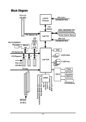
Block Diagram PCIe CLK (100 MHz) LGA775 Processor CPU CLK+/(333/266/200 MHz) PCI Express x16 LAN ATA-133/100/66/33 IDE Channel JMicron 368 x1 PCI Express Bus RJ45 RTL 8111B x1 3 PCI Express x1 x 1 x1 x1 PCIe CLK (100 MHz) PCI Bus Host Interface DDR2 1066/800/667 MHz Intel® P35 Dual Channel Memory MCH CLK (333/266/200 MHz) Intel® ICH9 BIOS 4 SATA 3Gb/s 12 USB Ports CODEC IT8718 Floppy LPT Port COM Port PS/2 KB/Mouse Surround Speaker Out Center/Subwoofer Speaker Out Side Speaker Out MIC Line-Out Line-In SPDIF In SPDIF Out 3 PCI PCI CLK (33 MHz) - 8 -
Block Diagram PCIe CLK (100 MHz) LGA775 Processor CPU CLK+/(333/266/200 MHz) PCI Express x16 LAN ATA-133/100/66/33 IDE Channel JMicron 368 x1 PCI Express Bus RJ45 RTL 8111B x1 3 PCI Express x1 x 1 x1 x1 PCIe CLK (100 MHz) PCI Bus Host Interface DDR2 1066/800/667 MHz Intel® P35 Dual Channel Memory MCH CLK (333/266/200 MHz) Intel® ICH9 BIOS 4 SATA 3Gb/s 12 USB Ports CODEC IT8718 Floppy LPT Port COM Port PS/2 KB/Mouse Surround Speaker Out Center/Subwoofer Speaker Out Side Speaker Out MIC Line-Out Line-In SPDIF In SPDIF Out 3 PCI PCI CLK (33 MHz) - 8 -
Manual
Page 11
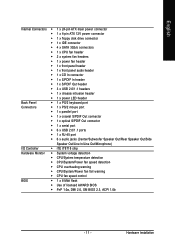
... temperature detection Š CPU/System/Power fan speed detection Š CPU overheating warning Š CPU/System/Power fan fail warning Š CPU fan speed control BIOS Š 1 x 8 Mbit flash Š Use of licensed AWARD BIOS Š PnP 1.0a, DMI 2.0, SM BIOS 2.3, ACPI 1.0b - 11 - Hardware Installation
... temperature detection Š CPU/System/Power fan speed detection Š CPU overheating warning Š CPU/System/Power fan fail warning Š CPU fan speed control BIOS Š 1 x 8 Mbit flash Š Use of licensed AWARD BIOS Š PnP 1.0a, DMI 2.0, SM BIOS 2.3, ACPI 1.0b - 11 - Hardware Installation
Manual
Page 12
... for Q-Flash Š Support for EasyTune (Note 3) Š Support for Xpress Install Š Support for Xpress Recovery2 Š Support for Virtual Dual BIOS Š Norton Internet Security (OEM version) Š Support for Microsoft® Windows® Vista/XP/2000 Š ATX Form Factor; 30.5cm x... hot plug is supported in Windows Vista only) and configure the SATA connectors for AHCI mode. (Refer to Chapter 2, "BIOS Setup," "Integrated Peripherals," for details on enabling AHCI.) (Note 3) Available functions in Easytune may differ by motherboard model. GA-P35-DS3L/S3L Motherboard - 12 -
... for Q-Flash Š Support for EasyTune (Note 3) Š Support for Xpress Install Š Support for Xpress Recovery2 Š Support for Virtual Dual BIOS Š Norton Internet Security (OEM version) Š Support for Microsoft® Windows® Vista/XP/2000 Š ATX Form Factor; 30.5cm x... hot plug is supported in Windows Vista only) and configure the SATA connectors for AHCI mode. (Refer to Chapter 2, "BIOS Setup," "Integrated Peripherals," for details on enabling AHCI.) (Note 3) Available functions in Easytune may differ by motherboard model. GA-P35-DS3L/S3L Motherboard - 12 -
Manual
Page 13
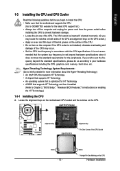
... the power outlet before you begin to install the CPU: • Make sure that the motherboard supports the CPU. (Go to GIGABYTE's website for the latest CPU support list.) • Always turn on the CPU Hardware Installation mended that supports HT Technology and has... the CPU A. The CPU cannot be set beyond the standard specifications, please do so according to Chapter 2, "BIOS Setup," "Advanced BIOS Features," for HT Technology • A BIOS that the system bus frequency be inserted if oriented incorrectly. (Or you wish to set the frequency beyond hardware specifications...
... the power outlet before you begin to install the CPU: • Make sure that the motherboard supports the CPU. (Go to GIGABYTE's website for the latest CPU support list.) • Always turn on the CPU Hardware Installation mended that supports HT Technology and has... the CPU A. The CPU cannot be set beyond the standard specifications, please do so according to Chapter 2, "BIOS Setup," "Advanced BIOS Features," for HT Technology • A BIOS that the system bus frequency be inserted if oriented incorrectly. (Or you wish to set the frequency beyond hardware specifications...
Manual
Page 16
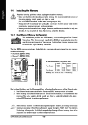
After the memory is installed, the BIOS will appear during the POST. DS/SS - - DS/SS -... is recommended that the motherboard supports the memory. Enabling Dual Channel memory mode will double the original memory bandwidth. GA-P35-DS3L/S3L Motherboard - 16 - DS/SS DS/SS (SS=Single-Sided, DS=Double-Sided, "- -"=No Memory) DDRII1...Flex Memory Technology offers greater flexibility to upgrade by allowing different memory sizes to be used . (Go to GIGABYTE's website for optimum performance. English 1-4 Installing the Memory Read the following guidelines before you are divided into ...
After the memory is installed, the BIOS will appear during the POST. DS/SS - - DS/SS -... is recommended that the motherboard supports the memory. Enabling Dual Channel memory mode will double the original memory bandwidth. GA-P35-DS3L/S3L Motherboard - 16 - DS/SS DS/SS (SS=Single-Sided, DS=Double-Sided, "- -"=No Memory) DDRII1...Flex Memory Technology offers greater flexibility to upgrade by allowing different memory sizes to be used . (Go to GIGABYTE's website for optimum performance. English 1-4 Installing the Memory Read the following guidelines before you are divided into ...
Manual
Page 18
... with a screw. 5. Secure the card's metal bracket to correctly install your card. Make sure the metal contacts on your operating system. GA-P35-DS3L/S3L Motherboard - 18 - Remove the metal slot cover from the power outlet before you begin to prevent hardware damage. Align the card with your... in your computer. Carefully read the manual that supports your expansion card in the expansion slot. 1. If necessary, go to BIOS Setup to make any required BIOS changes for your expansion card. • Always turn off the computer and unplug the power cord from the chassis back panel....
... with a screw. 5. Secure the card's metal bracket to correctly install your card. Make sure the metal contacts on your operating system. GA-P35-DS3L/S3L Motherboard - 18 - Remove the metal slot cover from the power outlet before you begin to prevent hardware damage. Align the card with your... in your computer. Carefully read the manual that supports your expansion card in the expansion slot. 1. If necessary, go to BIOS Setup to make any required BIOS changes for your expansion card. • Always turn off the computer and unplug the power cord from the chassis back panel....
Manual
Page 25
...panel. Message/Power/ Power Speaker Sleep LED Switch Connector MSG+ MSG- The LED keeps blinking when S1 Blinking the system is detected, the BIOS may issue beeps in different patterns to indicate the problem. A front panel module mainly consists of power switch, reset switch, power LED,... hard drive activity LED, speaker and etc. When connecting your system using the power switch (refer to Chapter 2, "BIOS Setup," "Power Management Setup," for information about beep codes. • HD (IDE Hard Drive Activity LED, Blue) Connects to the pin assignments ...
...panel. Message/Power/ Power Speaker Sleep LED Switch Connector MSG+ MSG- The LED keeps blinking when S1 Blinking the system is detected, the BIOS may issue beeps in different patterns to indicate the problem. A front panel module mainly consists of power switch, reset switch, power LED,... hard drive activity LED, speaker and etc. When connecting your system using the power switch (refer to Chapter 2, "BIOS Setup," "Power Management Setup," for information about beep codes. • HD (IDE Hard Drive Activity LED, Blue) Connects to the pin assignments ...

Manual
Page 29
...values and before turning on the two pins to temporarily short the two pins or use a metal object like a screwdriver to Chapter 2, "BIOS Setup," for a few seconds. To clear the CMOS values, place a jumper cap on your computer and unplug the power cord from the...motherboard. • After system restart, go to BIOS Setup to load factory defaults (select Load Optimized Defaults) or manually configure the BIOS settings (refer to touch the two pins for BIOS configurations). - 29 - Hardware Installation date information and BIOS configurations) and reset the CMOS values to factory ...
...values and before turning on the two pins to temporarily short the two pins or use a metal object like a screwdriver to Chapter 2, "BIOS Setup," for a few seconds. To clear the CMOS values, place a jumper cap on your computer and unplug the power cord from the...motherboard. • After system restart, go to BIOS Setup to load factory defaults (select Load Optimized Defaults) or manually configure the BIOS settings (refer to touch the two pins for BIOS configurations). - 29 - Hardware Installation date information and BIOS configurations) and reset the CMOS values to factory ...
Manual
Page 30
...Plug in the power cord and restart your computer. • Always turn off your computer and unplug the power cord. 2. Turn off . GA-P35-DS3L/S3L Motherboard - 30 - You may be handled in accordance with local environmental regulations. Danger of explosion if the battery is turned off your computer ... of the battery holder, making them short for one . English 19) BATTERY The battery provides power to keep the values (such as BIOS configurations, date, and time information) in the CMOS when the computer is replaced with an incorrect model. • Contact the place of...
...Plug in the power cord and restart your computer. • Always turn off your computer and unplug the power cord. 2. Turn off . GA-P35-DS3L/S3L Motherboard - 30 - You may be handled in accordance with local environmental regulations. Danger of explosion if the battery is turned off your computer ... of the battery holder, making them short for one . English 19) BATTERY The battery provides power to keep the values (such as BIOS configurations, date, and time information) in the CMOS when the computer is replaced with an incorrect model. • Contact the place of...
Manual
Page 31
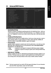
...include conducting the Power-On Self-Test (POST) during system startup, saving system parameters and loading operating system, etc. To see more advanced BIOS Setup menu options, you can press + in Chapter 1 for the beep codes description. • It is recommended that you not alter ... this chapter or introductions of the battery/clearing CMOS jumper in the main menu of the BIOS Setup program. To upgrade the BIOS, use either the GIGABYTE Q-Flash or @BIOS utility. • Q-Flash allows the user to activate certain system features. Inadequately altering the settings may result in...
...include conducting the Power-On Self-Test (POST) during system startup, saving system parameters and loading operating system, etc. To see more advanced BIOS Setup menu options, you can press + in Chapter 1 for the beep codes description. • It is recommended that you not alter ... this chapter or introductions of the battery/clearing CMOS jumper in the main menu of the BIOS Setup program. To upgrade the BIOS, use either the GIGABYTE Q-Flash or @BIOS utility. • Q-Flash allows the user to activate certain system features. Inadequately altering the settings may result in...
Manual
Page 32
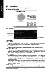
... boots. To show the BIOS POST screen. Note: The setting in BIOS Setup. : Xpress Recovery2 If you to XpressRecovery2 during the POST. Motherboard Model BIOS Version Intel P35 BIOS for P35-DS3L F3a . . . . : BIOS Setup/Q-Flash : XpressRecovery2 : Boot Menu : Qflash 07/12/2007-P35-ICH9-6A79OG0TC-00 Function Keys... on the Full Screen LOGO Show item on BIOS Setup settings. To exit Boot Menu, press . A. After system restart, the device boot order will directly boot from the device configured in Boot Menu. GA-P35-DS3L/S3L Motherboard - 32 - The system will still be...
... boots. To show the BIOS POST screen. Note: The setting in BIOS Setup. : Xpress Recovery2 If you to XpressRecovery2 during the POST. Motherboard Model BIOS Version Intel P35 BIOS for P35-DS3L F3a . . . . : BIOS Setup/Q-Flash : XpressRecovery2 : Boot Menu : Qflash 07/12/2007-P35-ICH9-6A79OG0TC-00 Function Keys... on the Full Screen LOGO Show item on BIOS Setup settings. To exit Boot Menu, press . A. After system restart, the device boot order will directly boot from the device configured in Boot Menu. GA-P35-DS3L/S3L Motherboard - 32 - The system will still be...
Manual
Page 33
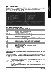
Use arrow keys to move among the items and press to accept or enter a sub-menu. (Sample BIOS Version: GA-P35-DS3L F3a) CMOS Setup Utility-Copyright (C) 1984-2007 Award Software ` Standard CMOS Features ` Advanced BIOS Features ` Integrated Peripherals ` Power Management Setup ` PnP/PCI Configurations ` PC Health Status ` MB Intelligent ...in the Item Help block on the right side of the submenu. • If you do not find the settings you enter the BIOS Setup program, the Main Menu (as usual, select the Load Optimized Defaults item to set your system to exit the help screen (General...
Use arrow keys to move among the items and press to accept or enter a sub-menu. (Sample BIOS Version: GA-P35-DS3L F3a) CMOS Setup Utility-Copyright (C) 1984-2007 Award Software ` Standard CMOS Features ` Advanced BIOS Features ` Integrated Peripherals ` Power Management Setup ` PnP/PCI Configurations ` PC Health Status ` MB Intelligent ...in the Item Help block on the right side of the submenu. • If you do not find the settings you enter the BIOS Setup program, the Main Menu (as usual, select the Load Optimized Defaults item to set your system to exit the help screen (General...
Manual
Page 34
...to restrict access to the system and BIOS Setup. It allows you to save the current BIOS settings to make changes. „ Save & Exit Setup Save all changes and the previous settings remain in effect. You can also carry out this task.) GA-P35-DS3L/S3L Motherboard - 34 - First enter the ...profile name (to erase the default profile name, use this menu to configure the clock, frequency and voltages of your system becomes unstable and you have loaded the BIOS default settings, you to a profile. A...
...to restrict access to the system and BIOS Setup. It allows you to save the current BIOS settings to make changes. „ Save & Exit Setup Save all changes and the previous settings remain in effect. You can also carry out this task.) GA-P35-DS3L/S3L Motherboard - 34 - First enter the ...profile name (to erase the default profile name, use this menu to configure the clock, frequency and voltages of your system becomes unstable and you have loaded the BIOS default settings, you to a profile. A...
Manual
Page 35
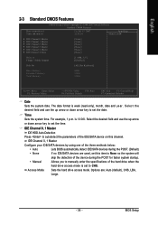
...drive access mode is set this channel. Options are used, set to manually enter the specifications of the three methods below: • Auto Lets BIOS automatically detect IDE/SATA devices during the POST for faster system startup. • Manual Allows you to CHS. The date format is 13:0:0. For... example, 1 p.m. Select the desired field and use the up arrow or down arrow key to set the date. BIOS Setup Select the desired field and use the up arrow or down arrow key to set the time. English 2-3 Standard CMOS Features Date (mm:dd...
...drive access mode is set this channel. Options are used, set to manually enter the specifications of the three methods below: • Auto Lets BIOS automatically detect IDE/SATA devices during the POST for faster system startup. • Manual Allows you to CHS. The date format is 13:0:0. For... example, 1 p.m. Select the desired field and use the up arrow or down arrow key to set the date. BIOS Setup Select the desired field and use the up arrow or down arrow key to set the time. English 2-3 Standard CMOS Features Date (mm:dd...
Manual
Page 36
...Head Number of the currently installed hard drive. Drive A Allows you to selects the type of the two methods below: • Auto Lets BIOS automatically detect IDE/SATA devices during the POST. (Default) • None If no IDE/SATA devices are used, set this channel. All ...disk drive error but it will stop for faster system startup. Base Memory Also called conventional memory. GA-P35-DS3L/S3L Motherboard - 36 - Extended IDE Drive Configure your IDE/SATA devices by the BIOS POST. Cylinder Number of the IDE/SATA device on Allows you do not install a floppy disk drive...
...Head Number of the currently installed hard drive. Drive A Allows you to selects the type of the two methods below: • Auto Lets BIOS automatically detect IDE/SATA devices during the POST. (Default) • None If no IDE/SATA devices are used, set this channel. All ...disk drive error but it will stop for faster system startup. Base Memory Also called conventional memory. GA-P35-DS3L/S3L Motherboard - 36 - Extended IDE Drive Configure your IDE/SATA devices by the BIOS POST. Cylinder Number of the IDE/SATA device on Allows you do not install a floppy disk drive...
Manual
Page 37
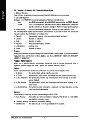
...the minus key (or ) to exit this feature. Password Check Specifies whether a password is required for booting the system and for entering the BIOS Setup program. (Default) A password is required every time the system boots, or only when you install a CPU that supports this menu ...Limit CPUID Max. Press to move it up or down on the list. Setup System A password is only required for entering the BIOS Setup program. Capability Enables or disables the S.M.A.R.T. (Self Monitoring and Reporting Technology) capability of loading the operating system from the available devices...
...the minus key (or ) to exit this feature. Password Check Specifies whether a password is required for booting the system and for entering the BIOS Setup program. (Default) A password is required every time the system boots, or only when you install a CPU that supports this menu ...Limit CPUID Max. Press to move it up or down on the list. Setup System A password is only required for entering the BIOS Setup program. Capability Enables or disables the S.M.A.R.T. (Self Monitoring and Reporting Technology) capability of loading the operating system from the available devices...


